Table of Contents
Advertisement
Quick Links
Advertisement
Table of Contents

Related Manuals for Esco Medical MIRI TL 6


Summary of Contents for Esco Medical MIRI TL 6
- Page 1 CE 1023 ® Multi room incubator MIRI TL 6 Rev. 1.7 Rx only...
- Page 2 For Technical Service, contact North America Esco Technologies, Inc. 2940 Turnpike Drive, Units 15-16 • Hatboro, PA 19040, USA Toll-Free USA and Canada 1-877-479-3726 Tel 215-441-9661 • Fax 215-441-9660 us.escoglobal.com • usa@escoglobal.com Rest of World Esco Micro Pte. Ltd. 21 Changi South Street 1 • Singapore 486 777 Tel +65 6542 0833 •...
- Page 3 (2) years from the date of original purchase, provided the instrument is calibrated and maintained in accordance with this manual. During the warranty period Esco Medical will, at our option, either repair or replace a MIRI TL 6 User Manual Rev.
- Page 4 This warranty is limited to repairing the instrument per Esco Medical's specifications. When you return an instrument to Esco Medical for service, repair or calibration, we rec- ommend shipment using the original shipping foam and container. If the original packing materials are not available, we recommend the following guide for repackaging: •...
- Page 5 In an event where the seal must be broken to gain internal access to the instrument, you must first contact Esco Medical Ltd. You will be required to provide us with the serial number for your instrument, as well as a valid reason for breaking the Quality Seal.
-
Page 6: Table Of Contents
Table of contents 1 How to use this manual ..........................9 2 Safety Warning ............................9 3 Indication for use............................9 4 About the product ............................ 10 5 Accessories supplied ..........................11 6 Manuals supplied............................11 6.1 The user manual ..........................11 6.2 The validation manual ........................ - Page 7 14.1 Temperature alarms ........................27 14.2 Gas level alarms ..........................29 14.3 Gas pressure alarms ........................30 14.4 UVC light alarm ..........................31 14.5 Multiple alarms ..........................31 14.6 Loss of power alarm ........................32 15 Changing the set points ........................32 15.1 Temperature set point ........................
- Page 8 24 Temperature validation ........................78 25 Gas level validation ..........................78 26 Alarm switches for an external system ..................79 27 Writing area on the compartment lids..................80 28 Maintenance ............................81 29 Emergency Procedures........................81 30 User Troubleshooting .......................... 83 31 Specifications............................
-
Page 9: How To Use This Manual
1 How to use this manual The manual is designed to be read by sections, and not ideally cover to cover. This means that if the manual is read, from start to finish, there will be some repetition and overlap. We recommend the following method to go through the manual: first, familiarize yourself with the safety instructions;... -
Page 10: About The Product
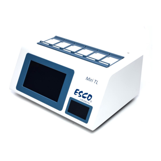
4 About the product The Esco Medical MIRI TL 6 is a multi-room CO incubator with time-lapse capability, ® making it possible to incubate up to 84 embryos and generate time-lapse microscopy images of the development stages during the incubation. -
Page 11: Accessories Supplied
5 Accessories supplied • 1 VOC/HEPA filter capsule • 2 HEPA filters for input gas supply • 1 USB stick containing Esco Medical Data logger software and PDF versions of the manuals • 1 data cable 6 Manuals supplied The MIRI TL 6 incubator comes with 3 manuals as standard: ®... -
Page 12: The Validation Manual
6.2 The validation manual Is intended for trained technical personnel performing the installation, detailing the proce- dures and specifications needed to ensure that the device is safe and can be taken into clin- ical use. The manual can also be used as a guide for validation tests that should be performed regularly. - Page 13 - Warning on the back of the incubator indicates that an earth connection is needed, mains infor- mation, and “ON/OFF” push-push button - ‘Lightning bolt’ indicates the potential risk of electrical shock (never remove any cover) - Model - Mains power rating - CE mark - Not protected against ingress of water - Manufacturers address and country of origin...
-
Page 14: Important Safety Instructions And Warnings
Figure 7.3 Compartments numbers layout 8 Important Safety Instructions and warnings 8.1 Before installation 1. Do not use the product if the package is damaged. Contact Esco Medical or the local rep- resentative 2. Read the user manual completely before use 3. -
Page 15: Post Installation
0.6 bar (8.70 PSI) 13. Never use a non-Esco Medical filter; it will void the warranty 14. Do not use the product without a proper Esco Medical VOC/HEPA filter attached 9 Getting started... -
Page 16: Mains Connections
10 Mains connections The MIRI TL 6 incubator comes with a detachable mains power cord. The power cord is ® prepared for the country in which the unit is intended to be used in. Do not defeat the safety purpose of the grounding-type plug! A grounding type plug has two blades, and a third prong. -
Page 17: Hepa / Voc Filter
For both gases, always use a high-quality pressure regulator that can be set with the necessary precision. Figure 11.2 Pressure regulator Connect the CO gas to the CO inlet with a suitable silicone tube. Make sure that the tube is secured with a clip, so that it does not accidentally loosen during sudden pressure fluctuation. -
Page 18: Installation Of A New Filter Capsule
VOC levels in the 0.5 ppm range will typically allow for acceptable blastocyst development and reasonable pregnancy rates but will result in a high percentage of miscarriages. A combined HEPA and VOC filter (carbon filter) is integrated in the construction of the MIRI ®... -
Page 19: Removing The Old Filter
A filter element that has been fitted incorrectly will cause the unit not to work as intended. This is dangerous. 12.2 Removing the old filter The filter is removed by gently pulling it straight out using both hands together. Never run the MIRI TL 6 with the filter element missing! Dangerous particle ®... -
Page 20: Activating The Heat And Gas Control
13.1 Activating the heat and gas control The heat and gas control are activated using the power On/Off switch at the rear. ® Figure 13.1.1 MIRI TL 6 rear ‘Please wait’ message appears on the screen while system is booting up for work. Figure 13.1.2 Loading view Soon after system activation the main display will show the following 3 parameters Temperature = Temperature in... -
Page 21: Menu System
Figure 13.1.3 Main display 13.2 Menu system Press menu in main display and navigate using the buttons on the touchscreen. Main menu consists of 5 sub-menu applications: Calibration, CO Setup, O Setup, Temperature Setup, and UVC Light. Figure 13.2.1 Menu display From main display the user can directly access to second main display pressing on the arrow pointing right. -
Page 22: Calibration
Figure 13.2.2 Main display 2 13.2.1 Calibration From menu display choose the calibration application. Calibration can be performed for Temperature, CO and O Figure 13.2.1 Calibration sub-menu Changing the calibration value should only be done based specific measurements taken and evaluated by a trained user or technician. MIRI TL 6 User Manual Rev. -
Page 23: Temperature Calibration
13.2.1.1 Temperature calibration Temperature calibration consist of 12 calibration zones. Figure 13.2.1.1.1 The 12 calibration zones Each compartment has two internal temperature sensors. One is in the compartment lid and other one is in the compartment bottom. For temperature calibration use the up or down arrow keys. Figure 13.2.1.1.2 The T1 zone value setting MIRI TL 6 User Manual Rev. -
Page 24: Co Calibration
13.2.1.2 CO calibration Calibrate the gas levels by pressing the up or down arrow keys. Figure 13.2.1.2.1 CO and O calibration Calibration is done by adjusting the CO level according to measurements done on the gas sampling outlet using a precision CO measurement device only. -
Page 25: O 2 Setup
The CO flow rate is shown when the setpoint is defined. The flow rate cannot be adjusted; this is the amount of CO gas put into the system while regulating. The volume is shown in liters per hour. Normally it will fluctuate with the CO regulation. -
Page 26: Uvc Light
Figure 13.2.4.1 Multi temperature setup It is recommended to keep the setting for a single (common) set point if all com- partments run at the same temperature. In that way it will be easier to make adjust- ments to the set point as the adjustment will only have to be done once instead of six times (i.e. -
Page 27: Alarms
14 Alarms In case of a fault-condition, the affected parameter value will appear in red, along with an audible alarm. The audible alarm can be muted (toggled on/off for a period of 5-minutes) by pressing the alarm on/off button once. The alarm on/off button will pulse red: Figure 14.1 Alarm key which indicate the alarm condition The alarm pattern is 3 short beeps followed by a 3-second pause. - Page 28 Figure 14.1.2 Temperature is too low in compartment 1 Temperature is too low in compartment 1. The display will force-lock on the alarm condi- tion, along with an audible alarm signal. If the alarm is muted by pressing the alarm on/off button, the button will pulse red.
-
Page 29: Gas Level Alarms
14.2 Gas level alarms or O level alarms are activated if the concentration of the gas deviates more than ±1% from the set value. Remember that changing the set point more than ±1% from the current gas level will result in an in a CO or O level alarm. -
Page 30: Gas Pressure Alarms
concentration is too high. The display will force-lock on the alarm condition, along with an audible alarm signal. If the alarm is muted by pressing the alarm on/off button, the button will pulse red. 14.3 Gas pressure alarms If the CO or N gas supply is not attached correctly or the wrong gas pressure is applied to the system, the device will go into the gas pressure alarm mode. -
Page 31: Uvc Light Alarm
pressure is incorrect. The display will force-lock on the alarm condition, along with an audible alarm signal. If the alarm is muted by pressing the alarm on/off button, the button will pulse red. 14.4 UVC light alarm If the UVC light malfunctions, the following alarm message appears in the main display: Figure 14.4.1 UVC light alarm User should consult the distributor for further guidance or service inspection. -
Page 32: Loss Of Power Alarm
Figure 14.5.1 Multiple alarms In compartment 1 the temperature is too high, the CO is not connected or the CO pres- sure is incorrect, and there is also a UVC light malfunction. 14.6 Loss of power alarm If the power is disconnected, the incubator will give an audible alarm for approximately 4 seconds and the LED in the alarm on/off button will flash. - Page 33 Multi Temperature Setpoint setting Changing the multi temperature settings, follow these instructions: 1) In main display press Menu; Figure 15.1.1 Main display 2) Menu window will appear. Press Temperature Setup icon; Figure 15.1.2 Menu window 3) Choose settings according desired working conditions. Multi Temp SP –...
- Page 34 Figure 15.1.3 Multi temperature setpoint press Exit; the setup will be saved automatically. Once the option is selected, Temperature value setting To change the set point for temperature, follow these instructions: 1) In main display press Setpoint; Figure 15.1.1 Main display 2) New Setpoint page will appear.
- Page 35 Figure 15.1.4 Setpoint page display 3) In new window you can choose the compartment for which you want to set the Setpoint. The table below shows which Setpoint refers to which compartment: Setpoint number Compartment number Temperature Setpoint 1 Compartment number 1 Temperature Setpoint 2 Compartment number 2 Temperature Setpoint 3...
-
Page 36: Co Setpoint
4) Use arrows to set value: the arrow pointing down decreases the value, the arrow pointing up increases the value. The value changes by 0.1 C steps. Figure 15.1.6 Temperature Setpoint 1 display When the desired value is set, press the Exit icon; the value will be saved automatically. Repeat steps for other compartments if Multi Temperature setting is chosen (Multi Temp SP –... - Page 37 Figure 15.2.1 Main display 2) Menu window will appear. Press CO2 Setup icon; Figure 15.2.2 Menu window 3) Choose settings according to the desired working conditions. CO2 Regulation – On – CO gas activated. CO2 Regulation – Off – CO gas deactivated.
- Page 38 Figure 15.2.3 CO Set up display When desired working condition has been selected, press Exit; the setting will be saved au- tomatically. 4) Use the Exit button to navigate to the main display and then press Setpoint. Figure 15.2.4 Main display MIRI TL 6 User Manual Rev.
- Page 39 5) On the Setpoint page press Gas Setpoint icon. Figure 15.2.5 Setpoint page display 6) Use the arrows to set value. The arrow pointing down decreases the value, the arrow pointing up increases the value. The value changes in 0.1 % steps. Figure 15.2.6 Gas setpoint display When the desired value is set, press the Exit icon;...
-
Page 40: Setpoint
15.3 O Setpoint concentration can be adjusted in the range from 4.9% to 20%. The default O set point is 5%. To change the set point for the O concentration, follow these instructions: 1) On the main display press Menu: Figure 15.3.1 Main display 2) Menu window will appear. - Page 41 3) Choose settings according to the desired working conditions. O2 Regulation – On – O gas activated; O2 Regulation – Off – O gas deactivated. Figure 15.3.3 O Set up display When the desired working conditions are selected, press Exit; the setting will be saved au- tomatically.
- Page 42 5) On the Setpoint page press Gas Setpoint icon. Figure 15.3.5 Setpoint page display 6) Use arrows to set value. The arrow pointing down decreases the value, the arrow pointing up increases the value. The value changes in 0.1% steps. Figure 13.3.6 Gas setpoint display When the desired value is set, press Exit icon;...
-
Page 43: Surface Temperatures And Calibration
16 Surface temperatures and calibration In this section, the temperature controls of the MIRI TL 6 are described in more detail. ® There are 12 completely independent PID controllers for temperature on the MIRI TL 6. ® Each controller is responsible for controlling the temperature of a separate area. Each of the 12 available areas is equipped with its own separate temperature sensor and heater, allowing the user to adjust the temperature within each area separately and with high precision. -
Page 44: Temperature Calibration Example
16.1 Temperature calibration example This section shows how to calibrate Compartment 1 temperature as an example. The “T1” in the menu is used to calibrate the temperature of the bottom of compartment 1. Navigation to temperature calibration submenu: 1) On the main display press Menu: Figure 16.1.1 Main display 2) In main menu window press Calibration icon: Figure 16.1.2 Main menu... - Page 45 3) In calibration menu press Temperature: Figure 16.1.3 Calibration menu 4) Press Temperaturezone 1. Figure 16.1.4 12 temperature zones MIRI TL 6 User Manual Rev. 1.7 ®...
-
Page 46: Gas Pressure And Calibration
Set value with arrows (pointing up – increase value, pointing down – decrease value) ac- cording to the external thermometer reading. Figure 16.1.5 Temperature T1 calibration ‘T1’ is used to adjust the bottom temperature of compartment 1. “T7”is used to adjust the lid temperature of the same compartment. -
Page 47: Gas Calibration Example
The internal pressure sensor cannot be calibrated by the user. Under normal circumstances it will remain without drift for the lifetime of the device. 17.1 Gas calibration example This section shows how to calibrate CO gas as an example. Navigation to gas calibration submenu: 1) On the display press menu: Figure 17.1.1 Main display 2) In main menu window press Calibration icon. -
Page 48: Firmware
3) Adjust CO level according to measurement done on the gas sampling outlet using a precision gas measurement device. For adjusting use arrows (pointing up – increase value, pointing down – decrease value). Figure 17.1.3 CO and O calibration Changing the calibration value should only be done based on specific measurements by a trained user or a technician. - Page 49 If measurements are done in liquids that are not being incubated in the compartments of the MIRI TL 6, the liquids must be maintained at 37.0 C (or the set- ® point of the incubator), or the temperature level must be set to the correct level in the calibration dialogue window onscreen (corresponding to the measurement done with an external device): Otherwise, the measurement will be incorrect, as pH is a temperature dependant measurement.
-
Page 50: Screen Functions
Figure 19.2 pH calibration screen Using the plus and minus buttons, set the buffer levels to correspond to the buffers used. Before measuring in the culture media, calibrate the probe in the 2 or 3 buffers. Rinse the probe between each insertion. After the calibration has been performed and saved, a quick measurement can be done in the culture media contained in the pH measuring spot of the CultureCoin ®... - Page 51 Figure 20.1 No active time-lapse Figure 20.2 One active time-lapse When a time-lapse is running normally there will be a green status indication in the main view. If the MIRI TL 6 finds the wells in the correct position, the system will show a yellow status ®...
- Page 52 Figure 20.3 Time-lapse calibrating If the time-lapse is paused the system will indicate “Suspended”. A time-lapse may be suspended if for instance the dish is removed for a culture media change, manual observation or manipulation of the embryo. Figure 20.4 Suspended time-lapse MIRI TL 6 User Manual Rev.
-
Page 53: Start A Time-Lapse
20.1 Start a time-lapse Pressing the circle for an empty compartment on the main view starts a time-lapse dialogue: First select a patient from the list. Patients can only be created or edited on the MIRI TL 6 Viewer. The patient data ®... - Page 54 Figure 20.1.2 Test Patient selection If no patient has been sent from the TL Viewer the screen below will be shown. Figure 20.1.3 No patient sent from TL Viewer view MIRI TL 6 User Manual Rev. 1.7 ®...
- Page 55 Or if the required network connection has been interrupted: Figure 20.1.4 Network connection interruption view When the correct patient has been selected, the active positions in the CultureCoin must ® be selected (i.e. the wells containing an embryo). Position 1 – 14 represent the 14 wells on the CultureCoin ®...
-
Page 56: The Calibration Processes
Figure 20.1.5. View of positions 1-9 selected as active Press the Start timelapse button. Now the time-lapse calibration will start. 20.2 The calibration processes Figure 20.2.1 Test patient calibration pending First the screen will show the compartment view with the message “Calibration Pending”. If the CultureCoin is placed correctly in the compartment and the embryos are placed in ®... - Page 57 During the calibration process the middle area will turn yellow to indicate that the process is active. Figure 20.2.2 Active automatic calibration process indication If the calibration process is successful, the images will appear in the active positions. If one or several positions fails, the system will indicate this with a red warning showing that the automatic process was unsuccessful.
-
Page 58: The Compartment View
20.3 The compartment view The compartment view shows the detailed information for the selected compartment. If the compartment has an active time-lapse, the compartment view will show the activity. The 14 circles in a ‘revolver’ pattern show the 14 wells of the CultureCoin . - Page 59 Figure 20.3.2 Sleeping mode view To the left of the big circle is the vertical slider for the focal planes. By taping on it, it is pos- sible to move up and down the focal planes. The blue dot shows the current level displayed. All the images will shift focal planes at the same time.
- Page 60 Figure 20.3.3 Maximized time-lapse position view You can scroll through the 6 compartments using the left and right arrows. The circled arrow pointing left on the top left-hand corner of the screen will take you back to the main view. If no time-lapse is running the screen will indicate that the compartment is empty.
-
Page 61: Settings
20.4 Settings Pressing the Settings button in the main view (cog wheels icon) will open a window where the number of focal planes and the time interval between each image can be set (cycle time). By default the cycle times can be set at 5, 10 or 20 minutes. The focal planes can be set at 3, 5 or 7. -
Page 62: Adjustments Live View
Figure 20.4.2 Notification view: Changes disabled while timelapses are running 20.5 Adjustments live View The live view can be used for manual adjustment and calibration if the automatic process has failed. First, try to adjust the CultureCoin position and rerun the automatic calibration. ®... - Page 63 Figure 20.5.1 Confirmation dialogue Figure 20.5.2 Time-lapses suspended view A compartment must be selected from the list on the top of the screen. A black background indicates that there is no active time-lapse running in the compartment. A green background indicates that time-lapse is running normally. A red background indicates that there are calibration failures for some of the position.
- Page 64 When a compartment with an active time-lapse is selected, 14-dish positions will be shown at the bottom of the screen. A white position background indicates that is has not yet been calibrated. A black background indicates that the position is not active (not selected at the start of time- lapse).
- Page 65 It is important to understand that only the area inside the square will be shown in the time- lapse movie. By selecting the square tool, the square size can be adjusted. This is necessary to compensate for differences in well sizes. and size according to focal plane. The square position can be moved by single taps on the live view screen.
- Page 66 Active position can be deactivated by pressing the “CLEAR” button. When a position is activated it will appear in compartment (time-lapse view). When it is deactivated it will disappear from compartment (time-lapse view). Any images taken previously will remain but new images will not be acquired. Exposure control can be set according to variations in the light conditions.
-
Page 67: Warnings
Figure 20.5.6 All wells adjusted correctly Manual override of the automatic features of the system should only be done if the system fails to find the correct calibration repeatedly. Since the user manually con- trols the motors in the live view, it is possible to move the motors out of bounds and trigger the mechanical limit switches. - Page 68 Figure 20.6.1 Lid opening warning Clear the alarm by pressing the area and entering the compartment view. Then either end or suspend the time-lapse and recalibrate, or just confirm that the patient is still there Figure 20.6.2 Compartment view after opened lid The system will continue to generate time-lapse images after lid opening.
- Page 69 Figure 20.6.3 Temperature warning screen Remove the dish immediately if the temperature conditions are dangerous for the embryos. The compartments are completely independent, so the dish can safely be moved to another position if that compartment shows a stable temperature. Remember to end the time-lapse and start a new one at the changed position.
- Page 70 While the server is disconnected it is not possible to start new time-lapses as the patients cannot be allocated to the unit. All the incubation functions have level alarms that will be shown in the image by the relevant button turning red. The alarm display is of the non-latching type – so any alarm condition that goes away by itself is not directly visible to the user.
-
Page 71: The Data-Logging Temperature View
alarms are shown in the same way – just under O for level and N for pressure. Figure 20.6.7 HDD full memory alert HDD full (transfer data to an external drive or connect to the server). 20.7 The data-logging temperature view Pressing the temperature icon will change the view to a chart view of the temperature. -
Page 72: The Data-Logging Co
On the history view it is possible to see the graphs for the temperature data. It is possible to toggle the graphs on/off for individual compartments, by pressing the corresponding cir- cled number. With the period buttons, hour, day, week, it is possible to change the period viewed. By dragging a finger over the area that one wishes to enlarge, it is possible to zoom in. -
Page 73: The Data-Logging Alarm View
Figure 20.9.1 O data graph 20.10 The data-logging alarm view Pressing the alarm bell opens the alarm view. The alarm view depicts all the parameters and any alarm states in an overview graphical format. Each alarm is represented by a red block that increases in size the longer the alarm lasts. -
Page 74: Culturecoin
21 CultureCoin® The only dish that can be used with the MIRI TL 6 is the proprietary CultureCoin . The ® ® bottom of the MIRI TL 6 compartments are shaped to fit the contour of the dish. It can only ®... - Page 75 Place the embryo on the small circular area. Each culture well can hold around 25 µl of cul- ture media. Finding correct well automatically is sensitive to errors when the embryo is positioned on the side of the well where it rests against the side. Position embryos carefully so they are in the centre of the circle of the well to avoid this problem.
-
Page 76: Miri ® Tl 6 Viewer
A larger reservoir outside the culturing area can be used for pH validation. The reservoir can be closed with a gas permeable silicone plug that will stop evaporation (without using any oil layer that may cause a problem for most pH probes). Fill the reservoir and measure pH using a combination of a probe and the pH measuring system built into the MIRI TL 6. -
Page 77: The Manufacturer Recommended Disinfection Procedure
Periodic cleaning of the device (with no embryos in): Wearing gloves and good handling techniques are important to successful cleaning. 1. It is recommended that the unit is cleaned with aqueous 70% isopropyl alcohol. Moisten a sterile wipe (Gamma Wipe 300) and clean all internal and external surfaces of the device by rubbing the wipe against the surfaces 2. -
Page 78: Temperature Validation
Any logging system that uses standard PT-1000 sensors may be used. Esco Medical can supply an external logging system for the sensors. 25 Gas level validation The gas concentration in each compartment of the MIRI TL 6 incubator can be validated by ®... -
Page 79: Alarm Switches For An External System
Figure 25.1 External compartments gas level validation ports Each sample port is directly connected to the correspondingly numbered compartment. The gas sample will be taken ONLY from the specific compartment. An external automatic gas sampler, can be connected to the ports for continual validation. -
Page 80: Writing Area On The Compartment Lids
ote that if a current source is attached to the 3.5mm jack connector the maximum current rating is between 0 – 1.0 Amp. If a voltage source is attached then the limitation is between 0 – 50V AC or DC. If there is no alarm, the switch within the unit will be in ‘ON’... -
Page 81: Maintenance
28 Maintenance The MIRI TL 6 incubator is designed to be easy to use. However, reliable and safe operation ® of this equipment is based on the following conditions: 1. Correct calibration of temperature and gas using high precision equipment in the intervals prescribed by clinical practice at the laboratory where the MIRI TL 6 is in use. - Page 82 In case of a single temperature alarm on the unit. Remove the samples from the affected compartment. These can be relocated to any of the 5 other compartments where there is room. Each compartment is independent so the remain- ing 5 compartments will function normally. In case of multiple temperature alarms on the unit.
-
Page 83: User Troubleshooting
30 User Troubleshooting Table 30.1 Heating system Symptom Cause Action The unit is switched off at Switch on at the back, or con- No heating, display is off the back or not connected to nect power the power The set point for tempera- Check the desired temperature No heating ture is wrong... - Page 84 PC not properly at- cable supplied with unit tached Table 30.5 Display Symptom Cause Action Replace the PCB: Contact your Missing segment(s) in display Failure in the PCB Esco Medical Distributor for de- tails MIRI TL 6 User Manual Rev. 1.7 ®...
-
Page 85: Specifications
31 Specifications Table 31.1 Specifications Technical specifications MIRI ® TL 6 Overall dimensions (WxDxH) 950 x 585 x 375 mm Weight 60 kg Mild steel / Aluminum / POM / Stain- Material less steel Power supply 115V 60Hz OR 230V 50Hz Power consumption 330 W Temperature range... -
Page 86: Electromagnetic Compatibility
32 Electromagnetic Compatibility Guidance and manufacturer’s declaration – electromagnetic emissions The MIRI ® TL 6 is intended for use in the electromagnetic environment specified below; the cus- tomer or the user of MIRI ® TL 6 should ensure that it is used in such an environment: Emissions test Compliance Electromagnetic environment –... - Page 87 Guidance and manufacturer’s declaration – electromagnetic immunity ® The MIRI TL 6 is intended for use in the electromagnetic environment specified below; the cus- ® tomer or the user of MIRI TL 6 should ensure that it is used in such an environment: IEC 60601 Compli- Electromagnetic environment-...
- Page 88 Recommended separation distances between portable and mobile RF communication equipment and the MIRI TL 6 ® The MIRI TL 6 is intended for use in an electromagnetic environment in which radiated RF dis- ® turbances are controlled. The customer or the user of the MIRI TL 6 can help prevent electro- ®...
Need help?
Do you have a question about the MIRI TL 6 and is the answer not in the manual?
Questions and answers