Table of Contents
Advertisement
Advertisement
Table of Contents

Related Manuals for MSI 945G Neo


Summary of Contents for MSI 945G Neo
- Page 1 945G Series MS-7176 (v1.X ATX Mainboard) G52-M7176X8...
-
Page 2: Fcc-B Radio Frequency Interference Statement
Manual Rev: 1.1 Release Date: JUNE 2005 FCC-B Radio Frequency Interference Statement This equipment has been tested and found to comply with the limits for a class B digital device, pursuant to part 15 of the FCC rules. These limits are designed to provide reasonable protection against harmful interference when the equipment is operated in a commercial environment. -
Page 3: Copyright Notice
Alternatively, please try the following help resources for further guidance. † Visit the MSI homepage & FAQ site for technical guide, BIOS updates, driver updates, and other information: http://www.msi.com.tw & http://www.msi. -
Page 4: Safety Instructions
Safety Instructions Always read the safety instructions carefully. Keep this User’s Manual for future reference. Keep this equipment away from humidity. Lay this equipment on a reliable flat surface before setting it up. The openings on the enclosure are for air convection hence protects the equip- ment from overheating. -
Page 5: Weee Statement
WEEE Statement... -
Page 8: Table Of Contents
CONTENTS FCC-B Radio Frequency Interference Statement ............ii Copyright Notice ......................iii Technical Support ......................iii Revision History ......................iii Safety Instructions ......................iv WEEE Statement ......................v Chapter 1. Getting Started ..................1-1 Mainboard Specifications ................... 1-2 Mainboard Layout ....................1-4 Packing Contents .................... - Page 9 Front USB Connectors: JUSB1 / JUSB2 ..............2-18 Front Panel Audio Connector: JAUD1 ............2-18 IEEE 1394 Connector: J1394_1/J1394_2 (Optional) ..........2-19 D-Bracket™ 2 Connector: JDB1 .............. 2-20 FWH/LPC Debugging Pin Header: JLPC1 ..........2-22 Jumpers ......................2-23 Chassis Intrusion Switch Connector: JCI1 ..........2-23 Clear CMOS Jumper: JBAT1 ..............
- Page 10 Core Center (for Pentium 4 CPU) ..............4-14 Left-wing: Current system status ............4-15 Right-wing: PC hardware status during real time operation ....4-15 Audio Speaker Setting ..................4-16 Power on Agent ....................4-18 Power On ....................4-18 Power Off / Restart ................... 4-19 Auto Login ....................
-
Page 11: Chapter 1. Getting Started
Getting Started Chap t er 1 . Ge tting Started Getting Started Thank you for choosing the 945G Series (MS-7176) v1.x ATX mainboard. The 945G Series mainboard is based on Intel ® 945G and Intel ICH7/ICH7R chipset for optimal system efficiency. ®... -
Page 12: Mainboard Specifications
Supports 3/4 pin CPU Fan Pin-Header with Fan Speed Control. † Supports up to Pentium 4 3XX, 5XX, 6XX & P4EE (Intel Pentium 4 Processor † with HT Technology Extreme Edition). (For the latest information about CPU, please visit http://www.msi.com.tw/program/ products/mainboard/mbd/pro_mbd_cpu_support.php) Chipset Intel 945G chipset †... - Page 13 Getting Started - Can connect up to Six Ultra ATA drives. SATAII controller integrated in ICH7/ICH7R. † - Up to 300MB/sec transfer speed. - Can connect up to four SATAII devices. - Serial ATA RAID 0, RAID 1, RAID 10, RAID 5 and Matrix RAID. (for ICH7R) VIA 6410, chipest.
-
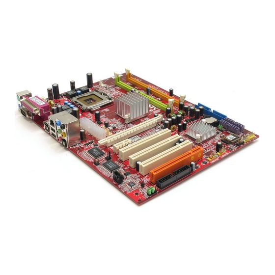
Page 14: Mainboard Layout
M S-7176 ATX Mainboard Mainboard Layout JLPC1 JPW1 Top : mouse CPUFAN1 JCI1 Winbond Bottom: keyboard W83627THG Top : Parallel Por t Bottom: COM port VGA port ports Top: LAN Jack Intel Botto m: USB ports 945G PWRFAN1 Line-In Line-Out T:RS-Out M:CS-Out B:SPD IF Out... -
Page 15: Packing Contents
Getting Started Packing Contents MSI Driver/Utility CD SATA Cable *2 MSI motherboard D-Bracket 2 Standard Cable for Power Cable (Optional) IDE Devices Standard Cable for User’s Guide Back IO Shield Floppy Disk * The pictures are for reference only and may vary... -
Page 16: Chapter 2. Hardware Setup
Hardware Setup Chapter 2. Hardware Setup Hardware Setup This chapter tells you how to install the CPU, memory modules, and expansion cards, as well as how to setup the jumpers on the mainboard. Also, it provides the instructions on connecting the periph- eral devices, such as the mouse, keyboard, etc. -
Page 17: Quick Components Guide
M S-7176 ATX M ainboard Quick Components Guide... -
Page 18: Central Processing Unit: Cpu
If you do not have the CPU cooler, contact your dealer to purchase and install them before turning on the computer. For the latest information about CPU, please visit http://www.msi.com.tw/ program/products/mainboard/mbd/pro_mbd_cpu_support.php. MSI Reminds You... -
Page 19: Cpu & Cooler Installation
CPU Clip to clip the CPU up, pressing the clips on both sides to the center, as the arrows shown. MSI Reminds You... 1. Confirm if your CPU cooler is firmly installed before turning on your system. - Page 20 Hardware Setup 5. The CPU has a plastic cap on it to 6. Remove the cap from lever hinge side protect the contact from damage. (as the arrow shows). The pins of Before you have installed the CPU, socket reveal. always cover it to protect the socket pin.
- Page 21 CPU. MSI Reminds You... 1. Check the information in PC Health Status of H/W M onitor in BIOS (Chapter 3) for the CPU temperature. 2. Whenever CPU is not installed, always protect your CPU socket pin with the plastic cap covered (shown in Figure 1) to avoid damaging.
-
Page 22: Memory
DDR2 memory module in the DDR2 slot (DIMM1~DIMM4). Otherwise, you are not able to boot up your system and your mainboard might be damaged. For the updated supporting memory modules, please visit http://www.msi. com.tw/program/products/mainboard/mbd/pro_mbd_trp_list.php. DIMM1~DIMM4 (from left (Green) to right(Orange)) Channel A (DIMM1 &... -
Page 23: Installing Ddr2 Modules
256MB~1GB 256MB~1GB 256MB~1GB 1GB~4GB MSI Reminds You... - Dual-channel DDR works ONLY in the 5 combinations listed in the table shown in the previous page. - Please select the identical memory modules to install on the dual channel, and DO NOT install three memory modules on three DIMMs, or it may cause some failure. -
Page 24: Power Supply
ATX2 +12V JPW1 MSI Reminds You... 1. These three connectors connect to the ATX power supply and have to work together to ensure stable operation of the mainboard. 2. Power supply of 350 watts (and above) is highly recommended for system stability. -
Page 25: Mouse/Keyboard Connector
M S-7176 ATX M ainboard Back Panel The back panel provides the following connectors: RS-Out L-In SPDIF Parallel M ou se USB Ports CS-Out COM Port VGA Port L-Out Keyboard SPDIF Mouse/Keyboard Connector The mainboard provides a standard PS/2 mouse/keyboard mini DIN connector ®... -
Page 26: Serial Port Connector: Com Port
Hardware Setup Serial Port Connector: COM Port The mainboard offers one 9-pin male DIN connector COM Port. It’s a 16550A high speed communication port that send/receive/ 16 bytes FIFOs. You can attach a serial mouse or other serial device directly to it. Pin Definition SIGNAL DESCRIPTION... -
Page 27: Lan (Rj-45) Jack
Center/Subwoofer Line Out Speaker Out ( in 7.1CH / 5.1CH) (Front R/L) M IC SPDIF-Out MSI Reminds You... For the advanced functions of the audio codec, please refer to Chapter 4: Introduction to Realtek ALC882 Audio Codec for details. 2-12... -
Page 28: Parallel Port Connector: Lpt1
Hardware Setup Parallel Port Connector: LPT1 The mainboard provides a 25-pin female centronic connector as LPT. A parallel port is a standard printer port that supports Enhanced Parallel Port (EPP) and Ex- tended Capabilities Parallel Port (ECP) mode. Pin Definition SIGNAL DESCRIPTION STROBE... -
Page 29: Floppy Disk Drive Connector: Fdd1
P W R F A N 1 C P U F A N 1 S Y S F A N 1 MSI Reminds You... 1. Always consult the vendors for proper CPU cooling fan. 2. CPU_FAN supports the fan control. Fan/heatsink with 3 or 4 fins are both available. -
Page 30: Hard Disk Connector: Ide1, Ide2, Ide3
Each one can connect a Master and a Slave drive. You must configure second hard drive to Slave mode by setting the jumper accordingly. MSI Reminds You... If you install two hard disks on cable, you must configure the second drive to Slave mode by setting its jumper. -
Page 31: Serial Ata Connectors Controlled By Intel Ich7: Sata1~Sata4
Take out the dust cover and connect to the hard disk devices Connect to serial ATA ports MSI Reminds You... Please do not fold the serial ATA cable in a 90-degree angle, since this might cause the loss of data during the transmission. 2-16... -
Page 32: Cd-In Connector: Jcd1
Hardware Setup CD-In Connector: JCD1 The connector is for CD-ROM audio connector. JCD1 Front Panel Connectors: JFP1 / JFP2 The mainboard provides two front panel connectors for electrical connection to the front panel switches and LEDs. JFP1 is compliant with Intel Front Panel I/O ®... -
Page 33: Front Usb Connectors: Jusb1 / Jusb2
USB1+ JUSB1 / JUSB2 (USB 2.0/standard spec) USBOC MSI Reminds You... Note that the pins of VCC and GND must be connected correctly, or it may cause some damage. Front Panel Audio Connector: JAUD1 The F_AUDIO front panel audio connector allows you to connect to the front panel audio and is compliant with Intel Front Panel I/O Connectivity Design Guide. -
Page 34: Ieee 1394 Connector: J1394_1/J1394_2 (Optional)
Hardware Setup IEEE 1394 Connector: J1394_1/J1394_2 (Optional) The mainboard provides two 1394 pin headers that allow you to connect optional IEEE 1394 port. Pin Definition SIGNAL SIGNAL TPA+ TPA- Ground Ground TPB+ TPB- J1394_1 / J1394_2 Cable power Cable power Key (no pin) Ground How to attach the IEEE 1394 Port:... -
Page 35: D-Bracket™ 2 Connector: Jdb1
M S-7176 ATX M ainboard D-Bracket™ 2 Connector: JDB1 The mainboard comes with a JDB1 connector for you to connect to D-Bracket™ 2. D-Bracket™ 2 is a USB Bracket that supports both USB1.1 & 2.0 spec. It integrates four LEDs and allows users to identify system problem through 16 various combina- tions of LED signals. - Page 36 Hardware Setup Description D-Bracket™ 2 System Power ON The D-LED will hang here if the processor is damaged or not installed properly. Early Chipset Initialization Memory Detection Test Testing onboard memory size. The D-LED will hang if the memory module is damaged or not installed properly. Decompressing BIOS image to RAM for fast booting.
-
Page 37: Fwh/Lpc Debugging Pin Header: Jlpc1
M S-7176 ATX M ainboard D-Bracket™ 2 Description Testing Base and Extended Memory Testing base memory from 240K to 640K and extended memory above 1MB using various patterns. Assign Resources to all ISA. Initializing Hard Drive Controller This will initialize IDE drive and controller. Initializing Floppy Drive Controller This will initialize Floppy Drive and controller. -
Page 38: Jumpers
JBAT1 Keep Data Clear Data MSI Reminds You... You can clear CMOS by shorting 2-3 pin while the system is off. Then return to 1-2 pin position. Avoid clearing the CMOS while the system is on; it will damage the mainboard. -
Page 39: Slots
M S-7176 ATX M ainboard Slots The mainboard provides a PCI Express x16 slot, a PCI Express x1 slot and three 32-bit PCI bus slots. PCI Express Slots (optional) The PCI Express slots, as a high-bandwidth, low pin count, serial, intercon- nect technology, support Intel highest performance desktop platforms utilizing the Intel Pentium 4 processor with HT Technology. -
Page 40: Pci (Peripheral Component Interconnect) Slots
Hardware Setup PCI (Peripheral Component Interconnect) Slots The PCI slots allow you to insert the expansion cards to meet your needs. W hen adding or removing expansion cards, make sure that you unplug the power supply first. Meanwhile, read the documentation for the expansion card to make any necessary hardware or software settings for the expansion card, such as jumpers, switches or BIOS configuration. -
Page 41: Chapter 3. Bios Setup
SETUP. ² You want to change the default settings for customized features. MSI Reminds You... 1. The items under each BIOS category described in this chapter are under c ontinuous update for better s y s tem performanc e. -
Page 42: Entering Setup
The preset Optimal Defaults of the BIOS setup program provide optimal performance settings for all devices and the system. MSI Reminds You... The items under each BIOS category described in this chapter are under continuous update for better system performance. Therefore, the description may be slightly different from the latest BIOS and should be held for reference only. -
Page 43: The Main Menu
BIOS Setup The Main Menu Once you enter AwardBIOS CMOS Setup Utility, the Main Menu will appear on the screen. Use arrow keys to move among the items and press <Enter> to enter the sub-menu. Standard CMOS Features Use this menu for basic system configurations, such as time, date etc. Advanced BIOS Features Use this menu to setup the items of Award special enhanced features. - Page 44 M S-7176 ATX M ainboard Load Fail-Safe Defaults Use this menu to load the default values set by the BIOS vendor for stable system performance. Load Optimized Defaults Use this menu to load the default values set by the mainboard manufacturer specifically for optimal performance of the mainboard.
-
Page 45: Standard Cmos Features
BIOS Setup Standard CMOS Features The items in Standard CMOS Features Menu includes some basic setup items. Use the arrow keys to highlight the item and then use the <+> or <-> keys to select the value you want in each item. Date (MM:DD:YY) This allows you to set the system to the date that you want (usually the current date). - Page 46 M S-7176 ATX M ainboard Primary IDE M aster Press PgUp/<+> or PgDn/<-> to select [Manual], [None] or [Auto] type. Note that the specifications of your drive must match with the drive table. The hard disk will not work properly if you enter improper information for this category. If your hard disk drive type is not matched or listed, you can use [Manual] to define your own drive type manually.
-
Page 47: Advanced Bios Features
BIOS Setup Advanced BIOS Features CPU Feature Press <Enter> to enter the sub-menu. Delay Prior to Thermal Setting options: [4 Min], [8 Min], [16 Min], [32 Min]. Thermal M anagement Setting options: [Thermal Monitor 1], [Thermal Monitor 2.] Hard Disk Boot Priority Press <Enter>... - Page 48 Setting the option to [Enabled] allows the system to try to boot from other devices if the system fails to boot from the 1st/2nd/3rd boot device. Settings are: [Disabled], [Enabled]. MSI Reminds You... Available settings for “1st/2nd/3rd Boot Device” vary depending on the bootable devices you have installed. For example, if you did not install a floppy drive, the setting “Floppy”...
- Page 49 BIOS Setup MSI Reminds You... Enabling the functionality of Hyper-Threading Technology for your computer system requires ALL of the following platform Components: ® ® * CPU: An Intel Pentium 4 Processor with HT Technology; ® * Chipset: An Intel Chipset that supports HT Technology;...
-
Page 50: Advanced Chipset Features
M S-7176 ATX M ainboard Advanced Chipset Features MSI Reminds You... Change these settings only if you are familiar with the chipset. System BIOS Cacheable Selecting [Enabled] allows caching of the system BIOS ROM at F0000h-FFFFFh, resulting in better system performance. However, if any program writes to this memory area, a system error may result. -
Page 51: Integrated Peripherals
BIOS Setup Integrated Peripherals USB Controller This setting is used to enable/disable the onboard USB host controller. Setting options: [Disabled], [Enabled]. USB 2.0 Controller Set to [Enabled] if you need to use any USB 2.0 device in the operating system that does not support or have any USB 2.0 driver installed, such as DOS and SCO Unix. - Page 52 M S-7176 ATX M ainboard IO Devices Configuration Press <Enter> to enter the sub-menu and the following screen appears: Onboard FDC Controller Select [Enabled] if your system has a floppy disk controller (FDC) installed on the system board and you wish to use it. If you install add-on FDC or the system has no floppy drive, select [Disabled] in this field.
- Page 53 BIOS Setup IDE Devices Configuration Press <Enter> to enter the sub-menu and the following screen appears: IDE HDD Block Mode Block mode is also called block transfer, multiple commands, or multiple sector read/write. If your IDE hard drive supports block mode (most new drives do), select [Enabled] for automatic detection of the optimal number of block read/writes per sector the drive can support.
- Page 54 PATA IDE Mode/ SATA Port This Item allows you to set the parallel IDE and the SATA port operation mode. Setting options: [Primary], [Secondary]. MSI Reminds You... ICH7R RAID and VIA RAID are not able to be enabled at the same time.
-
Page 55: Power Management Features
BIOS Setup Power Management Features MSI Reminds You... S3-related functions described in this section are available only when your BIOS supports S3 sleep mode. ACPI Function This item is to activate the ACPI (Advanced Configuration and Power Management Interface) Function. If your operating system is ACPI-aware, such as W indows 98SE/2000/ME, select [Enabled]. - Page 56 M S-7176 ATX M ainboard Video Off In Suspend This option enables the monitor to be turned off during the suspend mode. Settings: [Yes], [No]. Suspend Time Out (M inute) If system activity is not detected for the length of time specified in this field, all devices except CPU will be shut off.
- Page 57 BIOS Setup POWER ON Function This controls how the PS/2 mouse or keyboard can power on the system. Settings: [Password], [Hot KEY], [Mouse Left], [Mouse Left], [Mouse Right], [any KEY], [BUTTON ONLY], [Keyboard 98]. KB Power ON Password If POW ER ON Function is set to Password, then you can set a password in the field for the PS/2 keyboard to power on the system.
-
Page 58: Pnp/Pci Configurations
M S-7176 ATX M ainboard PNP/PCI Configurations This section describes configuring the PCI bus system and PnP (Plug & Play) feature. PCI, or Peripheral Component Interconnect, is a system which allows I/O devices to operate at speeds nearing the speed the CPU itself uses when communicating with its special components. - Page 59 BIOS Setup PCI Slot1~3 IRQ Assignment These items specify the IRQ line for each PCI slot. Setting options: [3], [4], [5], [7], [9], [10], [11], [12], [14], [15], [Auto]. Selecting [Auto] allows BIOS to automatically deter- mine the IRQ line for each PCI slot. **PCI Express relative items** M aximum Payload Size This item allows you to set the maximum TLP (transaction layer packet) payload size...
-
Page 60: H/W Monitor
M S-7176 ATX M ainboard H/W Monitor This section shows the status of your CPU, fan, overall system status, etc. Monitor function is available only if there is hardware monitoring mechanism onboard. Chassis Intrusion Detect The field enables or disables the feature of recording the chassis intrusion status and issuing a warning message if the chassis is once opened. -
Page 61: Cell Menu
BIOS Setup Cell Menu The items here includes some important settings of CPU and PCI functions. MSI Reminds You... Change these settings only if you are familiar with the chipset. Current CPU/FSB/DRAM Clock This item only displays the current CPU/FSB/DRAM clock. - Page 62 M S-7176 ATX M ainboard DRAM Timing Setectable This field allows you to select the DRAM timing setting. Setting to Auto enables Max Memclock (Mhz) automatically to be determined by SPD. Selecting Manual allows users to configure these fields manually. CAS Latency Time This controls the timing delay (in clock cycles) before SDRAM starts a read command after receiving it.
- Page 63 Increasing the CPU frequency by 7%~8%. [Commander] Increasing the CPU frequency by 8%~9%. MSI Reminds You... 1. Even though the Dynamic Overclocking Technology is more stable than manual overclocking, basically, it is still risky. We suggest user to make sure that your CPU can afford to overclocking regu- larly first.
- Page 64 M S-7176 ATX M ainboard Spread Spectrum W hen the motherboard’s clock generator pulses, the extreme values (spikes) of the pulses creates EMI (Electromagnetic Interference). The Spread Spectrum function reduces the EMI generated by modulating the pulses so that the spikes of the pulses are reduced to flatter curves.
-
Page 65: Load Fail-Safe/Optimized Defaults
BIOS Setup Load Fail-Safe/Optimized Defaults The two options on the main menu allow users to restore all of the BIOS settings to the default Fail-Safe or Optimized values. The Optimized Defaults are the default values set by the mainboard manufacturer specifically for optimal performance of the mainboard. -
Page 66: Bios Setting Password
M S-7176 ATX M ainboard BIOS Setting Password W hen you select this functions, a message as below will appear on the screen: Type the password, up to six characters in length, and press <Enter>. The password typed now will replace any previously set password from CMOS memory. You will be prompted to confirm the password. -
Page 67: Chapter 4. Introduction To Digicell
Chapter 2. Hardware Setup Introduction to DigiCell DigiCell, the most useful and powerful utility that MSI has spent much research and efforts to develop, helps users to monitor and configure all the integrated peripherals of the system, such as audio program, power management, MP3 files management and communication / 802.11g W LAN... -
Page 68: Main
Introduction: Click on each icon appearing above to enter the sub-menu to make further configuration. M SI Click on this button to link to MSI website: http://www.msi.com.tw. Quick Guide Click on this button and the quick guide of DigiCell will be displayed for you to review. - Page 69 Power on Agent In this sub-menu, you can configure date, time and auto-executed programs of the power-on, power-off and restarting features. MSI Reminds You... Click on back button in every sub-menu and it will bring you back to the main menu.
-
Page 70: H/W Diagnostic
In the H/W Diagnostic sub-menu, you can see the information, status and note of each DigiCell. You may double check the connection and installation of the item marked as gray. You may also click on the Mail to MSI button to send your questions or suggestions to MSI’s technical support staff. -
Page 71: Communication
Introduction to DigiCell Communication In the Communication sub-menu, you can see the status of all the LAN / W LAN / Bluetooth on the screen if the hardware is installed. The first icon indicates the onboard LAN on your system, the second icon indicates the wireless LAN status, and the third one is the information about the bluetooth on your system. -
Page 72: Software Access Point
M S-7176 ATX M ainboard M SI Feature Software Access Point In the Software Access Point sub-menu, you can see the communication status on your system and choose the desired software access point mode by clicking on the desired icon, in which the default settings are configured for your usage. The default software access point mode is set to WLAN Card M ode. -
Page 73: Access Point Mode
Introduction to DigiCell Access Point Mode Click on “Setting” button of the Access Point Mode and the following screen will display. IP Sharing Click on this icon to enable/disable the IP sharing. The default of this setting is disabled. Disabled. Enabled. -
Page 74: Wlan Card Mode
M S-7176 ATX M ainboard M SI Feature Association Control This option allows you to control which PC can connect to the wireless LAN. If you enable this feature, only PCs with MAC address located in Association Control List can connect to the wireless LAN. M AC Address MAC stands for Media Access Control. -
Page 75: Live Update
BIOS/VGA Driver/Utility online so that you don’t need to search for the correct BIOS/driver version throughout the whole W eb site. To use the function, you need to install the “MSI Live Update 3” application. After the installation, the “MSI Live Update 3”... -
Page 76: Mega Stick
M S-7176 ATX M ainboard M SI Feature MEGA STICK In the MEGA STICK sub-menu, you can configure the settings of MSI MEGA STICK and the media files (*.m3u, *.mp3, *.wav, *.cda, *.wma) on your system. Basic Function Here you can edit your own play list with the buttons “load”, “save”, “delete”, “shuttle”, “repeat”... - Page 77 Introduction to DigiCell There is also a toolbar for you to execute some basic function, like play, stop, pause, previous/next song, song info and volume adjust. There is also a scroll bar on the top for you to forward/rewind. pause previous next forward/rewind...
-
Page 78: Non-Unicode Programs Supported
M S-7176 ATX M ainboard M SI Feature Non-Unicode programs supported If you are using an operating system in European languages, and you’d like to play the media files in MEGA STICK with East-Asian languages (such as Chinese, Japanese... etc.), it is possible that the file names display incorrectly. However, you can ins tall the Supplemental Language Support provided by Microsoft to solve this problem. - Page 79 Introduction to DigiCell 3. Then go to the [Advanced] tab and select the language you want to be supported (the language of the filename in the MegaStick) from the drop- down list in the [Language for non-Unicode programs], then click [Apply]. The system will install the necessary components from your Microsoft Setup CD immediately.
-
Page 80: Core Center (For Pentium 4 Cpu)
M S-7176 ATX M ainboard M SI Feature Core Center (for Pentium 4 CPU) Click on the Core Center icon in the main menu and the Core Center program will be enabled. CoreCenter is just like your PC doctor that can detect, view and adjust the PC hardware and system status during real time operation. -
Page 81: Left-Wing: Current System Status
Introduction to DigiCell Left-wing: Current system status In the left sub-menu, you can configure the settings of FSB, Vcore, Memory Voltage and AGP Voltage by clicking the radio button next to each item and make it available (the radio button will be lighted as yellow when selected), use the “+” and “-” buttons to adjust, then click “OK”... -
Page 82: Audio Speaker Setting
M S-7176 ATX M ainboard M SI Feature Audio Speaker Setting In the Audio Speaker Setting sub-menu, you can configure the multi-channel audio operation, perform speaker test, and choose the environment you prefer while en- joying the music. You can scroll the bar of each equalizer to regulate the current playing digital sound source. - Page 83 Introduction to DigiCell Click on the “Speaker test” button and the following dialogue box will appear: In this Speaker Configuration dialogue box, select the audio configuration which is identical to the audio jack on your mainboard. Once the correct audio configuration is selected, click “Apply”...
-
Page 84: Power On Agent
Click “OK” to restart the computer right away or click “Later” to restart your computer later. MSI Reminds You... Please note that the new setting will not take effect until you restart your computer. -
Page 85: Power Off / Restart
Delete. delete the added program MSI Reminds You... You can also enable the Every turn on function, which will enable the specified program(s) and file(s) every time the Digi Cell utility runs. -
Page 86: Auto Login
M S-7176 ATX M ainboard M SI Feature Auto Login Since the Power On function allows the system to power on automatically, you may have to enable this Auto Login function in the following situations: 1. If you are using a computer belonging to a domain in office, and you need to enter your user name &... -
Page 87: Chapter 5. Introduction To Intel Ich7R Sata Raid
Technology is the advanced ability for two RAID volumes to share the combined space of two hard drives being used in unison. MSI Reminds You... The maximum number of hard drives for RAID 0, RAID 1 or Matrix mode is 2. The maximum number of hard drives for RAID 10 mode is 4. And the maximum number of hard drives for RAID 5 mode is 3. -
Page 88: Bios Configuration
Intel RAID Option ROM. During the Power-On Self Test (POST), the following message will appear for a few seconds: MSI Reminds You... The “Driver Model”, “Serial #” and “Size” in the following example might be different from your system. - Page 89 Introduction to Intel ICH7R SATA RAID After pressing the <Ctrl> and <I> keys simultaneously, the following window will appear: (1) Create RAID Volume Select option 1 “Create RAID Volume” and press <Enter> key. The following screen appears. Then in the Name field, specify a RAID Volume name and then press the <TAB>...
- Page 90 M S-7176 ATX M ainboard In the Disk field, press <Enter> key and the following screen appears. Use <Space> key to select the disks you want to create for the RAID volume, then click <Enter> key to finish selection. Then select the strip value for the RAID array by using the “upper arrow” or “down arrow”...
- Page 91 Introduction to Intel ICH7R SATA RAID MSI Reminds You... Since you want to create two volumes (Intel Matrix RAID Technology), this default size (maximum) needs to be reduced. Type in a new size for the first volume. As an example: if you want the first volume to span the first half of the two disks, re-type the size to be half of what is shown by default.
- Page 92 Here you can delete the RAID volume, but please be noted that all data on RAID drives will be lost. MSI Reminds You... If your system currently boots to RAID and you delete the RAID volume in the Intel RAID Option ROM, your system will become unbootable.
- Page 93 RAID structures from the drives. The following screen appears: Press <Y> key to accept the selection. MSI Reminds You... 1. You will lose all data on the RAID drives and any internal RAID structures when you perform this operation.
-
Page 94: Installing Software
Windows XP/2000 installation. † Existing Windows XP/2000 Driver Installation 1. Insert the MSI CD into the CD-ROM drive. 2. The CD will auto-run and the setup screen will appear. 3. Under the Driver tab, click on Intel IAA RAID Edition. -
Page 95: Installation Of Intel Matrix Stroage Console
For this reason, you cannot remove or un-install this driver from the system after installation; however, you will have the ability to un-install all other non-driver components. Insert the MSI CD and click on the Intel IAA RAID Edition to install the software. Click on this item 5 - 9... - Page 96 M S-7176 ATX M ainboard The InstallShield Wizard will begin automatically for installation showed as following: Click on the Next button to proceed the installation in the welcoming window. 5-10...
- Page 97 Introduction to Intel ICH7R SATA RAID The window shows the components to be installed. Click Next button to continue. After reading the license agreement in the following window, click Yes button to continue. 5-11...
- Page 98 M S-7176 ATX M ainboard Select the folder in which you want the program to be installed in the following window, and click Next button to start installation. Select a program folder in the following window where you want Setup to add the program icon.
- Page 99 Introduction to Intel ICH7R SATA RAID The following window appears to show the Intel Application Accelerator RAID Edition Setup installation status. Once the installation is complete, the following window appears. 5-13...
-
Page 100: Raid Migration Instructions
3. Install the Intel Matrix Storage Console after the operating system is installed. To create a volume from an existing disk, complete the following steps: MSI Reminds You... A Create from Existing Disk operation will delete all existing data from the added disk and the data cannot be recovered. It is critical to backup all important data on the added disk before proceeding. -
Page 101: Create Raid Volume From Existing Disk
Introduction to Intel ICH7R SATA RAID Create RAID Volume from Existing Disk To create a RAID volume from an existing disk, choose Action --> Create RAID Volume from Existing Hard Drive. The Create RAID Volume from Existing Hard Drive Wizard pops up to lead you for the following procedure. - Page 102 M S-7176 ATX M ainboard (1) Step 1: Configure Volume Here you can configure the new RAID volume by entering the volume name, selecting the RAID level and strip size. RAID Volume Name: † A desired RAID volume name needs to be typed in where the ‘RAID_Volume1’ text currently appears above.
- Page 103 Introduction to Intel ICH7R SATA RAID expensive (requiring read-in prior to write, in order to be able to calculate the correct parity information), or similar to RAID-1 writes. The write efficiency depends heavily on the amount of memory in the machine, and the usage pattern of the array.
- Page 104 M S-7176 ATX M ainboard (3) Select Member Hard Drive(s) Then select the member disk (the target disk) that you wish to use and then click “--->” to move it to the Selected field. Then click Next to continue. Please note that the existing data on the selected hard drive(s) will be deleted permanently.
- Page 105 Introduction to Intel ICH7R SATA RAID (4) Specify Volume Size Specify the amount of available array space to be used by the new RAID volume. You may enter the amount in the space or use the slider to specify. It is recommended you use 100% of the available space for the optimized usage.
- Page 106 M S-7176 ATX M ainboard (6) Start Migration The migration process may take up to two hours to complete depending on the size of the disks being used and the strip size selected. A dialogue window will appear stating that the migration process may take considerable time to complete, meanwhile a popup dialogue at the taskbar will also show the migration status.
-
Page 107: Chapter 6. Introduction To Via Vt6410 Ide Raid
Introduction to VIA VT6410 IDE RAID Chapter 5. Intel ICH6R RAID Introduction Introduction to VIA VT6410 IDE RAID The VIA IDE RAID solution uses the VT6410 chip (a two-channel ATA 133 solution) as a RAID controller. The RAID software is a W indows-based software utility. -
Page 108: Introduction
M S-7176 ATX M ainboard Introduction This section gives a brief introduction on the RAID-related background knowl- edge and a brief introduction on VIA IDE RAID Host Controller. For users wishing to install their VIA IDE RAID driver and RAID software, proceed to Installing Software section. - Page 109 Introduction to VIA VT6410 IDE RAID RAID 1 (Mirroring) RAID 1 writes duplicate data onto a pair of drives and reads both sets of data in parallel. If one of the mirrored drives suffers a mechanical failure or does not respond, the remaining drive will continue to function.
-
Page 110: Bios Configuration
M S-7176 ATX M ainboard BIOS Configuration W hen the system powers on during the POST (Power-On Self Test) process, press <Tab> key to enter the BIOS configuration. The VIA IDE RAID volume may be configured using the VIA Tech. RAID BIOS. Always use the arrow keys to navigate the main menu, use up and down arrow key to select each item and press <Enter>... -
Page 111: Create Disk Array
Create Disk Array Use the up and down arrow keys to select the Create Array command and press <Enter>. MSI Reminds You... The “Channel”, “Drive Name”, “Mode” and “Size (GB)” in the following example might be different from your system. - Page 112 M S-7176 ATX M ainboard After array mode is selected, there are two methods to create a disk array. One method is “Auto Setup” and the other one is “Select Disk Drives”. Auto Setup allows BIOS to select the disk drives and create arrays automatically, but it does not duplicate the mirroring drives even if the user selected Create and dupli- cate for RAID 1.
- Page 113 Introduction to VIA VT6410 IDE RAID MSI Reminds You... Even though 64KB is the recommended setting for most users, you should choose the block size value which is best suited to your specific RAID usage model. 4KB: For specialized usage models requiring 4KB blocks...
-
Page 114: Delete Disk Array
M S-7176 ATX M ainboard Delete Disk Array A RAID can be deleted after it has been created. To delete a RAID, use the following steps: 1. Select Delete Array in the main menu and press <Enter>. The channel column will be activated. -
Page 115: Create And Delete Spare Hard Drive
Introduction to VIA VT6410 IDE RAID Create and Delete Spare Hard Drive If a RAID 1 array is created and there are drives that do not belong to other arrays, the one that has a capacity which is equal to or greater than the array capacity can be selected as a spare drive for the RAID 1 array. -
Page 116: Select Boot Array
M S-7176 ATX M ainboard Select Boot Array User can select a disk array as boot device if user wants to boot operating system from an array. Boot disk array cannot be selected if the operating system does not boot from the disk array. Highlight the Select Boot Array item; press <Enter>... -
Page 117: Duplicate Critical Raid 1 Array
Introduction to VIA VT6410 IDE RAID Duplicate Critical RAID 1 Array W hen booting up the system, BIOS will detect if the RAID 1 array has any inc onsis tenc ies between us er data and backup data. If BIOS detects any inconsistencies, the status of the disk array will be marked as critical, and BIOS will prompt the user to duplicate the RAID 1 in order to ensure the backup data consist- ency with the user data. -
Page 118: Rebuild Broken Raid 1/0+1 Array
M S-7176 ATX M ainboard Rebuild Broken RAID 1/0+1 Array W hen booting up the system, BIOS will detect if any member disk drives of RAID has failed or is absent. If BIOS detects any disk drive failures or missing disk drives, the status of the array will be marked as broken. - Page 119 Introduction to VIA VT6410 IDE RAID 3. Choose Replacement Drive and Rebuild: This item enables users to select an already-connected hard drive to rebuild the broken array. After choosing a hard drive, the channel column will be activated. Highlight the target hard drive and press <Enter>, a warning message will appear. Press Y to use that hard drive to rebuild, or press N to cancel.
-
Page 120: Installing Software
W indows XP installation † Existing Windows XP/2000 Driver Installation 1. Insert the MSI CD into the CD-ROM drive. 2. The CD will auto-run and the setup screen will appear. 3. Under the Driver tab, click on VIA IDE RAID Drivers. -
Page 121: Installation Of Via Ide Raid Utility
† IDE RAID driver † VIA IDE RAID utility † RAID0, RAID1 & RAID0+1 functions Insert the MSI CD and click on the VIA IDE RAID Utility to install the software. Click on this item 6-15... - Page 122 M S-7176 ATX M ainboard The InstallShield Wizard will begin automatically for installation. Click on the Next button to proceed the installation in the welcoming window. Select I Agree to accept the VIA Software License Agreement, and click on the Next button to continue. 6-16...
- Page 123 Introduction to VIA VT6410 IDE RAID Put a check mark in the check box to install the feature you want. Then click Next button to proceed the installation. Remember to restart your computer before using this newly installed program. 6-17...
-
Page 124: Using Via Raid Tool
M S-7176 ATX M ainboard Using VIA RAID Tool Once the installation is complete, go to Start ---> Programs --->VIA ---> RAID to enable VIA RAID TOOL. After the software has finished installation, it will automatically start every time W indows is initiated. You may double-click on the icon shown in the system tray of the tool bar to launch the VIA RAID Tool... - Page 125 Introduction to VIA VT6410 IDE RAID Click on button to determine the viewing type of left window pane. There are two viewing types: By controllers and by device. Click on the object in the left window pane to display the status of the object in the right window pane. The following screen shows the status of Array 0---RAID 0.
- Page 126 M S-7176 ATX M ainboard You may also use the same button to view the status of Array 0- --RAID 1. Click on the plus (+) symbol next to Array 0---RAID 1 to see the details of each disk. 6-20...
-
Page 127: Chapter 7. Itroduction To Realtek Alc882
Introduction to Realtek ALC 882 Chapter 4. Introduction to Chapter 2. Hardware Setup Chapter 4. Itroduction to DigiCell Realtek ALC880 Introduction to Realtek ALC882 The mainboard is equipped with Realtek ALC882 chip, which provides sup- port for 7.1+2 channel audio output, including 2 Front, 2 Rear, 2 Side, 1 Center, 1 Subwoofer and 2 Front Pannel channel. -
Page 128: Installing The Realtek Hd Audio Driver
1. Insert the companion CD into the CD-ROM drive. The setup screen will auto- matically appear. 2. Click Realtek HD Audio Driver. Click here MSI Reminds You... The HD Audio Configuration software utility is under continuous update to enhance audio applications. Hence, the program screens shown here in this appendix may be slightly different from the latest software utility and shall be held for reference only. - Page 129 Introduction to Realtek ALC 882 3. Click Next to install the Realtek High Definition Audio Driver. Click here 4. Click Finish to restart the system. Select this option Click here 7 - 3...
-
Page 130: Software Configuration
M S-7176 ATX M ainboard Software Configuration After installing the audio driver, you are able to use the 2-, 4-, 6- or 8- channel audio feature now. Click the audio icon from the system tray at the lower-right corner of the screen to activate the HD Audio Configuration. It is also available to enable the audio driver by clicking the Azalia HD Sound Effect Manager from the Control Panel. -
Page 131: Sound Effect
Introduction to Realtek ALC 882 Sound Effect Here you can select a sound effect you like from the Environment list. Load EQ Setting Reset EQ Setting EQ Setting On/Off Save Preset Delete EQ Setting You may choose the provided sound effects, and the equalizer will adjust automatically. - Page 132 M S-7176 ATX M ainboard Equalizer Selection Equalizer frees users from default settings; users may create their owned preferred settings by utilizing this tool. 10 bands of equalizer, ranging from 100Hz to 16KHz. Save Reset The settings are saved 10 bands of equalizer permanently for future would go back to the default setting...
- Page 133 Introduction to Realtek ALC 882 Frequently Used Equalizer Setting Realtek HD Audio Sound Manager provides you certain optimized equalizer settings that are frequently used for your quick enjoyment. [How to Use It] Other than the buttons “Pop” “Live” “Club” & “Rock” shown on the page, to pull down the arrow in “Others”...
-
Page 134: Mixer
Realtek HD Audio rear output or Realtek HD Audio front output items. MSI Reminds You... Before set up, please make sure the playback devices are well plugged in the jacks on the rear or front panel. The Realtek HD Audio front output item will appear after you pluging the speakers into the jacks on the front panel. - Page 135 Introduction to Realtek ALC 882 W hen you are playing the first audio source (for example: use W indows Media Player to play DVD/VCD), the output will be played from the rear panel, which is the default setting. Then you must to select the Realtek HD Audio front output from the scroll list first, and use a different program to play the second audio source (for example: use W inamp to play MP3 files).
-
Page 136: Playback Control
M S-7176 ATX M ainboard 3. Playback control Playback device This function is to let you freely decide which ports to Tool Mute output the sound. And this is essential when multi- streaming playback enabled. - Realtek HD Audio Rear Output - Realtek HD Audio Front Output M u te You may choose to mute single or multiple volume controls or to completely mute sound... -
Page 137: Recording Control
Volume”. With this, the input signal into “Front Pink In” & “Mic Volume” will be strengthen. - Enable recording multi-streaming MSI Reminds You... ALC882 allows you to record the CD, Line, Mic and Stereo Mix channels simultaneously, frees you from mixing efforts. At any given period, you may choose 1 of following 4 channels to record. -
Page 138: Audio I/O
M S-7176 ATX M ainboard Audio I/O In this tab, you can easily configure your multi-channel audio function and speakers. You can choose a desired multi-channel operation here. a. Headphone for the common headphone b. 2CH Speaker for Stereo-Speaker Output c. - Page 139 Introduction to Realtek ALC 882 Correct M essage Assume to plug a headphone in the Green jack at back panel. The icon beside green jack become visible and the dialogue “connected device” pops up. Check the headphone, then click OK. As soon as OK is clicked, the icon beside green jack becomes “headphone”...
- Page 140 M S-7176 ATX M ainboard Global Connector Settings Click to access global connector settings. 1. Disable front panel jack detection Find no function on front panel jacks? Please check if front jacks on your system are so-called AC’97 jacks. If so, please check this item to disable front panel jack detection.
- Page 141 Introduction to Realtek ALC 882 S/PDIF Short for Sony/Philips Digital Interface, a standard audio file transfer format. S/ PDIF allows the transfer of digital audio signals from one device to another without having to be converted first to an analog format. Maintaining the viability of a digital signal prevents the quality of the signal from degrading when it is converted to analog.
- Page 142 M S-7176 ATX M ainboard Test Speakers You can select the speaker by clicking it to test its functionality. The one you select will light up and make testing sound. If any speaker fails to make sound, then check whether the cable is inserted firmly to the connector or replace the bad speakers with good ones.
-
Page 143: Microphone
Introduction to Realtek ALC 882 Microphone In this tab you may set the function of the microphone. Select the Noise Suppres- sion to remove the possible noise during recording, or select Acoustic Echo Cancelltion to cancel the acoustic echo druing recording. Acoustic Echo Cancelltion prevents playback sound from being recorded by microphone together with your sound. -
Page 144: 3D Audio Demo
M S-7176 ATX M ainboard 3D Audio Demo In this tab you may adjust your 3D positional audio before playing 3D audio applications like gaming. You may also select different environment to choose the most suitable environment you like. 7-18... -
Page 145: Information
Introduction to Realtek ALC 882 Information In this tab it provides some information about this HD Audio Configuration utility, including Audio Driver Version, DirectX Version, Audio Controller & Audio Codec. You may also select the language of this utility by choosing from the Language list. - Page 146 M S-7176 ATX M ainboard Before you begin using the front panel function, please complete the follow- ing steps: 1. Please install the JAUD1 pin headers for the front panel according to Chapter2 Hardware Setup. 2. Select Enable for Azalia, Disable for AC’97 in the Azalia/AC97 Audio Select BIOS setting.
-
Page 147: How To Enable Dts Effect
Introduction to Realtek ALC 882 How to Enable DTS effect DTS (Digital Theater Systems) means to bring you a new class of entertainment experience, by using home PCs. Your DTS Connect contains 2 elements 1. DTS Interactive 2. DTS Neo: PC Figure 1 DTS control button 1. - Page 148 M S-7176 ATX M ainboard Wide mode This extends the front stereo image to include the surround speakers. It is particularly effective for recordings that have left- or right- channel elements in the mix. Figure 2 DTS Neo: PC 7-22...
-
Page 149: Using 2-, 4-, 6- & 8- Channel Audio Function
Introduction to Realtek ALC 882 Using 2-, 4-, 6- & 8- Channel Audio Function Connecting the Speakers W hen you have set the Multi-Channel Audio Function mode properly in the software utility, connect your speakers to the correct phone jacks in accordance with the setting in software utility. - Page 150 M S-7176 ATX M ainboard n 4-Channel M ode for 4-Speaker Output Description: Connect two speakers to back panel’s Line Out connector and two speakers to the real-chan- 4-Channel Analog Audio Output nel Line Out connector. Line In Line Out (Front channels) Line Out (Rear channels) Line Out (Center and Subwoofer channel, but no functioning in this mode) S/PDIF Out-Optical(in 7.1CH / 5.1CH)
- Page 151 Introduction to Realtek ALC 882 n 6-Channel M ode for 6-Speaker Output Description: Connect two speakers to back panel’s Line Out connector, two speakers to the rear-channel 6-Channel Analog Audio Output and two speakers to the cen- ter/subwoofer-channel Line Out connectors.
- Page 152 M S-7176 ATX M ainboard n 8-Channel M ode for 8-Speaker Output Description: Connect two speakers to back panel’s Line Out connector, two speakers to the rear-channel, two speakers to the c enter/ subwoofer-channel Line Out connectors, and two speakers to the side-channel Line Out 8-Channel Analog Audio Output connectors.
Need help?
Do you have a question about the 945G Neo and is the answer not in the manual?
Questions and answers