
Related Manuals for GEM Q51


Summary of Contents for GEM Q51
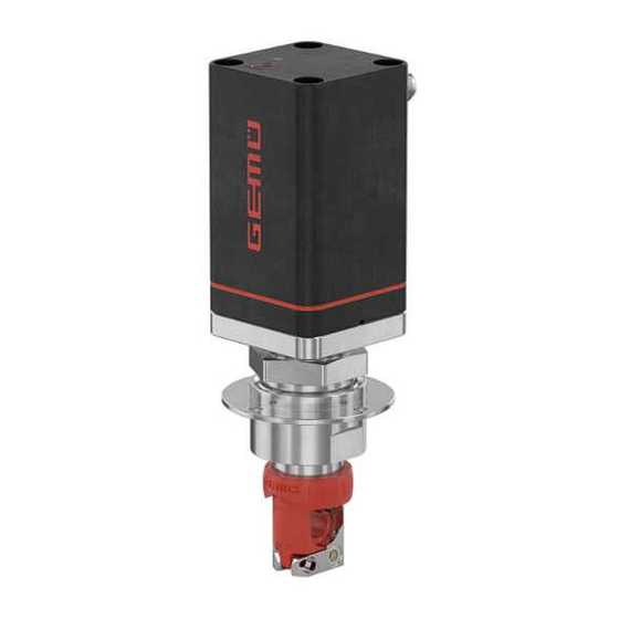
- Page 1 GEMÜ Q51 Elektromotorisch betätigtes Schlauchquetschventil Motorized pinch valve Betriebsanleitung Operating instructions...
- Page 2 Alle Rechte, wie Urheberrechte oder gewerbliche Schutzrechte, werden ausdrücklich vorbehalten. All rights including copyrights or industrial property rights are expressly reserved. Dokument zum künftigen Nachschlagen aufbewahren. Keep the document for future reference. © GEMÜ Gebr. Müller Apparatebau GmbH & Co. KG 25.07.2024 GEMÜ Q51 2 / 48...
-
Page 3: Table Of Contents
18 Rücksendung ............LED-Symbole ..........19 Original EU-Einbauerklärung im Sinne der EG-Ma- Begriffsbestimmungen ......... schinenrichtlinie 2006/42/EG, Anhang II B ... Warnhinweise ..........20 Original EU-Konformitätserklärung gemäß Sicherheitshinweise am Produkt (Beispiel) . 2014/30/EU (EMV-Richtlinie) ....... 2 Sicherheitshinweise ..........3 Produktbeschreibung .......... Aufbau ............ -
Page 4: Hinweise ........................................................ 4 17 Entsorgung
Mögliche Folgen bei Nichtbeachtung. spezifisches Maßnahmen zur Vermeidung der Gefahr. Symbol Warnhinweise sind dabei immer mit einem Signalwort und teilweise auch mit einem gefahrenspezifischen Symbol ge- kennzeichnet. Folgende Signalwörter bzw. Gefährdungsstufen werden einge- setzt: GEMÜ Q51 4 / 48 www.gemu-group.com... -
Page 5: Sicherheitshinweise Am Produkt (Beispiel)
Pos. Symbol Bedeutung 10. Sicherheitshinweise beachten. Quetschgefahr! 11. Das Produkt gemäß diesem Dokument bedienen. - Nicht in den Schlauchquetschbereich 12. Das Produkt entsprechend der Leistungsdaten betreiben. greifen. 13. Das Produkt ordnungsgemäß instand halten. Fehlende oder unleserliche Aufkleber am Produkt müssen an- 14. -
Page 6: Produktbeschreibung
(Beispiel): Ausführung gemäß Bestelldaten gerätespezifische Daten Baujahr - XXXXXXXX|YYYY Artikelnummer Rückmeldenummer fortlaufende Nummer Der Herstellungsmonat ist unter der Rückmeldenummer ver- schlüsselt und kann bei GEMÜ erfragt werden. Das Produkt wurde in Deutschland hergestellt. Position Benennung Werkstoffe Antrieb PA6, glasfaserverstärkt Überwurfmutter Edelstahl Zwischenstück mit Be-... -
Page 7: Funktionsbeschreibung
LED 1 (Grün) LED 2 (Rot) Ventil Power ON Initialisierungsfehler Timeout Pre-Init Mode active alternierend blinkend 2 Hz alternierend blinkend 2 Hz Inititialisierung ready Initialisierung active alternierend blinkend 1 Hz alternierend blinkend 1 Hz Fehler LED Zustände leuchtet blinkt www.gemu-group.com 7 / 48 GEMÜ Q51... -
Page 8: Bestimmungsgemäße Verwendung
Das Produkt ist zur Steuerung eines in einem Schlauch ge- führten Betriebsmediums konzipiert. Das Produkt ist bestimmungsgemäß nicht für den Einsatz in explosionsgefährdeten Bereichen geeignet. ● Das Produkt gemäß den technischen Daten einsetzen. GEMÜ Q51 8 / 48 www.gemu-group.com... -
Page 9: Bestelldaten
6,350 mm (1/4") Außendurchmesser 4 Ausführung Schlauchträger Kunststoff Ausführung, Schlauchträger Edelstahl & Schlauchaufnahme PA 5 Spannung/Frequenz 24 V DC 6 Regelmodul Stellungsregler 7 Montage Variante Mit Befestigungsflansch oben 8 Antriebsausführung Antriebsgröße 0 9 CONEXO Ohne www.gemu-group.com 9 / 48 GEMÜ Q51... -
Page 10: Technische Daten
IP 65 nach EN 60529 Stellgeschwindigkeit: max. 2 mm/s Gewicht: ca. 1,2 kg Mechanische Umweltbe- Klasse 4M8 nach EN 60721-3-4:1998 dingungen: Vibration: 5g nach IEC 60068-2-6 Test Fc Schocken: 25g nach IEC 60068-2-27 Test Ea GEMÜ Q51 10 / 48 www.gemu-group.com... -
Page 11: Einschalt- Und Lebensdauer
7.7.4.1 Istwert als Stromsignal, Regelmodul Code S0 / S1 / S2 Ausgangssignal: 4 - 20 mA Ausgangsart: aktiv Bürde: 650 Ω Kurzschlussfest: 7.7.4.2 Istwert als Spannungssignal, Regelmodul Code V0 / V1 Ausgangssignal: 0 - 10 V Ausgangsart: aktiv www.gemu-group.com 11 / 48 GEMÜ Q51... - Page 12 Hinweise: Das Anfahren der Fehlerposition ist nur bei vollständiger Spannungsversorgung möglich. Dieses Verhalten ist keine Sicherheitsstellung. Damit die Funktion bei Spannungsverlust sicherge- stellt ist, muss das Ventil mit einem Notstrommodul GEMÜ 1571 (siehe Zubehör) betrieben werden. Fehlerposition: Hold - Antrieb verweilt in der angefahrenen Position (Regelmodul S0 und V0) Close - Antrieb fährt in die Geschlossen Position (Regelmodul S1 und V1)
-
Page 13: Abmessungen
ØD1* / ØD2* Ød1 ØD1* ØD2* Ød Ød1 Øk ØL 115,7 50,0 71,0 158,7 39,0 42,0 58,0 30,5 43,0 15,6 49,0 Maße in mm * D1 = Durchmesser ohne Dichtung, D2 = Durchmesser mit Dichtung www.gemu-group.com 13 / 48 GEMÜ Q51... -
Page 14: Ventilkörper, Ohne Befestigungsflansch
8 Abmessungen 8.2 Ventilkörper, ohne Befestigungsflansch Schlauchaußendurchmesser ≤ 1/2" Maße in mm GEMÜ Q51 14 / 48 www.gemu-group.com... -
Page 15: Herstellerangaben
3. Maximale Lagertemperatur nicht überschreiten (siehe Ka- den. pitel „Technische Daten“). HINWEIS 4. Lösungsmittel, Chemikalien, Säuren, Kraftstoffe u. ä. nicht mit GEMÜ Produkten und deren Ersatzteilen in einem Schlauchleitungen fachgerecht verlegen! Raum lagern. ▶ Schlauchleitungen fachgerecht verlegen und nicht unter- 5. Druckluftanschlüsse durch Schutzkappen oder Ver- halb des Mindestbiegeradius biegen, siehe Herstelleran- schlussstopfen verschließen. -
Page 16: Einbaulage
3. Alle Sicherheits- und Schutzeinrichtungen wieder anbrin- gen bzw. in Funktion setzen. 10.4 Montage mit Befestigungsflansch 1. Das Gehäuse vor der Montage des Antriebs gemäß Bohr- bild im Kapitel „Abmessungen“ so bearbeiten, dass der Ventilkörper durch die Aussparung geführt werden kann. -
Page 17: Elektrischer Anschluss
11 Elektrischer Anschluss 11 Elektrischer Anschluss 11.1 Lage der Steckverbinder 11.2 Elektrischer Anschluss Anschluss X1 5-polige M12-Einbaudose, A-kodiert Signalname 24 V Versorgungsspannung I+/U+, Sollwerteingang I+/U+, Istwertausgang Digitaleingang 1 www.gemu-group.com 17 / 48 GEMÜ Q51... -
Page 18: Inbetriebnahme
ð Ventil fährt automatisch in Stellung ZU. werden. ð Ventil fährt automatisch in Stellung AUF. Der Betreiber muss regelmäßige Sichtkontrollen der GEMÜ ð Initialisierungsmodus wird automatisch beendet. Produkte entsprechend den Einsatzbedingungen und dem Ge- ð Ventil fährt den eingestellten Sollwert an. -
Page 19: Ersatzteile
4. Anlage bzw. Anlagenteil gegen Wiedereinschalten sichern. Sicherstellen, dass der Antrieb wäh- ● 5. Anlage bzw. Anlagenteil drucklos schalten. rend des Schlauchwechsels in Offen- 6. GEMÜ Produkte, die immer in derselben Position sind, vier- Position bleibt. mal pro Jahr betätigen. Nicht in den Schlauchquetschbereich ●... -
Page 20: Schlauchaufnahme Demontieren
13.6 Schlauchaufnahme montieren te 20). 3. Antrieb A in Geschlossen-Position bringen. 1. Schlauchaufnahme demontieren (siehe Kapitel 13.3, Sei- te 20). 4. Druckstück 2 nach unten herausziehen. 2. Schlauchaufnahme 1 einsetzen. 3. Befestigungsschraube c mit Innensechskantschlüssel festziehen. GEMÜ Q51 20 / 48 www.gemu-group.com... -
Page 21: Schlauch Einsetzen
Personals ist es erforderlich, dass die Rücksendeer- sichergestellt ist muss das Ventil mit einem Notstrommodul klärung vollständig ausgefüllt und unterschrieben den Ver- GEMÜ 1571 (siehe Zubehör) betrieben werden. sandpapieren beiliegt. Nur wenn diese Erklärung vollständig ausgefüllt ist, wird die Rücksendung bearbeitet. Liegt dem Produkt keine Rücksendeerklärung bei, erfolgt keine Gut-... - Page 22 EN ISO 12100:2010 Teile hieraus) wurden angewandt: Ferner wird erklärt, dass die speziellen technischen Unterlagen gemäß Anhang VII Teil B erstellt wurden. Der Hersteller verpflichtet sich, einzelstaatlichen Stellen auf begründetes Verlangen die speziellen technischen Unterlagen zu der unvollständigen Maschine zu übermitteln. Diese Übermittlung erfolgt elektronisch.
-
Page 23: 2014/30/Eu (Emv-Richtlinie)
20 Original EU-Konformitätserklärung gemäß 2014/30/EU (EMV-Richtlinie) Original EU-Konformitätserklärung gemäß 2014/30/EU (EMV-Richtlinie) Einleitungstext EMV Wir, die Firma GEMÜ Gebr. Müller Apparatebau GmbH & Co. KG Fritz-Müller-Straße 6-8 D-74653 Ingelfingen-Criesbach erklären hiermit in alleiniger Verantwortung, dass das nachfolgend bezeichnete Produkt den Vorschriften der oben genannten Richtlinie entspricht. - Page 24 Disassembling the tube holder ..... 13.4 Disassemble the compressor ....... 13.5 Installing the compressor ......13.6 Assembling the tube holder ......13.7 Insert the tube ..........14 Behaviour in the event of an error ......15 Troubleshooting ..........GEMÜ Q51 24 / 48 www.gemu-group.com...
-
Page 25: General Information
Measures for avoiding danger. down! danger Warning notes are always marked with a signal word and sometimes also with a symbol for the specific danger. The following signal words and danger levels are used: www.gemu-group.com 25 / 48 GEMÜ Q51... -
Page 26: Safety Information On The Product (Example)
The safety information in this document refers only to an indi- vidual product. Potentially dangerous conditions can arise in 15. Consult the nearest GEMÜ sales office. combination with other plant components, which need to be considered on the basis of a risk analysis. The operator is re-... -
Page 27: Product Description
Device-specific data Year of manufacture - XXXXXXXX|YYYY Item number Traceability number Consecutive number The month of manufacture is encoded in the traceability num- ber and can be obtained from GEMÜ. The product was manu- factured in Germany. Item Name Materials Actuator... -
Page 28: Functional Description
LED 2 (red) Valve power ON Initialization error timeout Pre-INIT mode active flash alternately 2 Hz flash alternately 2 Hz Initialization ready Initialization active flash alternately 1 Hz flash alternately 1 Hz Error LED conditions lit (on) flashes GEMÜ Q51 28 / 48 www.gemu-group.com... -
Page 29: Correct Use
The product is designed to control a working medium guided in a tube. The product is not intended for use in potentially explosive areas. ● Use the product in accordance with the technical data. www.gemu-group.com 29 / 48 GEMÜ Q51... -
Page 30: Order Data
Plastic design, stainless steel tube carrier and PA tube holder 5 Voltage/frequency 24 V DC 6 Control module Positioner 7 Mounting option With mounting flange above 8 Actuator version Actuator size 0 9 CONEXO Without GEMÜ Q51 30 / 48 www.gemu-group.com... -
Page 31: Technical Data
Actuating speed: Max. 2 mm/s Weight: Approx. 1.2 kg Mechanical environ- Class 4M8 acc. to EN 60721-3-4:1998 mental conditions: Vibration: 5g acc. to IEC 60068-2-6 Test Fc Shock: 25g acc. to 60068-2-27 Test Ea www.gemu-group.com 31 / 48 GEMÜ Q51... -
Page 32: Duty Cycle And Service Life
7.7.4.1 Actual value as current signal, control module code S0 / S1 / S2 Output signal: 4–20 mA Output type: Active Load resistor: 650 Ω Short-circuit proof: 7.7.4.2 Actual value as voltage signal, control module code V0 / V1 Output signal: 0–10 V Output type: Active GEMÜ Q51 32 / 48 www.gemu-group.com... - Page 33 Notes: Moving to the error position is only possible with full power supply. This behaviour is not a safety position. The valve must be operated with a GEMÜ 1571 emergency power supply module (see accessories) to ensure the function in case of voltage loss.
-
Page 34: Dimensions
Dia. D2* Dia. d Dia. d1 Dia. k Dia. L 115.7 50.0 71.0 158.7 39.0 42.0 58.0 30.5 43.0 15.6 49.0 Dimensions in mm * D1 = diameter without seal, D2 = diameter with seal GEMÜ Q51 34 / 48 www.gemu-group.com... -
Page 35: Valve Body, Without Mounting Flange
8 Dimensions 8.2 Valve body, without mounting flange Tube outside diameter ≤ 1/2" Dimensions in mm www.gemu-group.com 35 / 48 GEMÜ Q51... -
Page 36: Manufacturer's Information
4. Do not store solvents, chemicals, acids, fuels or similar ▶ Lay tube lines professionally and do not bend them below fluids in the same room as GEMÜ products and their spare the minimum bending radius, see manufacturer's inform- parts. -
Page 37: Installation Position
2. Guide the valve body through the recess in the housing. The actuator's mounting flange must be flush with the housing. 3. Connect the mounting flange and housing using appropri- ate screws and washers (not included in the scope of de- livery). www.gemu-group.com 37 / 48 GEMÜ Q51... -
Page 38: Electrical Connection
11 Electrical connection 11.1 Position of the connectors 11.2 Electrical connection Connection X1 Five-pin M12 built-in socket, A-coded Signal name 24 V supply voltage I+/U+, set value input I+/U+, actual value output Digital input 1 GEMÜ Q51 38 / 48 www.gemu-group.com... -
Page 39: Commissioning
The operator must carry out regular visual examination of the ð Initialization mode is automatically ended. GEMÜ products dependent on the operating conditions and ð Valve moves towards the specified set value. the potential danger in order to prevent leakage and damage. -
Page 40: Spare Parts
5. Depressurize the plant or plant component. Do not reach into the tube crushing ● 6. Actuate GEMÜ products which are always in the same po- area. sition four times a year. 1. Move the actuator A to the open position. -
Page 41: Disassembling The Tube Holder
1. Disassemble the tube holder (see “Disassembling the tube holder“, page 41). 4. Pull the compressor 2 out downwards. 2. Insert the tube holder 1. 3. Tighten the fixing screw c using an Allen key. www.gemu-group.com 41 / 48 GEMÜ Q51... -
Page 42: Insert The Tube
Returned goods can be processed only when this note is completed. If no return delivery note is included with the product, GEMÜ cannot process credits or repair work but will dispose of the goods at the operator's expense. - Page 43 EU Declaration of Incorporation according to the EC Machinery Directive 2006/42/EC, Annex II B Machinery Directive introductory text We, the company GEMÜ Gebr. Müller Apparatebau GmbH & Co. KG Fritz-Müller-Strasse 6–8 74653 Ingelfingen Germany hereby declare under our sole responsibility that the below-mentioned product complies with the relevant essential health and safety requirements in accordance with Annex I of the above-mentioned Directive.
-
Page 44: Eu Declaration Of Conformity
2014/30/EU (EMC Directive) EMC introductory text We, the company GEMÜ Gebr. Müller Apparatebau GmbH & Co. KG Fritz-Müller-Strasse 6–8 74653 Ingelfingen-Criesbach, Germany hereby declare under our sole responsibility that the below-mentioned product complies with the regulations of the above-men- tioned Directive. - Page 45 GEMÜ Q51 45 / 48 www.gemu-group.com...
- Page 46 GEMÜ Q51 46 / 48 www.gemu-group.com...
- Page 47 47 / 48 GEMÜ Q51...
- Page 48 GEMÜ Gebr. Müller Apparatebau GmbH & Co. KG Fritz-Müller-Straße 6-8, 74653 Ingelfingen-Criesbach, Germany Änderungen vorbehalten Phone +49 (0) 7940 1230 · info@gemue.de Subject to alteration www.gemu-group.com 07.2024 | 88913108...
Need help?
Do you have a question about the Q51 and is the answer not in the manual?
Questions and answers