Lexicon MC-8 User Manual
Digital controller
Hide thumbs
Also See for MC-8:
- User manual (171 pages) ,
- Software upgrade instructions (20 pages) ,
- Specifications (4 pages)
Table of Contents
Advertisement
Quick Links
Advertisement
Table of Contents
Troubleshooting

Related Manuals for Lexicon MC-8


Summary of Contents for Lexicon MC-8
- Page 1 MC-8 Digital Controller User Guide...
-
Page 2: Important Safety Instructions
IMPORTANT SAFETY INSTRUCTIONS Read these instructions. 12. Use only with the cart, stand, tripod, bracket, or • Never attach audio power amplifier outputs directly table specified by the manufacturer, or sold with the to any of the unit’s connectors. Keep these instructions. apparatus. - Page 3 Sales Fax: 781-280-0495 Lexicon, Logic 7 and the L7 logo are registered trademarks of Harman International Industries, Inc. U.S. Patent Nos. D454,553; D454,860; 5,796,844; 5,870,480 and other worldwide patents issued and pending. Lexicon LIVE is a trademark of Harman Interna-...
-
Page 4: Documentation Conventions
DOCUMENTATION CONVENTIONS This document contains general safety, installation and operation instructions for the MC-8 and MC-8 Balanced Digital Controllers. It is impor- tant to read this user guide before attempting to use the product. Pay particular attention to safety instructions. -
Page 5: Table Of Contents
INPUT SELECT Parameter Settings ........3-19 ZONE2 in Parameter Settings ..........3-21 Getting Started Speaker Setup ................. 3-22 About the MC-8 ................ 1-2 Setting Crossover Points ............3-22 Highlights ................1-4 Speaker Setup Parameters ........... 3-26 Product Registration ..............1-5 Calibrating Speaker Distances and Output Levels .... - Page 6 Introduction Lexicon Routine Maintenance..............6-4 Restoring Factory-Default Settings ..........6-4 Appendix Specifications................A-2 Declaration of Conformity ............A-4 Menu Tree.................A-5 Installation Worksheet .............A-20...
-
Page 7: Getting Started
Getting Started About the MC-8 ................. 1-2 Highlights ....................1-4 Product Registration ..............1-5 Installation Considerations............1-5 Remote Control Battery Installation ..........1-6... -
Page 8: About The Mc-8
Because the improvement it provides is clearly audible, LOGIC 7 The MC-8 is one of the most advanced audio and video control decoding is widely regarded as the finest available. - Page 9 A digital audio pass through output is available for recording digital signals with a CD Built to professional standards, the MC-8 is designed to serve as the recorder or a similar component. control center in any high-quality home theater. Even the most...
-
Page 10: Highlights
• LIVE! (Lexicon Intelligent Variable input connectors • Balanced audio output connectors for all Environment) Main Zone and Zone 2 channels (MC-8 • Auto switching between digital and • Dolby Digital Surround EX, Dolby Pro Balanced only) analog audio input connectors Logic IIx, and Dolby Pro Logic decoding •... -
Page 11: Product Registration
Pay particular attention to instructions below and to such as a power amplifier. other precautions that appear throughout this user guide. install the MC-8 on a solid, flat, level surface such as a table or shelf. The MC-8 can also be installed in a standard 19-inch CAUTION! -
Page 12: Remote Control Battery Installation
The remote control requires two AA batteries. The batteries should be replaced as needed. Alkaline batteries, which last longer without leaking, are recommended. When battery power is low, the remote control enters a low-voltage condition, preventing it from operating the MC-8. -
Page 13: Basic Operation
Basic Operation Front Panel Overview ..............2-2 Rear Panel Overview..............2-6 Remote Control Overview ............2-10 Operation Considerations................ 2-10 MAIN Menu .................... 2-10 Menu Navigation ................... 2-10 Menu Item Selection ................2-11 Command Bank Activation..............2-13 Command Matrix ................... 2-14 Understanding the Zones ............ -
Page 14: Front-Panel Overview
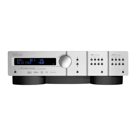
FRONT-PANEL OVERVIEW The MC-8 is shown below. The MC-8 Balanced is shown on page 2-4. The front panels are identical, except the MC-8 Balanced has a larger chassis. The numbers in the front-panel illustrations correspond with the numbered items in the text. -
Page 15: Volume Knob
The red LED lights when the A/D converters are overloading. selection button, rotate the volume knob • The blue LED lights when the MC-8 is powered on and clockwise to increase or counterclockwise activated – even if the FRONT PANEL DISPLAY menu STATUS to decrease volume level in 1dB increments. - Page 16 FRONT-PANEL OVERVIEW (continued) The MC-8 Balanced, shown below, has a larger chassis than the MC-8, shown on page 2-2. Otherwise, they are identical. The numbers in the front-panel illustrations correspond with the numbered items in the text. 6 MUTE BUTTON Mutes or restores the MC-8 Main Zone volume to its original level.
- Page 17 Basic Operation MC-8 7 MAIN ZONE INPUT SELECTION BUTTONS 9 ZONE 2 INPUT SELECTION BUTTONS Selects the corresponding input in the Main Zone. When an input is Selects the corresponding input in Zone 2. When an input is selected, a blue LED lights on the corresponding input selection selected, an amber LED lights on the corresponding input selection button.
-
Page 18: Rear-Panel Overview
REAR-PANEL OVERVIEW The MC-8 is shown below. The MC-8 Balanced, shown on page 2-8, includes balanced audio output connectors for the Main Zone and Zone 2. Otherwise, both models are identical. The numbers in the rear-panel illustrations correspond with the numbered items in the text. - Page 19 1 to 3 are available. The component video connectors are not available for Zone 2. 7 POWER SWITCH Use the Power switch to power the MC-8 on or off. The I and O 4 MAIN ZONE VIDEO OUTPUT CONNECTORS positions represent “on” and “off” status, respectively. When the Provide video output in the Main Zone.
- Page 20 (continued) The MC-8 is shown on page 2-6. The MC-8 Balanced, shown below, includes balanced analog audio output connectors for the Main Zone and Zone 2. Otherwise, both models are identical. The numbers in the rear-panel illustrations correspond with the numbered items in the text.
- Page 21 5.1-channel connectors. The PWR connector – the power trigger output connector – is not configurable. It is activated when the MC-8 is activated, and deacti- When a 5.1-channel analog audio source is present in the Main Zone, vated when the MC-8 is deactivated. The trigger output connector (1) input signals are sent to the Main Zone audio output connectors, as can be configured for remote or program operation.
-
Page 22: Remote Control Overview
IR receiver. • For optimal performance, position the remote control at a 30-degree angle no more than 17 feet (5m) from the MC-8. Placing the MC-8 inside a smoked glass cabinet will reduce the remote control range. -
Page 23: Menu Item Selection
Basic Operation MC-8 MENU ITEM SELECTION Use the remote control Menu arrows to navigate menus and to select menu items. Arrow Navigation Functions • When a menu is open, press the arrow button to select the highlighted menu item. • When no menus are open, press the arrow button to open the MAIN MENU. - Page 24 Basic Operation Lexicon MENU PARAMETERS HORIZONTAL BAR GRAPHS Selecting a menu parameter opens a drop-down menu or Selecting some menu parameters opens a horizontal bar graph. The horizontal bar graph that is used to select the desired setting. bar graph indicates the position at which the current parameter setting falls within the entire parameter range.
-
Page 25: Command Bank Activation
The Zone 2 and Shift buttons themselves do not send commands to A “Z” appears when a command from the Zone 2 command bank the MC-8. When pressed and held, these buttons activate the was received last. An “S” appears when a command from the Shift associated command bank. -
Page 26: Command Matrix
Main Zone Zone 2 Shift Blue Deactivates standby mode and Reserved for future possibilities. Reserved for future possibilities. Stat activates the MC-8. Shift Zone 2 Activates standby mode and Deactivates Zone 2. Deactivates the Main Zone. Menu deactivates the MC-8. - Page 27 1dB increments. increments. 3dB increments. Music 2 CH MC-8 Digital Controller Toggles between lowering Toggles between fully muting Toggles between fully muting Main Zone volume level Z o n e 2 v o l u m e l e v e l a n d...
- Page 28 Tuner Main Zone. Zone 2. C O N T R O L S m e n u T I LT E Q MC-8 Digital Controller parameter in 0.2dB increments. Selects the AUX input for the Selects the AUX input for Sets the AUDIO CONTROLS Main Zone.
- Page 29 Reserved for future Adjusts the MAIN ADV menu INPUT playback. possibilities. SELECT parameter, cycling through the MC-8 Digital Controller ANALOG, DIGITAL and AUTO settings. Toggles between the current Reserved for future Toggles the MAIN ADV menu 2-CH l i s t e n i n g m o d e a n d t h e 2 - possibilities.
-
Page 30: Understanding The Zones
These zones have separate digital audio receivers and dedicated analog source selectors that allow for independent input selection in each zone. For instance, the MC-8 can play a DVD in the Main Shift-DTS Zone and a CD in Zone 2 at the same time. -
Page 31: Two-Line Status
The two-line status opens in the on-screen and front-panel displays Activate the Shift command bank and press the remote control whenever the MC-8 detects a change in input source or listening Stat button to open the STATUS menu for the current input source. -
Page 32: Status Menu Descriptions
Basic Operation Lexicon STATUS MENU DESCRIPTIONS D STATUS The table beneath each description lists the possible settings for Provides information about Dolby Digital input sources. Features each parameter. L, C, R, SL, SR and LFE level meters. Parameter Possible Settings... - Page 33 Basic Operation MC-8 STATUS 5.1a BYPASS STATUS Provides information about DTS-ES input sources. Includes L, C, R, Provides information about 5.1-channel analog input sources when SL, SR, SB and LFE level meters. The SB level meter appears when a the MAIN ADV menu ANALOG BYPASS parameter is set to ON.
- Page 34 Basic Operation Lexicon 2CH BYPASS STATUS DIGITAL STATUS Provides information about 2-channel analog input sources when Provides information about digital input sources for which a sample the MAIN ADV menu 2-CH ANLG BYP parameter is set to ON. rate is detected, but no audio is present in the input signal.
- Page 35 Basic Operation MC-8 LIVE! STATUS Provides information about LIVE! input sources. Features L and R level meters. Parameter Possible Settings INPUT The current input MODE The current listening mode INPUT TYPE SAMPLE RATE 48kHz See “STATUS Menu Parameter Descriptions” on page 2-24...
-
Page 36: Status Menu Parameter Descriptions
DIALOG OFFSET parameter indicates the Indicates the rate at which the input signal is encoded. A higher bit amount of adjustment the MC-8 makes to normalize dialog to –27dBFS. rate indicates that less compression was used during the encoding process. -
Page 37: Status Menu Level Meters
Basic Operation MC-8 INPUT SURR MIX LVL +0.0dB, –3.0dB, –6.0dB Indicates the selected input (e.g., DVD1). Indicates the relative surround channel level that was used during the mixing process. INPUT TYPE ANLG, BYP, PCM, MIC, --- WORD LENGTH 16 bits, 20 bits, 24 bits Indicates the input source that is present. -
Page 39: Setup
Setup Setup ..................3-2 Input Setup.................3-4 Changing Input Names................3-5 Assigning Audio and Video Input Connectors ........... 3-7 Selecting Preferred Listening Modes............3-12 Configuring Advanced Input Settings............3-17 INPUT SELECT Parameter Settings............3-19 ZONE2 in Parameter Settings..............3-21 Speaker Setup ................3-22 Setting Crossover Points................ -
Page 40: Setup
Setup Lexicon SETUP Selecting SETUP from the MAIN MENU opens the SETUP menu. REAR PANEL CONFIG SETUP REAR PANEL CONFIG MAIN MENU SETUP Opens the REAR PANEL CONFIG menu, which is used to configure MODE ADJUST INPUTS the analog audio input connectors as eight stereo connectors, one... - Page 41 Setup MC-8 LOCK OPTIONS LIVE! CALIBRATION SETUP LOCK OPTIONS SETUP LIVE! CALIBRATION Opens the LOCK OPTIONS menu, which is used to protect MODE Opens the LIVE! CALIBRATION menu, which is used to perform the ADJUST, AUDIO CONTROLS and SETUP menu branch settings from necessary calibration before using the LIVE! modes.
-
Page 42: Input Setup
Setup Lexicon INPUT SETUP SETUP INPUTS DVD1 INPUT SETUP Selecting the SETUP menu INPUTS option prompts the selection of a desired input (e.g., DVD1). Selecting an input opens the corresponding INPUT SETUP menu, which is used to change the input name, assign audio and video input connectors, select preferred listening modes and configure advanced Main Zone and Zone 2 input settings. -
Page 43: Changing Input Names
Setup MC-8 CHANGING INPUT NAMES Selecting the INPUT SETUP menu NAME parameter opens the INPUT NAME menu, which is used to customize or restore the factory-default name of the selected input. Factory-default input names correspond to front-panel and remote control input selection button labels. - Page 44 Setup Lexicon SETUP INPUT SETUP DVD1 INPUT NAME PRESS MENU V TO DVD1 INPUT SETUP MAIN MENU RESTORE INPUT NAME INPUTS DVD1 EDIT INPUT NAME MODE ADJUST NAME DVD1 SPEAKERS DVD2 RESTORE DEFAULT NAME AUDIO CONTROLS DIGITAL IN COAX-1 REAR PANEL CONFIG...
-
Page 45: Assigning Audio And Video Input Connectors
MC-8 ASSIGNING AUDIO and VIDEO INPUT CONNECTORS The MC-8 has eight configurable inputs, each of which can be assigned to its eight digital audio, eight analog audio, five composite video, five S-Video or three component video input connectors. DVD1 DIGITAL IN... - Page 46 ANALOG IN Opens the ANALOG IN menu, which is used to assign an analog Please note the following: audio input connector for the selected input. The MC-8 has eight • When no analog audio input connector is assigned, the MC-8...
- Page 47 To analog audio input connector assigned for the selected input. When compensate for this, the MC-8 allows independent input level another stereo analog audio input connector is assigned, these adjustment for each of its stereo analog audio input connectors.
- Page 48 When set to ON, the MC-8 automatically monitors and selected stereo analog audio input connector. When the ANLG IN optimizes input levels. When the input signal is too high, the MC-8 LVL menu AUTO parameter is ON, the AUTO GAIN parameter quickly decreases input levels to avoid overload.
- Page 49 Opens the VIDEO IN menu, which is used to assign a composite or Opens the COMPONENT IN menu, which is used to assign a S-Video input connector for the selected input. The MC-8 has eight component video input connector for the selected input. The MC-8...
-
Page 50: Selecting Preferred Listening Modes
Selects a preferred listening mode for Dolby Digital sources The MC-8 allows five preferred listening modes for each Main Zone Selects a preferred listening mode for DTS(-ES) sources input: one listening mode each for 2-channel, Dolby Digital, DTS(-ES), and MIC (LIVE!) sources. - Page 51 For example, many of the dynamic modes are only available when Modes are available through the remote control or front panel Mode the MC-8 is configured for seven main output channels and source button. The dynamic listening modes are listed in the table below.
- Page 52 When the MC-8 is set to use a preferred listening mode for a selected input, selecting another mode from the Mode scroll list replaces the When USE LAST is selected as the preferred listening mode, and a preferred selection.
- Page 53 Since Dolby PLIIx MOV is a dynamic listening mode, it cannot be selected as the preferred listening mode for Dolby Digital The MC-8 activates a DTS NEO:6 listening mode if a DTS NEO:6 sources. listening mode was activated the last time a 2-channel source was present, and a 44.1kHz or 48kHz PCM digital source is present.
- Page 54 When the MIC parameter is set to USE LAST: When the DTS-ES parameter is set to USE LAST: The MC-8 activates the listening mode (LIVE! SMALL, LIVE! MED or LIVE! LARGE) that was activated the last time a MIC source was •...
-
Page 55: Configuring Advanced Input Settings
AUTO, OFF Note: S-Video OSD 4:3 ON, OFF When the INPUT SELECT parameter is set to AUTO, the MC-8 will not COMPONENT OSD ON, OFF select the assigned analog audio input connector when a valid digital audio input source is present. Some DVD and CD players output digital signals (data) when the player is paused or stopped or when the player is powered on and the disc drawer is empty. - Page 56 Main Zone audio output connectors. When a video input signals to pass through the S-Video switcher, enabling 5.1-channel analog audio source is present, the MC-8 passes only (L) compatible display devices to automatically switch between and (R) analog audio input signals to the Main Zone audio output anamorphic and non-anamorphic display modes.
-
Page 57: Input Select Parameter Settings
INPUT SELECT PARAMETER SETTINGS DIGITAL ANALOG AUTO The MC-8 sends the assigned digital audio The MC-8 sends the assigned analog audio The MC-8 toggles between sending the assigned input connector to the Main Zone audio input connector to the Main Zone audio output digital and analog audio output input connectors output connectors. - Page 58 ZONE2 IN parameter settings. Caution! When the ZONE2 IN parameter is set to DIGITAL or ANLG, the MC-8 recognizes some DTS-encoded sources as audio signals (not data signals) and outputs loud digital noise from the Zone 2 audio output connectors.
-
Page 59: Zone2 In Parameter Settings
DMIX (Downmix) The MC-8 automatically sets the The MC-8 automatically sets the The MC-8 sends a downmixed version of Main Zone audio to the ZONE2 IN parameter to DIGITAL ZONE2 IN parameter to ANLG Zone 2 audio output connectors. Downmixes can be generated for... -
Page 60: Speaker Setup
Setup Lexicon SPEAKER SETUP SETUP SPEAKERS Select the SPEAKER SETUP menu to configure the Main Zone audio output connectors for the desired speaker setup. The Main Zone includes eight audio output connectors labeled Front L/R, Center, Subwoofer, Side L/R and Rear L/R. - Page 61 Setup MC-8 CROSSOVER SETUP CUSTOM SETUP MAIN MENU SETUP SPEAKER SETUP FRONT L/R 40 Hz INPUTS CUSTOM SETUP MODE ADJUST SET CROSSOVERS CENTER 60 Hz SPEAKERS THX SETUP AUDIO CONTROLS CHECK MICROPHONES SIDE L/R 60 Hz REAR PANEL CONFIG SETUP...
- Page 62 Setup Lexicon SETTING CROSSOVER POINTS (continued) High-Pass Filter Low-Pass Filter High-pass filters attenuate low frequencies at 24dB per octave. The curves in the graph Low-pass filters attenuate high frequencies at 24dB per octave. The curves in the graph above indicate the frequency response of each crossover setting. From left to right, the above indicate the frequency response of each crossover setting.
- Page 63 SPEAKERS SET CROSSOVERS THX SETUP When a THX speaker setup is selected, the MC-8 applies a THX 80Hz Selecting CROSSOVER SETUP THX SETUP opens the THX SPEAKER crossover point with a 12dB-per-octave filter to the Front L/R, Center, SETUP screen, which indicates that pressing the arrow button will Side L/R and Rear L/R output connectors.
-
Page 64: Speaker Setup Parameters
Setup Lexicon SPEAKER SETUP PARAMETERS SETUP SPEAKERS SET CROSSOVERS CUSTOM SETUP SETUP SPEAKERS SET CROSSOVERS THX SETUP The table below indicates the speaker setup parameters for config- Speaker setup parameters perform the same function regardless of uring the Main Zone audio output connectors for the desired speaker the selected speaker setup. - Page 65 Setup MC-8 CUSTOM SETUP MAIN MENU SETUP SPEAKER SETUP CUSTOM SETUP CROSSOVER SETUP FRONT L/R 40Hz INPUTS SET CROSSOVERS CUSTOM SETUP 40 Hz MODE ADJUST CENTER 60Hz SPEAKERS CHECK MICROPHONES THX SETUP 60 Hz AUDIO CONTROLS SIDE L/R 60Hz REAR PANEL CONFIG...
- Page 66 Setup Lexicon SPEAKER SETUP PARAMETERS (continued) FRONT L/R CENTER FULL, FULL + SUB, 30 to 120HZ, THX 80HZ FULL, FULL + SUB, 30 to 120HZ, THX 80HZ, NONE SETUP SPEAKERS SET CROSSOVERS CUSTOM SETUP CENTER SETUP SPEAKERS SET CROSSOVERS CUSTOM SETUP...
- Page 67 Side L/R output connectors. If connectors. If the REAR L/R parameter is also set to NONE, the the SIDE L/R parameter is also set to NONE, the MC-8 redirects MC-8 will redirect surround channel signals to the Front L/R surround channel signals to the Front L/R output connectors.
- Page 68 Assigns a crossover point for the Main Zone audio output connector Note: labeled Subwoofer. When set to FULL, the MC-8 sends a full-range When the SUBWOOFER parameter is set to NONE, subwoofer signals will audio output signal to this connector. Otherwise, the MC-8 activates not be redirected if the 5.1a BYPASS listening mode is activated.
- Page 69 Setup MC-8 MAIN MENU SETUP SPEAKER SETUP CUSTOM SETUP CROSSOVER SETUP INPUTS SET CROSSOVERS CUSTOM SETUP 40 Hz MODE ADJUST SPEAKERS CHECK MICROPHONES THX SETUP 60 Hz AUDIO CONTROLS REAR PANEL CONFIG AUTOMATIC 60 Hz SETUP DISPLAYS MANUAL 60 Hz...
- Page 70 When the remote control 7/5 button is used to toggle between 7 and 5-channel playback: • ASA processing is not available during 5-channel playback. • The MC-8 automatically switches between the 5.1 THX ULTRA2 and 5.1 THX or DTS THX ULTRA2 and DTS THX listening modes. 3-32...
-
Page 71: Calibrating Speaker Distances And Output Levels
CALIBRATING SPEAKER DISTANCES and OUTPUT LEVELS The MC-8 offers both automatic and manual calibration of speaker distances and output levels. Calibration helps to ensure accurate output signal arrival time and level at the primary listening position. However, it is not a substitute for proper speaker placement. - Page 72 UNITS Determines the unit of measurement in which speaker distances are calculated on ALL speaker distance menus. When FEET is selected, the MC-8 calculates speaker distances in feet. When METERS is selected, the MC-8 calculates speaker distances in meters. When the UNITS parameter setting is adjusted, the MC-8 automatically adjusts speaker distances to the closest available value in the selected unit of measurement.
-
Page 73: Automatic Calibration
Setup MC-8 AUTOMATIC CALIBRATION The MC-8 offers automatic calibration of speaker distances, output level, or both. The table below indicates available automatic calibration options. A successful microphone check is required before automatic calibration can be performed. Automatic Options Details MICROPHONE CHECK •... -
Page 74: Troubleshooting
Lexicon Microphone Kit, available at authorized Lexicon dealers. Performing automatic calibration with microphones other than 1. Make sure the MC-8 is powered off OR in standby mode. those in the kit will produce unpredictable results. A separate kit includes a microphone board assembly which is installed in one 2. - Page 75 Setup MC-8 POSITIONING THE MICROPHONES FOR THE MICROPHONE CHECK Refer to the microphone placement examples that begin below to position the microphones for the microphone check. PROPER microphone positioning for the microphone check During the microphone check, position the microphones:...
- Page 76 Setup Lexicon IMPROPER microphone positioning for the microphone check During the microphone check, DO NOT: 7 Separate the microphones 7 Scatter the microphones throughout the listening space 7 Obstruct the line-of-sight path between the micro- phones and the speakers Rear...
- Page 77 The following screens appears in the on-screen display as the micro- • The MC-8 outputs calibration noise signals between 55dB and phone check is performed: 95dB, beginning with 55dB and increasing in 5dB increments until the microphones detect the required level.
- Page 78 A message similar to the one shown at the bottom of the previous column opens in the on-screen display. The MC-8 uses the calibration noise signal to eliminate micro- Refer to the table on the next page for information about all phones that register the signal at a level that is too low or too possible microphone check messages.
- Page 79 The MC-8 did not detect the micro- • Examine microphone input connections to ensure that the microphones are properly con- (MICROPHONE) nected to the MC-8 and that microphone cable plugs are fully inserted for a solid connection. phone during the silence check. NOT DETECTED •...
- Page 80 Microphone single listening position. The microphones are Center positioned as close together as possible in a single listening position, allowing the MC-8 to calibrate Subwoofer optimal speaker distances and output levels for that Front Right position.
- Page 81 Each micro- Microphone phone is positioned in a single listening position within a Center single row, allowing the MC-8 to calibrate optimal speaker distances and output levels for that row at the Subwoofer expense of a single listening position.
- Page 82 Each micro- Microphone phone is positioned in a single listening position within a Center row, allowing the MC-8 to calibrate optimal speaker distances and output levels for a larger listening area at Subwoofer the expense of a single listening position.
- Page 83 Subwoofer check. The microphones are positioned on the floor Front along the perimeter of the listening space, making it Right difficult for the MC-8 to calibrate optimal speaker distances and output levels for the actual listening positions. 3-45...
- Page 84 Setup Lexicon POSITIONING THE MICROPHONES FOR AUTOMATIC CALIBRATION (continued) IMPROPER microphone positioning for automatic calibration During the automatic calibration, do not: 7 Arrange the microphones along the perimeter of the listening positions or space 7 Position the microphones at spots where the listeners’...
-
Page 85: Performing Automatic Calibration
The following AUTO SPEAKER SETUP messages are displayed before automatic calibration begins: • The !CAUTION! HIGH AUDIO LEVELS message indicates that the MC-8 generates loud calibration noise signals during automatic calibration. If the sig- nals become too loud, press the arrow button to cancel automatic calibration. - Page 86 MC-8 calculates a distance for the corresponding speaker. As it finishes each parameter, the MC-8 enters the calibrated value or an ERROR message to the right of the parameter label. • Because of the way low-frequency signals propagate in most listening spaces, automatic speaker dis- tance calibration often produces unreliable results for subwoofers.
- Page 87 SIDE LEFT -4.5dB SIDE LEFT 4.5ft SUBWOOFER SUBWOOFER When the MC-8 is finished calibrating speaker distances and output levels, the AUTO SPEAKER SETUP screen is displayed, indicating the results for each calibration procedure. When the MC-8 is finished calibrating When the MC-8 is finished calibrating speaker distances, the AUTO DISTANCES •...
- Page 88 Setup Lexicon PERFORMING AUTOMATIC CALIBRATION (continued) STEP DISTANCES DISTANCES & LEVELS LEVELS SET DISTANCES AUTO DISTANCES AUTO SPEAKER SETUP AUTO DISTANCES* SET LEVELS AUTO LEVELS AUTO DISTANCES FRONT LEFT 12.0ft DISTANCES FRONT LEFT 12.0ft AUTO LEVELS FRONT LEFT -2.0dB ORIGINAL DISTANCES CENTER 10.5ft...
- Page 89 • Set the corresponding CUSTOM or THX SETUP menu parameter to include the selected (SPEAKER) speaker in the speaker setup. (The MC-8 only calibrates values for speakers that are included in speaker setup. SPEAKER IS NOT ENABLED the speaker setup.) The microphones detected out-of-phase •...
-
Page 90: Manual Calibration
Setup Lexicon MANUAL CALIBRATION SETUP SPEAKERS MANUAL Selecting the SPEAKER SETUP menu MANUAL option displays the MANUAL SPEAKER SETUP menu, to manually calibrate speaker distances and output levels. The table below indicates available manual calibration options. MAIN MENU SETUP SPEAKER SETUP... - Page 91 Setup MC-8 PERFORMING MANUAL SPEAKER DISTANCE CALIBRATION SETUP SPEAKERS MANUAL SPEAKER DISTANCES Selecting the MANUAL SPEAKER SETUP menu SPEAKER DISTANCES option displays the SPEAKER DISTANCES menu, to manually calibrate speaker distances. SETUP MAIN MENU SPEAKER SETUP MANUAL SPEAKER SETUP CUSTOM SETUP...
- Page 92 Setup Lexicon PERFORMING MANUAL OUTPUT LEVEL CALIBRATION SETUP SPEAKERS MANUAL LEVELS CALIBRATION Selecting the MANUAL SPEAKER SETUP menu LEVELS CALIBRATION option displays the LEVELS CALIBRATION menu shown below, to manually calibrate output levels. SETUP LEVELS CALIBRATION MAIN MENU SPEAKER SETUP...
- Page 93 Note: During the internal noise test, the MC-8 sends calibration noise During the internal noise test, it is possible to select an output level signals to each speaker in the order shown on the SPEAKER LEVEL parameter just as the cursor is about to automatically scroll to the ADJUST menu.
- Page 94 The external noise test requires an external calibration source such as an audio calibration disc. When the external noise test is conducted, the MC-8 activates a listening mode based on the current Main Zone To manually calibrate output levels during the external noise test: input source.
- Page 95 The BASS PEAK LIMITERS option displays the BASS PEAK LIMITERS menu, to set amplitude limits on low-frequency signals sent to the Main Zone audio output connectors, including the Subwoofer. The MC-8 is equipped with an internal limiter to prevent low-frequency signals from exceeding a designated output level.
- Page 96 Setup Lexicon SETTING BASS PEAK LIMITERS (contined) LIMIT ADJ 75 to 120dB SUB LIMITER ON, OFF SETUP SPEAKERS MANUAL LEVELS CALIBRATION BASS PEAK LIMITERS SETUP SPEAKERS MANUAL LEVELS CALIBRATION BASS PEAK LIMITERS LIMITER ADJ SUB LIMITER Sets amplitude limits applied to the Subwoofer output connector,...
-
Page 97: Rear-Panel Configuration
Setup MC-8 REAR-PANEL CONFIGURATION SETUP REAR PANEL CONFIG The REAR PANEL CONFIG option is used to configure the analog audio input connectors as eight (Left/Right) stereo connectors, five (Left/Right) stereo connectors and one 5.1-channel configuration (Front L/R, Center, Subwoofer, Side L/R), or as two stereo connectors and two 5.1-channel configurations. - Page 98 Setup Lexicon 5 ST. & 5.1 ANLG 2 ST. & (2) 5.1 ANLG SETUP REAR PANEL CONFIG 2 ST. & (2) 5.1 ANLG SETUP REAR PANEL CONFIG 5 ST. & 5.1 ANLG Configures the analog audio input connectors as two stereo Configures the analog audio input connectors as five stereo connectors and two 5.1-channel configurations.
-
Page 99: Display Setup
Setup MC-8 DISPLAY SETUP SETUP DISPLAYS Selecting the SETUP menu DISPLAYS option opens the DISPLAY SETUP menu, which is used to customize the on-screen and front-panel displays, restore audio/video synchronization, and activate and create a custom unit name. MAIN MENU... - Page 100 MC-8 is activated. character above the cursor (^). When set to OFF, the custom name does not appear when the MC-8 is activated. The custom name can be entered in the DISPLAY SETUP 3.
- Page 101 When set to 2 SECONDS, the on-screen display FORMAT NTSC SECAM, PAL, NTSC appears for 2 seconds whenever the input source changes or the MC-8 BACKGROUND ON ON, OFF receives a command. When set to ALWAYS OFF, the on-screen display...
- Page 102 The FORMAT parameter affects the composite and S-Video output the last command bank from which the MC-8 received a command. connectors. It does not affect the component video output connector.
- Page 103 ON, the front-panel display remains on at all times. When set to 2 SECONDS, the front-panel display appears for 2 seconds whenever the input source changes or the MC-8 receives a command. When set to ALWAYS OFF, the front-panel display remains off at all times.
-
Page 104: Volume Control Setup
Setup Lexicon VOLUME CONTROL SETUP SETUP VOLUME CONTROLS Opens the VOLUME CONTROL SETUP menu, which is used to configure Main Zone and Zone 2 volume levels. VOLUME CONTROL SETUP MAIN MENU SETUP VOLUME CONTROL SETUP LAST LVL, -80 to +12dB... -
Page 105: Trigger Setup
8 rear panel houses two 12V DC trigger output connectors. ZONE2 INPUTS The connector labeled PWR – the power trigger output FILM connector – is not configurable. It is activated when the MC-8 * TRIGGER SETUP menu MUSIC listening mode names is activated, and deactivated when the MC-8 is deactivated. - Page 106 Setup Lexicon PROGRAM OPERATION PARAMETERS ON, OFF TRIGGER SETUP SETUP MAIN MENU TRIGGER SETUP SETUP TRIGGER (PROGRAM OPERATION PARAMETER) INPUTS REMOTE ONLY MODE ADJUST MUSIC SPEAKERS DVD1 AUDIO CONTROLS DVD2 REAR PANEL CONFIG SETUP Configure the trigger output connector labeled 1 for...
-
Page 107: Lock Options
Setup MC-8 LOCK OPTIONS SETUP LOCK OPTIONS Selecting the SETUP menu LOCK OPTIONS option opens the LOCK OPTIONS menu, which is used to protect MODE ADJUST, AUDIO CONTROLS and SETUP menu branch parameter settings from accidental changes. MAIN MENU SETUP... -
Page 108: Live! Calibration
2. Connect the Lexicon microphones to the microphone input 1 and LOUDNESS parameter is shown as set to OFF. 2 connectors on the MC-8 rear panel. Connector 1 is for the left microphone, connector 2 is for the right. If microphones are... - Page 109 Setup MC-8 POSITIONING THE MICROPHONES FOR LIVE! Refer to the microphone placement examples below to position the microphones for LIVE! PROPER microphone positioning for LIVE! Position the microphones: 3 On or near opposite side walls 3 Approximately halfway between the front and...
- Page 110 Setup Lexicon IMPROPER microphone positioning for LIVE! When positioning the microphones, DO NOT: 7 Place the microphones on the front or rear walls 7 Place the microphones near the floor or ceiling Rear Left 7 Obstruct the microphones with furniture or other...
-
Page 111: Audio Controls
2. The !CAUTION! HIGH AUDIO LEVELS message appears to indicate phones failed to pick up sufficient calibration noise signals that the MC-8 generates loud calibration noise signals during LIVE! for calibration to complete. calibration. If the signals become too loud, press the button to 4. -
Page 113: Audio Controls
Audio Controls Audio Controls ................4-2... - Page 114 Audio Controls Lexicon AUDIO CONTROLS Selecting the MAIN MENU AUDIO CONTROLS option opens the AUDIO CONTROLS menu, which is used to customize the Main Zone audio output connectors and to control the balance of the Zone 2 audio output connectors. The BASS, TREBLE, TILT EQ, LOUDNESS, BALANCE and FADER parameters affect the Main Zone audio output connectors, including all Main Zone inputs and listening modes, except the 5.1a BYPASS and...
- Page 115 Audio Controls MC-8 BASS Parameter Settings TREBLE Parameter Settings The BASS parameter controls the amount of low-frequency boost or cut applied to the The TREBLE parameter controls the amount of high-frequency boost or cut Main Zone audio output connectors labeled Front L/R, Center and Subwoofer.
-
Page 116: Mode Adjust Mode Adjust
Audio Controls Lexicon AUDIO CONTROLS (continued) MAIN MENU AUDIO CONTROLS MAIN MENU AUDIO CONTROLS -3.0 to +3.0dB BASS BASS MODE ADJUST MODE ADJUST TREBLE TREBLE AUDIO CONTROLS AUDIO CONTROLS TILT EQ TILT EQ SETUP SETUP LOUDNESS LOUDNESS BALANCE BALANCE FADER... - Page 117 Audio Controls MC-8 TILT EQ Parameter Settings LOUDNESS Parameter Settings The TILT EQ parameter controls the amount of tilt equalization applied to the Main The LOUDNESS parameter controls the amount of low-frequency boost that is Zone audio output connectors labeled Front L/R, Center and Subwoofer.
- Page 118 Audio Controls Lexicon AUDIO CONTROLS (continued) MAIN MENU AUDIO CONTROLS MAIN MENU AUDIO CONTROLS L< ZONE2 BALANCE >R L< BALANCE >R MODE ADJUST BASS MODE ADJUST BASS TREBLE TREBLE AUDIO CONTROLS AUDIO CONTROLS TILT EQ TILT EQ SETUP SETUP LOUDNESS...
- Page 119 Mode Adjust Mode Adjust ................3-2 Listening Mode Activation............3-2 Listening Mode Descriptions ............3-4 Listening Mode Menu Option and Parameter Descriptions..3-34 Mode – Parameter Relationships ..........3-42...
-
Page 120: Listening Mode Activation
2-CHANNEL MIC, and analog input sources. The MC-8 allows listening mode selection MONO LOGIC for all Main Zone sources. In some cases, the MC-8 automatically activates a MONO SURROUND MONO listening mode in response to certain commands. For this reason, it is... -
Page 121: Preferred Listening Mode Selection
For example, many of the dynamic modes are only available NOT AVAILABLE** when the MC-8 is configured for seven main output channels and source material with specific encoding is played. All dynamic * These listening mode names differ depending on the input source, the speaker config- listening modes are available through the remote control or front uration and certain parameter settings. -
Page 122: Listening Mode Descriptions
Appendix. Listening mode menu option and matrix-encoded television broadcast sources. parameter descriptions begin on page 5-34. LOGIC 7 TV is a proprietary Lexicon listening mode based on the LOGIC 7 FILM listening mode, but specifically tailored for broadcast L7 FILM sources. - Page 123 It is recommended for LOGIC 7 MUSIC is a proprietary Lexicon listening mode based on classical music sources, which are often recorded in real spaces with the LOGIC 7 FILM listening mode, but specifically tailored for music added reverb to enhance the stereo mix.
- Page 124 2-channel Dolby Surround-encoded source, then select DOLBY PLIIx + THX using the front-panel or remote control Mode buttons. When the 2-CH parameter is set to USE LAST, the MC-8 will automatically activate the DOLBY PLIIx + THX listening mode if this listening mode was activated the last time a 2-channel Dolby Surround-encoded source was present.
- Page 125 DOLBY PLIIx MOV listening mode using the front-panel or remote control Mode buttons. When the 2-CH parameter is set to USE LAST, the MC-8 will automatically activate the DOLBY PLIIx MOV listening mode if this listening mode was activated the last time a 2-channel Dolby...
- Page 126 See “Listening Mode Menu Option and Parameter Descriptions” on page 5-34 for Mode buttons. detailed descriptions. When the 2-CH parameter is set to USE LAST, the MC-8 will automatically activate the DOLBY PLIIx MUS listening mode if this listening mode was activated the last time a 2-channel Dolby...
- Page 127 Mode Adjust MC-8 DOLBY PL + THX DOLBY PRO LOGIC MODE ADJUST PL + MODE ADJUST PRO LOGIC This mode is designed for playback of Dolby Surround-encoded The Dolby PRO LOGIC mode is designed for playback of Dolby sources and decodes four channels: three front channels and one Surround-encoded sources.
- Page 128 Mode This listening mode is a dynamic listening mode and cannot be button. When the 2-CH parameter is set to USE LAST, the MC-8 will assigned as a preferred listening mode. To select this listening mode automatically activate a DTS Neo:6 listening mode if this mode was use the remote control or front-panel Mode button.
- Page 129 Lexicon professional products. The NIGHTCLUB mode is a superior room simulation listening mode because it uses a proprietary reverb algorithm inherited from...
- Page 130 The CATHEDRAL mode is a superior room simulation listening The CHURCH mode is a superior room simulation listening mode mode because it uses a proprietary reverb algorithm inherited from because it uses a proprietary reverb algorithm inherited from Lexicon professional products. Lexicon professional products. Parameter Default Setting...
- Page 131 PANORAMA CALIBRATION The PANORAMA mode is designed for playback of stereo and Select PANORAMA CALIBRATION to open matrix-encoded sources. PANORAMA uses proprietary Lexicon PANORAMA CALIBRATION the PANORAMA CALIBRATION menu shown SOURCE LEFT & RIGHT algorithms to move the stereo image outward from the front...
- Page 132 • Select the AUTO SPEAKER SETUP menu DISTANCES option to 5. Begin playback of the external calibration source. have the MC-8 automatically calibrate speaker distances. 6. When playback of the external calibration source is in progress, • Measure the distance between the primary listening posi- set the SPEAKER ANGLE parameter so the sound is not heard in tion and the front baffle of each speaker.
-
Page 133: Mono Logic
This mode, designed for playback of mono sources, uses proprietary channel to Front, Side and Rear Left channels and the right channel Lexicon reverb algorithms to realistically expand mono sources to to Front, Side and Rear Right channels, and sums the Left and Right use all channels. - Page 134 MODE ADJUST FILM This mode, designed for playback of mono sources, sends the The 5.1 L7 FILM mode is a proprietary Lexicon listening mode mono source to all channels. designed for playback of 5.1-channel Dolby Digital-encoded film sources, and provides remarkable improvement compared to other decoders.
- Page 135 MODE ADJUST MODE ADJUST MUSIC This proprietary Lexicon listening mode is designed for playback of This proprietary Lexicon listening mode is designed for playback of 5.1-channel Dolby Digital-encoded broadcast sources. Based on the 5.1-channel Dolby Digital-encoded music sources. Based on the 5.1 5.1 L7 FILM listening mode, 5.1 L7 TV derives seven channels from...
-
Page 136: Input Source
Mode Adjust Lexicon THX, THX UL2Cin, & THX SurEX MODE ADJUST UL2Cin SurEX These modes are designed for 7-channel playback of 5.1-channel Dolby 5.1-channel Dolby Digital source with or without THX Surround EX encoding is detected. Digital film sources that do not have THX Surround EX encoding. They apply THX re-equalization to simulate high-frequency rolloffs that occur •... - Page 137 Activate this listening mode with the front-panel or remote control Mode buttons. When the DOLBY D parameter is set to USE LAST, the MC-8 will automatically activate a THX MUSIC listening mode if this mode was When the DOLBY D parameter is set to USE LAST, the MC-8 will activated the last time a Dolby Digital source was present.
- Page 138 To activate this listening mode, use the front-panel or remote control Mode buttons. When the DOLBY D parameter is set to USE LAST, the MC-8 will automatically activate the dynamic 5.1 PLIIx MOV listening mode if this listening mode was activated the last time a Dolby Digital source was present.
- Page 139 To activate this listening mode, use the front-panel or remote control Mode buttons. When the DOLBY D parameter is set to USE LAST, the MC-8 will automatically activate the dynamic 5.1 PLIIx MUS listening mode if this listening mode was activated the last time a Dolby Digital source was present.
- Page 140 The Dolby DIGITAL EX listening mode is available when both the side and rear speakers are present and Dolby Digital Surround EX The MC-8 cannot detect Dolby Digital Surround EX encoding in non- decoding is activated. Matrix decoding is then applied to derive a flagged 5.1-channel Dolby Digital input sources because they do not...
- Page 141 The downmixed 5.1-channel Dolby Digital input signals are sent to listening space. the Front L/R speakers and subwoofer. Note that: • When a 1.0 Dolby Digital source is present, the MC-8 automati- Parameter Default Setting Possible Settings cally activates the 5.1 MONO LOGIC listening mode.
- Page 142 Mode Adjust Lexicon 5.1 MONO SURR 5.1 MONO MODE ADJUST 5.1 MONO SURR MODE ADJUST 5.1 MONO This listening mode, designed for playback of Dolby Digital-encoded This listening mode, designed for playback of Dolby Digital-encoded mono sources, sends mono signals to all channels.
- Page 143 Mode Adjust MC-8 DTS-ES DECODING The DTS, DTS-ES, and DTS-ES Discr listening modes are designed • DTS-ES decoding is deactivated when the ES DECODING parameter is set to OFF or when the ES DECODING parameter for, at a minimum, playback of 5.1-channel DTS, 5.1-channel is set to AUTO and a 5.1-channel DTS source is detected.
- Page 144 MODE ADJUST MUSIC MUSIC These proprietary Lexicon listening modes use an advanced matrix to These proprietary Lexicon listening modes, similar to the DTS-ES decode seven channels from 5.1- and 6.1-channel film sources with L7 FILM listening mode, use an advanced matrix to decode seven enhanced front steering.
- Page 145 Mode Adjust MC-8 DTS-ES THX & DTS THX UL2Cin MODE ADJUST UL2Cin The DTS THX UL2Cin (ULTRA2 CINEMA) and DTS-ES THX listening When THX UL2Cin decoding is activated: modes allow 7-channel playback of 5.1-channel DTS sources that • Adaptive de-correlation is applied to increase the perceived lack DTS-ES encoding.
- Page 146 Mode Adjust Lexicon DTS-ES THX & DTS THX UL2CIN (continued) Input Source 5.1-Channel 6.1-Channel Parameter Setting 5.1-Channel DTS Matrix-Encoded DTS-ES Discrete-Encoded DTS-ES DTS THX UL2Cin DTS-ES THX DTS-ES THX ES DECODING: AUTO DTS-ES THX DTS-ES THX DTS-ES THX ES DECODING: ON...
- Page 147 Mode Adjust MC-8 DTS 2-CHAN & DTS(-ES) 2-CHAN 5.1a BYPASS 2-CHAN MODE ADJUST 2-CHAN MODE ADJUST 5.1a BYPASS • Designed for playback of 5.1-channel analog sources, such as These modes, recommended for recording purposes, send DVD-A or SACD players. downmixed 5.1-channel or 6.1-channel DTS-ES input signals to the front speakers and subwoofer as 2-channel LOGIC 7-encoded output •...
- Page 148 LIVE! LARGE This listening mode sends 2-channel analog audio input signals to LIVE! (Lexicon Intelligent Variable Environment) is a proprietary mode designed to transform the way your listening room sounds. It provides the Main Zone audio output connectors labeled Front L/R with no a realistic illusion of a larger, more reverberant listening space.
- Page 149 Mode Adjust MC-8 LIVE! MED parameter settings: LIVE! LARGE parameter settings: Parameter Default Setting Possible Settings Parameter Default Setting Possible Settings MID RT 1.84s 115ms to 15.4s MID RT 4.71s 115ms to 30.8s BASS RT 2.76s 23ms to 30.8ms BASS RT 4.71s...
- Page 150 Mode Adjust Lexicon OUTPUT LEVELS CUSTOM VS PRESET Listening Mode OUTPUT LEVELS MODE ADJUST MODE ADJUST (Listening Mode) CUSTOM CUSTOM VS PRESET Allows comparison listening between the custom and factory-default Opens the OUTPUT LEVELS menu, which is OUTPUT LEVELS versions of the selected listening mode. When PRESET is selected, the...
- Page 151 Mode Adjust MC-8 RESET MODE MODE ADJUST (Listening Mode) CUSTOM RESET MODE Restores the factory-default version of the selected listening mode, restoring all listening mode menu parameters to their factory default settings. To restore the factory-default version of the selected listening mode: 1.
-
Page 152: Listening Mode Menu Option And Parameter Descriptions
Simulates 7-channel playback in 5-channel speaker configurations. BASS ENHANCE ON, OFF When set to ON, the MC-8 provides an increased sense of spaciousness and envelopment through the surround speakers. This Enhances stereo bass, which results in low-frequency reproduction enhancement is most noticeable when the surround speakers are that is less localizable and more realistic in the listening space. - Page 153 Mode Adjust MC-8 CENTER CTR WIDTH OFF, –30 to +12dB MIN, 1 to 6, MAX Controls the output level of the audio output connector labeled Center. Adjusts the center image. When set to MIN, the center image is heard from just the center speaker. When set to MAX, the center image is Available in all except 2 CH modes (2-CHANNEL, 2 CH BYPASS, heard as a “phantom”...
- Page 154 Refer to the DTS-ES Decoding section that begins Note: on page 5-25 for more information. The MC-8 cannot automatically detect Dolby Digital Surround EX encoding in non-flagged 5.1-channel Dolby Digital sources. A non-flagged Note the following: input source does not identify Dolby Digital Surround EX encoding in the •...
- Page 155 Mode Adjust MC-8 decoding is not engaged. Refer to the Dolby DIGITAL EX & Dolby LFE MIX –20.0 or -10.0 to +0.0dB DIGITAL listening mode descriptions that begin on page 5-22 for Controls the output level of LFE information – the .1 channel in a 5.1- more information.
- Page 156 OUTPUT LEVELS When set to ON, the MC-8 applies a high-frequency filter. When set to OFF, the MC-8 does not apply a high-frequency filter. It is recom- Opens the OUTPUT LEVELS menu, which is used to adjust output mended that you set this parameter to ON for film sources, as many...
- Page 157 Mode Adjust MC-8 REAR DLY OFFSET SHAPE OFF, 1 to 30ms 0 TO 4 Increases the perceived depth of the listening space by delaying the Controls the buildup of the energy that most audibly creates the arrival time of rear speaker signals. It is recommended that you sound of a real room.
- Page 158 Side L/R and Rear L/R. This filter is only applied to Compensates for a wide or narrow speaker angle relative to the output signals generated by the MC-8. Available in all LOGIC 7 modes. primary listening position. Select the setting closest to the angle...
- Page 159 Front L/R. It is recommended that you set this parameter to +2dB or +3dB for all input sources. Available The MC-8 cannot automatically detect THX Surround EX encoding in non- in 5.1 2-CHANNEL and DTS (ES) 2-CHAN modes.
-
Page 160: Mode - Parameter Relationships
Mode Adjust Lexicon MODE – PARAMETER RELATIONSHIPS The following table lists each parameter and the modes in which it is used. The parameter... Is used in these modes 5 SPKR ENHANCE All L7 modes ACADEMY FILTER MONO LOGIC and 5.1 MONO LOGIC... - Page 161 Mode Adjust MC-8 The parameter... Is used in these modes EX DECODING 5.1 PLIIx MOV, 5.1 PLIIx MUS, DOLBY DIGITAL EX and DOLBY DIGITAL FRONT STEERING L7 TV, L7 MUSIC, L7 MUSIC SURR, all 5.1 L7 modes and all DTS L7 modes...
- Page 162 Mode Adjust Lexicon MODE – PARAMETER RELATIONSHIPS (continued) The parameter... Is used in these modes SOUND STAGE All L7 modes SOURCE PANORAMA CALIBRATION SPEAKER ANGLE PANORAMA CALIBRATION SPEECH DETECT NIGHTCLUB, CONCERT HALL, CHURCH and CATHEDRAL SUBLEVEL All except LIVE! modes...
-
Page 163: Troubleshooting And Maintenance
Troubleshooting and Maintenance Troubleshooting................6-2 Routine Maintenance ..............6-4 Restoring Factory-Default Settings..........6-4... -
Page 164: Troubleshooting
3. Examine the power cord to ensure a good connection between the rear-panel AC input connector and the wall outlet. 5. Make sure the MC-8 is receiving an audio signal. To do this, follow the instructions that begin on page 2-19 to open the 4. -
Page 165: Troubleshooting And Maintenance
A-20. Then, follow the instruc- tions on page 6-4 to restore factory-default settings. 1. Make sure the MC-8 is not positioned near unshielded TV or FM antennas, cable TV decoders and other RF-emitting devices. 2. Contact an authorized Lexicon dealer. -
Page 166: Routine Maintenance
Do not use a cloth made with steel wool that prevents it from operating the MC-8. Normal operation or metal polish. If the MC-8 is exposed to a dusty environment, will resume when new batteries are installed. RESTORING FACTORY-DEFAULT SETTINGS When factory-default settings are restored, all parameters and user- 3. -
Page 167: Appendix
Appendix Specifications ................A-2 Declaration of Conformity............A-4 Menu Tree ................. A-5 Installation Worksheet .............. A-20... -
Page 168: Specifications
• Accepts 16-24-bit PCM audio, Dolby Digital, DTS and Balanced only) DTS-ES discrete data formats Main Zone Audio • Eight unbalanced (RCA) and eight balanced (XLR, MC-8 Zone 2 Audio Performance Outputs Balanced only) connectors for Front L/R, Center, Sub- woofer, Side L/R and Rear L/R •... - Page 169 • Optional brackets are available for installation in a stan- Frequency Response • 10Hz to 10MHz + 0.1/–0.3dB dard 19" equipment rack (two rack units required for MC-8; three rack units required for MC-8 Balanced) Environment • Operating temperature: 0° to 35°C (32° to 95°F) Component Video Performance •...
-
Page 170: Declaration Of Conformity
3 Oak Park Bedford, MA 01730-1413 USA The equipment identified here conforms to the Directive(s) and Standard(s) specified above. Type of Equipment: Digital Controller Model: Lexicon MC-8 Date: August 2005 Harman Specialty Group Vice President of Engineering 3 Oak Park... -
Page 171: Menu Tree
MC-8 Appendix MENU TREE TRIGGER SETUP TRIGGER SETUP Selecting SETUP TRIGGERS prompts the MAIN MENU SETUP REMOTE ONLY selection of a trigger output connector. INPUTS MODE ADJUST DVD1 MUSIC Selecting a connector opens the TRIGGER AUDIO CONTROLS SPEAKERS DVD2 REAR PANEL CONFIG SETUP menu Shown on the far right. - Page 172 Appendix Lexicon MENU TREE (continued) Selecting SETUP INPUTS prompts the selection of the INPUT SETUP MAIN MENU SETUP desired input (for example, DVD1). Selecting an input MODE ADJUST INPUTS DVD1 opens the corresponding INPUT SETUP menu shown AUDIO CONTROLS SPEAKERS...
- Page 173 MC-8 Appendix MAIN MENU SETUP INPUT SETUP DVD1 INPUT SETUP Selecting an INPUT SETUP menu item opens the cor- MODE ADJUST INPUTS DVD1 NAME DVD1 responding menu shown below. These menus are DVD2 AUDIO CONTROLS SPEAKERS DIGITAL IN COAX-1 identical regardless of which input is selected. The...
- Page 174 Appendix Lexicon MENU TREE (continued) The MAIN ADV menu indicates factory-default INPUT SETUP MAIN MENU SETUP DVD1 INPUT SETUP parameter settings for each input. MODE ADJUST INPUTS DVD1 NAME DVD2 AUDIO CONTROLS SPEAKERS DIGITAL IN COAX-1 SETUP REAR PANEL CONFIG...
- Page 175 MC-8 Appendix MAIN MENU SETUP SPEAKER SETUP CUSTOM SETUP CROSSOVER SETUP INPUTS SET CROSSOVERS CUSTOM SETUP 40 Hz MODE ADJUST SPEAKERS CHECK MICROPHONES THX SETUP 60 Hz AUDIO CONTROLS SETUP REAR PANEL CONFIG AUTOMATIC 60 Hz DISPLAYS MANUAL 60 Hz...
- Page 176 Appendix Lexicon MENU TREE (continued) CHECK MICROPHONES CHECK MICROPHONES CHECK MICROPHONES MAIN MENU SETUP SPEAKER SETUP CHECKING FOR SILENCE CHECKING MICROPHONES GROUP MICROPHONES INPUTS SET CROSSOVERS MODE ADJUST INTO A BUNDLE IN THE AUDIO CONTROLS SPEAKERS CHECK MICROPHONES MIDDLE OF THE ROOM...
- Page 177 POSITIONS LIVE! CALIBRATION PRESS APART TO BEGIN MIC CHECK REQUIRED COUNTDOWN FOR AUTO CALIBRATION When the MC-8 is finished calibrating speaker dis- SETTING DISTANCES SETTING LEVELS CUSTOM SETUP CUSTOM SETUP CUSTOM SETUP AUTO SPEAKER SETUP CUSTOM SETUP AUTO SPEAKER SETUP...
- Page 178 Appendix Lexicon MENU TREE (continued) MAIN MENU SETUP SPEAKER SETUP AUTO SPEAKER SETUP CUSTOM SETUP AUTO SPEAKER SETUP AUTO SPEAKER SETUP MODE ADJUST INPUTS SET CROSSOVERS DISTANCES & LEVELS !CAUTION! 40 Hz TEST WILL BEGIN IN AUDIO CONTROLS SPEAKERS CHECK MICROPHONES...
- Page 179 MC-8 Appendix MAIN MENU SETUP SPEAKER SETUP MANUAL SPEAKER SETUP LEVELS CALIBRATION INPUTS SET CROSSOVERS SPEAKER DISTANCES INTERNAL NOISE TEST MODE ADJUST SPEAKERS CHECK MICROPHONES LEVELS CALIBRATION EXTERNAL NOISE TEST AUDIO CONTROLS AUTOMATIC SETUP REAR PANEL CONFIG BASS PEAK LIMITER...
- Page 180 Appendix Lexicon MENU TREE (continued) LIVE! CALIBRATION LIVE! CALIBRATION LIVE! CALIBRATION MAIN MENU SETUP LIVE! CALIBRATION INPUTS !CAUTION! MODE ADJUST TEST WILL BEGIN IN IN PROGRESS CALIBRATION DONE SPEAKERS AUDIO CONTROLS HIGH AUDIO LEVELS REAR PANEL CONFIG SETUP DISPLAYS PRESS...
- Page 181 MC-8 Appendix FILM CATHEDRAL MAIN MENU MODE ADJUST MODE ADJUST PLIIx + AUTO AZIMUTH RE-EQUALIZER MODE ADJUST CENTER DEPTH FILM 2-CHAN* RE-EQUALIZER OUTPUT LEVELS VOCAL ENHANCE +0.0dB AUDIO CONTROLS SPEECH DETECT OUTPUT LEVELS 5.1a BYPASS CUSTOM SETUP RE-EQUALIZER SIZE CUSTOM...
- Page 182 Appendix Lexicon MENU TREE (continued) 5.1 MONO LOGIC LIVE! SMALL ADVANCED FILM EFFECT LVL -9dB REVERB LVL +0dB RE-EQUALIZER VOCAL ENHANCE +0.0dB RE-EQUALIZER ACADEMY FILTER EARLY RFLX LVL -13dB RE-EQUALIZER SURROUND EX AUTO LFE MIX +0.0dB BASS XOVER 156Hz SURR ROLLOFF 3.1kHz...
- Page 183 MC-8 Appendix Selecting the listening mode menu CALIBRATION, OUTPUT LEVELS or CUSTOM option opens the corresponding menu path shown below. The CALIBRATION option is available for the PANORAMA listening mode. The OUTPUT LEVELS and CUSTOM options are available for most listening modes. These menus are identical regardless of which listening mode is selected.
- Page 184 Appendix Lexicon MENU TREE (continued) INPUT BALANCE MASTER LEVEL REAR DLY OFFSET SIZE SPEECH DETECT SURROUND DLY -5 to +5dB OFF, 1 to 30ms 4 to 20 or 30ms 0 to 15ms L< <l> >R LFE MIX MID RT REAR L/R...
- Page 185 MC-8 Appendix Refer to the Restoring Factory-Default Settings section that begins on page 6-4 for more information. FACTORY SETTINGS FACTORY SETTINGS EXIT HAVE BEEN RESTORED RESTORE DEFAULTS PRESS ANY KEY TO RESTART Refer to the Status Menus section that begins on page 2-19 for more information.
-
Page 186: Installation Worksheet
Appendix Lexicon INSTALLATION WORKSHEET INPUT SETUP DVD1 DVD2 GAME TAPE TUNER NAME DIGITAL IN ANALOG IN ANLG IN LVL VIDEO IN COMPONENT IN 2-CH MAIN ADVANCED INPUT SELECT 2-CH ANLG BYP S-VIDEO 16:9 S-VIDEO 4:3 OSD COMPONENT OSD ZONE2 IN... - Page 187 MC-8 Appendix SPEAKER SETUP CUSTOM SETUP THX SETUP SPEAKER DISTANCES LEVELS CALIBRATION FRONT LEFT/RIGHT THX 80Hz CENTER THX 80Hz SIDE LEFT/RIGHT THX 80Hz REAR LEFT/RIGHT SUBWOOFER THX 80Hz ULTRA2SUB UNITS BASS PEAK LIMITERS CAL NOISE SUB LIMITER LIMIT ADJ REAR PANEL CONFIG...
- Page 188 Appendix Lexicon INSTALLATION WORKSHEET (continued) DISPLAY SETUP TRIGGER SETUP Circle all parameters set to ON. SCREEN DISPLAY STATUS REMOTE ONLY CH SURROUND DVD1 CHANNEL POSITION DVD2 MONO LOGIC FORMAT MONO SURROUND MONO BACKGROUND FILM REMOTE STATE MUSIC FRONT-PANEL DISPLAY TUNER...
- Page 189 Composite video connectors, 2-7 A/V SYNC DELAY parameter, A-22 BASS ENHANCE parameter, 5-4, 5-5, 5-16, 5-17, COMPRESSION parameter, 5-16, 5-17, 5-19, 5-20, about the MC-8, 1-2 5-26, 5-34 5-21, 5-22, 5-23, 5-35 AC input connector, 2-7 BASS parameter, 4-2, A-22...
- Page 190 DTS listening mode, 5-28 MC-8, 2-2 5-23, 5-26, 5-27, 5-28, 5-29, 5-37 DTS Neo:6 + THX listening mode, 5-10 MC-8 Balanced, 2-4 LIMIT ADJ parameter, 3-58 DTS Neo:6 CIN listening mode, 5-10 overview, 2-2, 2-4 LISTENER POS parameter, 5-13, 5-37...
- Page 191 REMOTE STATE parameter, 3-64 rear-panel MC-8 STATUS parameter, 3-63 MC-8, 2-6 about, 1-2 ON-SCREEN DISPLAY menu, 3-63, A-22 MC-8 Balanced, 2-8 highlights, 1-4 output connectors overview, 2-6, 2-8 product registration, 1-5 audio, 2-7, 2-9 RE-EQUALIZER parameter, 5-4, 5-6, 5-9, 5-10, 5-16,...
- Page 192 Index Lexicon overview, 2-10 SUB LIMITER parameter, 3-57, 3-58 video input connectors, 2-7 REMOTE ONLY parameter, 3-67 SUB parameter, 5-32 video output connectors, 2-7 REMOTE STATE, A-22 SUB XOVER parameter, 3-61 VOCAL ENHANCE parameter, 5-4, 5-5, 5-16, 5-17, RESET MODE parameter, 5-33, 5-39...
-
Page 193: Limited Warranty
PRODUCT REGISTRATION Please register this product within 15 days purchase. To do so, complete and return this or register online at www.lexicon.com. Retain sales receipt for proof of coverage. LIMITED WARRANTY Mrs. Miss Single Married Divorced Widowe First Name Last Name... - Page 194 A Harman International Company Part No. 070-15481 | Rev 1 | 08/05...
Need help?
Do you have a question about the MC-8 and is the answer not in the manual?
Questions and answers