Sign In
Upload
Download
Table of Contents
Contents
Add to my manuals
Delete from my manuals
Share
URL of this page:
HTML Link:
Bookmark this page
Add
Manual will be automatically added to "My Manuals"
Print this page
×
Bookmark added
×
Added to my manuals
Manuals
Brands
WEG Manuals
Engine
MAA
Installation, operation and maintenance manual
WEG MAA Installation, Operation And Maintenance Manual
Low and high voltage three phase induction motors, m line slip ring rotor vertical liftable 2016
Hide thumbs
1
2
3
4
5
6
Table Of Contents
7
8
9
10
11
12
13
14
15
16
17
18
19
20
21
22
23
24
25
26
27
28
29
30
31
32
33
34
35
36
37
38
39
40
41
42
43
44
45
46
47
48
49
50
51
52
53
54
55
56
57
58
59
60
61
62
63
64
65
66
67
68
69
70
71
page
of
71
Go
/
71
Contents
Table of Contents
Bookmarks
Table of Contents
Dear Customer
Table of Contents
Introduction
Safety Warnings in the Manual
General Instructions
Qualified Personnel
Safety Instructions
Standards
Environmental Conditions
Operating Conditions
Voltage and Frequency
Receiving, Handling and Storage
Receiving
Handling
Motor Positioning
Storage
Outdoor Storage
Extended Storage
Storage Location
Indoor Storage
Outdoor Storage
Separate Parts
Preservation During the Storage
Space Heater
Insulation Resistance
Exposed Machined Surfaces
Sealing
Bearings
Grease-Lubricated Rolling Bearing
Oil-Lubricated Rolling Bearing
Sleeve Bearing
Brushes
Terminal Boxes
Air-Water Heat Exchanger
Cleanliness and Conservation of the Motor During Storage
Inspections and Records During Storage
Predictive / Preventive Maintenance
Maintenance Plan During Storage
Preparation for Commissioning
Cleaning
Bearing Inspection
Bearing Lubrication
Brushes, Brush Holders and Slip Rings
Insulation Resistance Verification
Air-Water Heat Exchanger
Others
Installation
Installation Site
Shaft Lock
Axial Lock
Radial Lock
Procedure for Replacing the Radial Locking Device
Rotation Direction
Insulation Resistance
Safety Instructions
General Considerations
Measurement on the Stator Windings
Measurement on the Rotor Winding
Conversion of the Measured Values
Polarization Index
Recommended Minimum Values
Protections
Thermal Protections
Temperature Limits for the Windings
Alarm and Trip Temperatures
Temperature and Ohmic Resistance of the PT100 Thermoresistance
Space Heater
Water Leak Sensor
Cooling
Air-Water Heat Exchange Cooling
Radiators for Application with Seawater
Independent Ventilation Cooling
Electrical Aspects
Electrical Connections
Main Electrical Connections
Grounding
Connection Diagrams
Connection Diagrams According to IEC60034-8
Stator Connection Diagrams
Rotor Connection Diagrams
Connection Diagrams According to NEMA MG1
Stator Connection Diagrams
Rotor Connection Diagrams
Rotation Direction
Accessory Connection Diagrams
Motorized Brush Holder Connection Diagram
Condition for Starting with Lowered Brushes and Non-Short-Circuited Slip Rings
Condition for Operation with Lifted Brushes and Short-Circuited Slip Rings
Motorized Brush Holder Operation Logic
Manual Operation
Wiring Diagram of Motorized Brush Holder Control System
Mechanical Aspects
Base
Base Loads
Motor Mounting
Motor with Solid Shaft and Flange
Motor with Hollow Shaft and Flange
Anchor Plate Set
Natural Frequency of the Base
Leveling
Alignment
Hollow Shaft Motor Alignment
Doweling
Couplings
Direct Coupling
Gear Coupling
Belt Drive
Coupling for Hollow Shaft Motors
Hydraulic Unit
Liftable Brush Holder System
System Controller
Control System Automation Logic
Motor Starting Logic Interlock
Motor Operation Logic Interlock
System Fault Indicators
Liftable Brush Holder Operation Modes
Remote Motorized Mode
Local Motorized Mode
Manual Mode
Starting
Starting with Rheostat
Starting of Motors with Motorized Brush Holder
Conditions for Motor Starting
After Starting
Manual Operation
Commissioning
Preliminary Inspection
Commissioning of the Brushes Lifting System
Initial Checks
Manual Mode Activation
Local Motorized Mode Activation
Remote Motorized Mode Activation
Commissioning of the Control System Connected to the User System
Initial Checks
Motor Starting Simulation
Motor Shutdown Simulation
Characteristics of the Liftable Brush Holder Control System
Timers Setting
Operation
General
Load Condition
Temperatures
Bearings
High-Pressure Oil Injection System
Radiators
Vibration
Shaft Vibration Limits
Shutdown
Motor Starting and Shutdown
Preparation for Motor Starting
Motor Starting
Motor Shutdown
Maintenance
General
Brushes and Slip Rings
General Cleaning
Brushes Compartment Cleaning
Winding Maintenance
Winding Inspection
Winding Cleaning
Inspections
Reimpregnation
Insulation Resistance
Cooling System Maintenance
Radiator Maintenance
Vibration
Anti-Reversion Ratchet Maintenance
Slip Rings
Brush Holder and Brushes
Adjustment of the Brushes to the Load Conditions
Shaft Grounding Device
Bearing Maintenance
Grease-Lubricated Rolling Bearings
Instructions for Lubrication
Procedures for Rolling Bearing Relubrication
Rolling Bearing Relubrication with Drawer Device for Grease Removal
Type and Amount of Grease
Alternative Greases
Procedure for Changing the Grease
Low Temperature Greases
Grease Compatibility
Disassembly - Vertical Bearings
Before Disassembling
Lower Bearing Disassembly
Upper Bearing Disassembly
Bearing Assembly
Oil-Lubricated Rolling Bearing
Lubrication Instructions
Oil Type
Oil Change
Bearing Operation
Bearing Disassembly
Bearing Assembly
Rolling Bearing Replacement
Sleeve Bearings
Bearing Data
Bearing Installation and Operation
Cooling by Water Circulation
Oil Change
Sealing
Sleeve Bearing Operation
Sleeve Bearing Maintenance
Bearing Disassembly and Assembly
Thrust Bearing (Upper)
Guide Bearing (Lower)
Bearing Protection
Protection Settings
Disassembly/Assembly of the Sleeve Bearing Temperature Sensors
Maintenance of the Brush Lifting System
Preventive Maintenance Procedures
Inductive Sensors of the Liftable Brush Holder
Slip Rings Short-Circuit Contacts
Fixing the Drive Arm of the Short-Circuit Bushing
Gear Motor Maintenance
Motor Disassembly and Assembly
Parts List
Disassembly
Assembly
Air-Gap Measurement
Tightening Torque
Spare Parts
Maintenance Plan
Abnormalities, Causes and Solutions
Declaration of Conformity
Environmental Information
Package
Product
Hazardous Waste
Service Network
Warranty Term
Advertisement
Quick Links
Download this manual
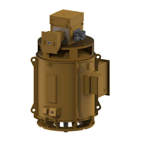
Low and high voltage three phase
induction motors
M line - Slip ring rotor
Vertical Liftable 2016
Installation, Operation and Maintenance Manual
Table of
Contents
Previous
Page
Next
Page
1
2
3
4
5
Advertisement
Table of Contents
Need help?
Do you have a question about the MAA and is the answer not in the manual?
Ask a question
Questions and answers
Related Manuals for WEG MAA
Engine WEG MAF Installation, Operation And Maintenance Manual
Low and high voltage three phase induction motors (59 pages)
Engine WEG MRX65-130 Assembly Instructions
Oor coupling rotary handle (nema 4x/ip65) (2 pages)
Engine WEG M line Series Installation, Operation And Maintenance Manual
Low and high voltage three phase induction motors (59 pages)
Engine WEG MAP Installation, Operation And Maintenance Manual
Low and high voltage three phase induction motors, m line slip ring rotor vertical liftable 2016 (71 pages)
Engine WEG MAT Installation, Operation And Maintenance Manual
Low and high voltage three phase induction motors, m line slip ring rotor vertical liftable 2016 (71 pages)
Engine WEG MAR Installation, Operation And Maintenance Manual
Low and high voltage three phase induction motors, m line slip ring rotor vertical liftable 2016 (71 pages)
Engine WEG M4 Manual For Installation, Operation And Maintenance
Low voltage eletric motors (2 pages)
Engine WEG W22 Premium Installation, Operation And Maintenance Manual
(111 pages)
Engine WEG W21 Instructions Manual For Installation, Operation And Maintenance
W22x series; w50x series. electric motors for explosive atmospheres (2 pages)
Engine WEG W21 Instruction Manual
Electric motors for explosive atmospheres (7 pages)
Engine WEG GPW Series Installation, Operation And Maintenance Manual
Synchronous alternators (39 pages)
Engine WEG W22Xdb Installation, Operation And Maintenance Manual
Flameproof motors (68 pages)
Engine WEG WGM Installation, Operation And Maintanance Manual
Three phase induction motors cooled by water jacket (55 pages)
Engine WEG W22Xd Instructions Manual For Installation, Operation And Maintenance
Electric motors for explosive atmospheres. w21 series; w22x series; w50x series; hgf series; ex61g series (40 pages)
Engine WEG W60 line Installation, Operation And Maintenance Manual
Three phase induction motors used in explosive atmospheres (low and high voltage) (63 pages)
Engine WEG WECM Installation, Operation And Maintenance Manual
Three-phase motors (25 pages)
This manual is also suitable for:
Map
Mad
Mat
Mav
Maf
Mar
...
Show all
Mai
Maw
Mal
Table of Contents
Print
Rename the bookmark
Delete bookmark?
Delete from my manuals?
Login
Sign In
OR
Sign in with Facebook
Sign in with Google
Upload manual
Upload from disk
Upload from URL


Need help?
Do you have a question about the MAA and is the answer not in the manual?
Questions and answers