Sign In
Upload
Manuals
Brands
WEG Manuals
Engine
MAP
WEG MAP Manuals
Manuals and User Guides for WEG MAP. We have
1
WEG MAP manual available for free PDF download: Installation, Operation And Maintenance Manual
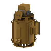
WEG MAP Installation, Operation And Maintenance Manual (71 pages)
Low and high voltage three phase induction motors, M line Slip ring rotor Vertical Liftable 2016
Brand:
WEG
| Category:
Engine
| Size: 2 MB
Table of Contents
Dear Customer
5
Table of Contents
7
Introduction
11
Safety Warnings in the Manual
11
General Instructions
12
Qualified Personnel
12
Safety Instructions
12
Standards
12
Environmental Conditions
12
Operating Conditions
13
Voltage and Frequency
13
Receiving, Handling and Storage
14
Receiving
14
Handling
14
Motor Positioning
14
Storage
15
Outdoor Storage
15
Extended Storage
15
Storage Location
15
Indoor Storage
15
Outdoor Storage
16
Separate Parts
16
Preservation During the Storage
16
Space Heater
16
Insulation Resistance
16
Exposed Machined Surfaces
16
Sealing
16
Bearings
16
Grease-Lubricated Rolling Bearing
16
Oil-Lubricated Rolling Bearing
16
Sleeve Bearing
17
Brushes
17
Terminal Boxes
17
Air-Water Heat Exchanger
17
Cleanliness and Conservation of the Motor During Storage
18
Inspections and Records During Storage
18
Predictive / Preventive Maintenance
18
Maintenance Plan During Storage
19
Preparation for Commissioning
20
Cleaning
20
Bearing Inspection
20
Bearing Lubrication
20
Brushes, Brush Holders and Slip Rings
20
Insulation Resistance Verification
20
Air-Water Heat Exchanger
20
Others
20
Installation
21
Installation Site
21
Shaft Lock
21
Axial Lock
21
Radial Lock
21
Procedure for Replacing the Radial Locking Device
21
Rotation Direction
21
Insulation Resistance
21
Safety Instructions
21
General Considerations
22
Measurement on the Stator Windings
22
Measurement on the Rotor Winding
22
Conversion of the Measured Values
22
Polarization Index
23
Recommended Minimum Values
23
Protections
23
Thermal Protections
23
Temperature Limits for the Windings
23
Alarm and Trip Temperatures
23
Temperature and Ohmic Resistance of the PT100 Thermoresistance
24
Space Heater
24
Water Leak Sensor
24
Cooling
24
Air-Water Heat Exchange Cooling
24
Radiators for Application with Seawater
25
Independent Ventilation Cooling
25
Electrical Aspects
25
Electrical Connections
25
Main Electrical Connections
25
Grounding
25
Connection Diagrams
26
Connection Diagrams According to IEC60034-8
26
Stator Connection Diagrams
26
Rotor Connection Diagrams
26
Connection Diagrams According to NEMA MG1
27
Stator Connection Diagrams
27
Rotor Connection Diagrams
27
Rotation Direction
27
Accessory Connection Diagrams
27
Motorized Brush Holder Connection Diagram
28
Condition for Starting with Lowered Brushes and Non-Short-Circuited Slip Rings
28
Condition for Operation with Lifted Brushes and Short-Circuited Slip Rings
29
Motorized Brush Holder Operation Logic
30
Manual Operation
30
Wiring Diagram of Motorized Brush Holder Control System
30
Mechanical Aspects
30
Base
30
Base Loads
30
Motor Mounting
30
Motor with Solid Shaft and Flange
31
Motor with Hollow Shaft and Flange
31
Anchor Plate Set
31
Natural Frequency of the Base
31
Leveling
31
Alignment
31
Hollow Shaft Motor Alignment
32
Doweling
33
Couplings
33
Direct Coupling
33
Gear Coupling
33
Belt Drive
33
Coupling for Hollow Shaft Motors
34
Hydraulic Unit
34
Liftable Brush Holder System
34
System Controller
34
Control System Automation Logic
35
Motor Starting Logic Interlock
35
Motor Operation Logic Interlock
35
System Fault Indicators
35
Liftable Brush Holder Operation Modes
35
Remote Motorized Mode
35
Local Motorized Mode
35
Manual Mode
36
Starting
37
Starting with Rheostat
37
Starting of Motors with Motorized Brush Holder
37
Conditions for Motor Starting
37
After Starting
37
Manual Operation
38
Commissioning
39
Preliminary Inspection
39
Commissioning of the Brushes Lifting System
39
Initial Checks
39
Manual Mode Activation
39
Local Motorized Mode Activation
40
Remote Motorized Mode Activation
40
Commissioning of the Control System Connected to the User System
41
Initial Checks
41
Motor Starting Simulation
41
Motor Shutdown Simulation
41
Characteristics of the Liftable Brush Holder Control System
41
Timers Setting
42
Operation
42
General
42
Load Condition
42
Temperatures
42
Bearings
42
High-Pressure Oil Injection System
42
Radiators
42
Vibration
43
Shaft Vibration Limits
43
Shutdown
43
Motor Starting and Shutdown
44
Preparation for Motor Starting
44
Motor Starting
44
Motor Shutdown
45
Maintenance
46
General
46
Brushes and Slip Rings
46
General Cleaning
46
Brushes Compartment Cleaning
46
Winding Maintenance
46
Winding Inspection
46
Winding Cleaning
46
Inspections
47
Reimpregnation
47
Insulation Resistance
47
Cooling System Maintenance
47
Radiator Maintenance
47
Vibration
47
Anti-Reversion Ratchet Maintenance
47
Slip Rings
47
Brush Holder and Brushes
48
Adjustment of the Brushes to the Load Conditions
48
Shaft Grounding Device
49
Bearing Maintenance
49
Grease-Lubricated Rolling Bearings
49
Instructions for Lubrication
49
Procedures for Rolling Bearing Relubrication
49
Rolling Bearing Relubrication with Drawer Device for Grease Removal
49
Type and Amount of Grease
50
Alternative Greases
50
Procedure for Changing the Grease
50
Low Temperature Greases
51
Grease Compatibility
51
Disassembly - Vertical Bearings
51
Before Disassembling
51
Lower Bearing Disassembly
51
Upper Bearing Disassembly
51
Bearing Assembly
52
Oil-Lubricated Rolling Bearing
52
Lubrication Instructions
52
Oil Type
52
Oil Change
52
Bearing Operation
53
Bearing Disassembly
53
Bearing Assembly
53
Rolling Bearing Replacement
54
Sleeve Bearings
54
Bearing Data
54
Bearing Installation and Operation
54
Cooling by Water Circulation
54
Oil Change
54
Sealing
55
Sleeve Bearing Operation
55
Sleeve Bearing Maintenance
55
Bearing Disassembly and Assembly
55
Thrust Bearing (Upper)
55
Guide Bearing (Lower)
56
Bearing Protection
56
Protection Settings
56
Disassembly/Assembly of the Sleeve Bearing Temperature Sensors
56
Maintenance of the Brush Lifting System
57
Preventive Maintenance Procedures
57
Inductive Sensors of the Liftable Brush Holder
57
Slip Rings Short-Circuit Contacts
58
Fixing the Drive Arm of the Short-Circuit Bushing
58
Gear Motor Maintenance
58
Motor Disassembly and Assembly
59
Parts List
59
Disassembly
59
Assembly
59
Air-Gap Measurement
59
Tightening Torque
60
Spare Parts
61
Maintenance Plan
62
Abnormalities, Causes and Solutions
63
Declaration of Conformity
66
Environmental Information
67
Package
67
Product
67
Hazardous Waste
67
Service Network
67
Warranty Term
68
Advertisement
Advertisement
Related Products
WEG MAA
WEG MAD
WEG MAT
WEG MAV
WEG MAF
WEG MAR
WEG MAI
WEG MAW
WEG MAL
WEG MGR
WEG Categories
DC Drives
Controller
Circuit breakers
Control Unit
Inverter
More WEG Manuals
Login
Sign In
OR
Sign in with Facebook
Sign in with Google
Upload manual
Upload from disk
Upload from URL