
Related Manuals for Unico S1100RS Series


Summary of Contents for Unico S1100RS Series
- Page 1 S1100RS Series Spectrophotometer Operation Manual United Products & Instruments, Inc. Dayton, NJ USA www.unicosci.com info@unicosci.com (732)274‐1155 ...
-
Page 2: General Information
SAFETY This spectrophotometer has been designed and tested in accordance with EN 61326‐1: 1997 Safety Requirements for Electrical Equipment for Measurement, Control, and Laboratory Use standard (EMC Requirements). The spectrophotometer has been tested and supplied in a safe condition. Read the following before installing and using the instrument and its accessories. ELECTRICAL The power plug shall be inserted in a socket provided with a protective grounded contact. The protective action must not be negated by the use of an extension cord without a protective conductor. Any interruption of the protective conductor inside or outside the spectrophotometer or disconnection of the protective ground terminal may make the spectrophotometer unsafe to use. Whenever it is likely that the protection has been impaired, the spectrophotometer shall be made inoperative and be secured against any unintended operation. The protection is likely to be impaired if, for example, the spectrophotometer • Shows visible damage • Fails to perform the intended measurements • Has been subjected to prolonged storage under unfavorable conditions • Has been subjected to severe transport stresses PERFORMANCE Carry out performance checks with particular reference to wavelength and absorbance accuracy to ensure that the spectrophotometer is working within its specification, especially when making measurements of an important nature. Performance checks are detailed in this manual. INTERFERENCE For compliance with the EMC standards referred to in the EC Declaration of Conformity, it is ® necessary that only shielded cables supplied by UNICO are used when connecting the instrument to computers and accessories. ... -
Page 3: Working Principle
INTRODUCTION ® The UNICO 1100/1100RS Spectrophotometers are single beam, general purpose instruments ® designed to meet the needs of the conventional laboratory. UNICO 1100/1100RS are ideal for various applications in Clinical Chemistry, General Education and other fields. Featuring a digital display of photometric result, easy operation, and wavelength range of 335 ® nm~1000 nm, UNICO 1100/1100RS are ideal for measurements in the visible wavelength region of the electromagnetic spectrum. WORKING PRINCIPLE The spectrophotometer consists of five parts: 1) Light Source (Halogen Lamp) to supply the light; 2) A Monochromator to isolate the wavelength of interest and eliminate the unwanted second order radiation; 3) A Sample Compartment to accommodate the sample solution; 4) A Detector to receive and convert the transmitted light to an electrical signal; 5) A Digital Display to show absorbance or transmittance. Figure‐1 illustrates the relationship between these parts. 100%T Light Source Monochromator Sample Compartment Detector Digital Display Figure‐1 Block Diagram for the Spectrophotometer In the spectrophotometer, light from the Halogen Lamp is focused on the entrance slit of the Monochromator where the collimating mirror directs the beam onto the grating. The grating disperses the light beam to produce the spectrum, a portion of which is focused on the exit slit of the Monochromator by a collimating mirror. From here the beam is passed to a Sample Compartment through one of the filters, which helps to eliminate unwanted second order radiation from the diffraction grating. Upon leaving the Sample Compartment, the beam is passed to the silicon photodiode Detector and causes the Detector to produce an electrical signal that is shown on the Digital Display window. SPECIFICATIONS ... -
Page 4: Installation
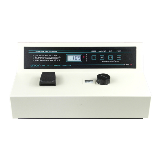
1 Power Cord 1 Cuvette (round) 12 Square Cuvette Adapter 1 Dust Cover 1 Operation Manual 1 INSTALLATION 1. Place the instrument in a suitable location and keep it as far as possible from any strong magnetic or electrical fields or any electrical device that may generate high‐frequency fields. Set the unit up in an area that is free of dust, corrosive gases and strong vibrations. ® 2. Turn on your UNICO 1100/1100RS and allow it to warm up for 15 minutes 1100RS SPECTROPHOTOMETER OPERATION PANEL MODE INDICATOR: Show the current measurement mode (T‐‐%Transmittance, A‐‐Absorbance, C‐‐ Concentration, and F‐‐Factor) (refer to Figure‐4). : There are four modes. T mode is transmittance mode; A mode is absorbance MODE BUTTON... -
Page 5: Changing Sample Holders
∧ (0A/100%T) BUTTON: Set spectrophotometer to 100%T or 0.000A when the reference solution is in the Sample Compartment. ∨ (0%T) BUTTON: in T mode and the Sample Compartment is empty, internal shutter blocks the beam. Press to set the Digital Display reading to 00.0%T. ENT (PRINT) Button: in A and %T modes will send the displayed results to printer; in C mode, set the concentration value (refer to Concentration Mode in Additional Features of Model 1100RS section); in F mode, set the factor number and change to C mode (refer to Factor Mode in Additional Features of Model 1100RS section); If you want to print the test results at C mode, push the MODE button to the position when the LED light is off, then push the ENT button SAMPLE COMPARTMENT: Accept 10 mm test tube or 10 mm square cuvette (the square cuvette adapter is required). WAVELENGTH KNOB: Select desired wavelength in nanometers (nm). WAVELENGTH READOUT Window: Display desired wavelength. CHANGING SAMPLE HOLDERS S‐1100RS comes standard with the S‐1100‐102 Sample Holder. UNICO offers three additional holders as optional accessories, please refer to Table‐2 “1100 and 1100RS Parts List” in 1100 and 1100RS Parts List of this manual. To change the Cuvette Sample Holder: • Open the lid of the Sample Holder, and locate the Sample Holder Locking Screw • Use Allen Wrench (S‐1100‐521) to loosen the Screw counterclockwise • Remove the Sample Holder you want to change, insert the one you want to install, align it properly, and fasten the Screw Screw Allen Wrench ... -
Page 6: Basic Operation
BASIC OPERATION ® OPERATION INSTRUCTIONS are printed on the front panel of your UNICO 1100/1100RS. Sample Preparation and Analysis A. Spectrophotometer Warm‐up 1. Turn on the spectrophotometer by turning on the Power Switch (IO). Allow 15 minutes for the instrument to warm up. 2. Select either the T (Transmittance Mode) or A (Absorbance Mode) by pressing the MODE button until the red light for T or A is on. Select the desired wavelength by turning the WAVELENGTH control knob. Sample Preparation Make a blank reference solution by filling a clean square cuvette (or test tube) half full with distilled/de‐ionized water or other specified solvent. Wipe the cuvette with tissue to remove the fingerprints or droplets of liquid. Insert the blank square cuvette into the square cuvette adapter and place the adapter in the Sample Compartment (if using test tube, insert it directly into the Sample Compartment, aligning the guide mark (if present) with the guide mark at the front of the Sample Compartment). Close the lid. Set 0.000A or 100%T with the 0A/100%T (∧) button. NOTE: This step fulfills the instruction on the front of the spectrophotometer Remove the blank square cuvette or test tube. Set it aside in case that you may need to adjust the 0A/100%T using 0A/100%T (∧) button later (i.e. change the wavelength). Sample Analysis 8. Rinse a second square cuvette with a small amount of the sample solution to be tested. Fill the square cuvette half full and wipe clean the exterior of the cuvette. ... -
Page 7: Factor Mode
Concentration is known to be linear. The concentration of the Standard solution used to calibrate the instrument should be higher than the most concentrated sample. 1. Select the desired wavelength by turning the wavelength control knob. 2. Using the MODE button, select A mode. 3. Insert the cuvette containing the blank solution. 4. Set 0.000A with the ∧ button. 5. Using the MODE button, select C mode. 6. Insert a cuvette containing a standard solution of known concentration in the Sample Compartment and set the Digital Display window to be the value of the standard by using the ∧ and ∨ buttons. 7. Press the ENT button. NOTE: If the reading changes, the factor required is too high (i.e. >1999) to be displayed. In this case, divide the concentration by 10; re‐select the C mode by successive presses on the MODE button, cycling through the F, T, and A modes, and follow step 2 above to set the concentration of the standard to the reduced value. Push the MODE button till the Mode Indicator light is off, then push ENT button; you can print the test result under C Mode. 8. With the standard concentration set, determine the concentration values of samples with unknown concentration by inserting the sample cuvette into the Sample Compartment and reading the value direct from the Digital Display. 9. To read the value of the multiplier used to convert Abs to Concentration, after measuring all the samples, change the mode to F and read the multiplier from the display. Keep a record of this value for future use. Operational Note: if the MODE is changed to read F or A, the Concentration C reading is “frozen, re‐start at step 1. FACTOR MODE This is a special mode for measuring concentration values of unknown samples using a previously determined factor to convert absorbance readings to concentration. 1. -
Page 8: Maintenance
Remove the grill plate on bottom of the instrument by removing the fixing screw. Unplug the lamp from the white connector. Insert the new lamp; pushing it in as far as it will go. Replacement lamp Item Number: S‐1100‐505 (6V 10W G4 type) CAUTION: DO NOT HANDLE THE LAMP WITH BARE FINGERS. USE TISSUE OR CLOTH WHEN HANDLING LAMP. 3. Turn on the instrument. Set the wavelength at 340 nm, insert a test tube or an empty cuvette with cuvette adapter, and blank the instrument. If the energy is low, adjust the lamp by “pulling” or “pushing” it so that the light beam is focused on the entrance slot of the monochromator. Since the lamp socket is pre‐aligned, there will be minimum, if any, adjustment required. 4. Re‐install the grill plate. Wavelength Calibration Check ® Normally the UNICO 1100 Series spectrophotometer retains its wavelength calibration indefinitely. However if the instrument receives a severe shock or is abused, use the following methods to check wavelength calibration. In the filter method, the didymium filter has two distinct absorbance peaks at 529 nm and 807 nm. The Holmium filter has a distinct peak at 361 nm. When the instrument is calibrated properly you will find minimum Transmittance (maximum Absorbance) at the range ± 2 nm from these peaks. Note that the specific Transmittance values are not important as you are only looking for the wavelength where the minimum Transmittance (maximum Absorbance) occurs. Note: If you calibration filter has a certified peak/valley curve attached, please use the peaks on the curve to verify the instrument. Holmium Oxide Filter Method 1. Turn instrument on and allow it to warm up for 15 minutes. 2. Select the A mode. 3. Set the wavelength to 350 nm. ... -
Page 9: Didymium Filter Method
9. If a “middle” wavelength check is desired, set the wavelength to 522 nm (optional) 10. Make sure the cuvette adapter is empty, place it in the Sample Compartment. Close the lid. 11. Set zero Abs by pressing the 0A/100%T (∧) button. Wait a few seconds when the display flashes. The reading should then be 0.000A. If not repeat step 11. 12. Remove the cuvette adapter and insert the Didymium filter into it. Place it in the Sample Compartment again and close the lid. 13. Record the absorbance reading on the Digital Display window. 14. Advance the wavelength setting by 1 nm and repeat step 10 to 13. 15. Repeat step 14 until the wavelength setting reaches 536 nm. Again, look for the maximum absorbance reading. It should be within 527~531 nm. ABSORBANCE ACCURACY CHECK Specification: ± 2% at 1A (1100), ± 1% at 1A and 2A (1100RS). The absorbance accuracy should be checked against a set of neutral density filters accurately ® calibrated to the NIST standards. Contact your UNICO representative for more information. An alternative method using potassium dichromate is described below. Due to the many factors that might affect the results (i.e. temperature, bandpass, weighing and diluting errors), this method is less accurate and should only be used as a guide. Reference: Johnson E A Potassium Dichromate as an absorbance standard; PSG Bulletin 1967, No. 17, page 505 Make up N/100 sulfuric acid as the solvent and use part of it to make a solution containing 120 + 0.5 mg/l of potassium dichromate. Wash out a square cuvette with solvent, and fill with solvent. Put the cuvette in the cuvette adapter, then into the Sample Compartment and close the lid. Set the wavelength to 350 nm. Set the MODE button to A. Set the reading to 0.000A using the 0A/100%T (∧) button. Empty the cuvette. Wash out with dichromate solution, and fill with dichromate solution. ... -
Page 10: Stray Light Check
Set the wavelength to 340 nm, set the MODE button to T. With the square cuvette adapter in the Sample Compartment, but no cuvette, close the lid and press the 0A/100%T (∧) button to set the display to 100.0%. Remove the cuvette adapter from the Sample Compartment and close the lid. Make a note of the reading that should be at or near 0.00. Prepare a 5% (50g/L) solution of sodium nitrite (NaNO ) in distilled water and fill a square cuvette with this solution. 6. Insert the cuvette into the cuvette adapter, place it in the Sample Compartment, and close the lid. The display should read < 0.5%T. If the reading obtained in step 4 is greater than 0.00, it should be subtracted from the displayed reading to give the correct reading for the stray light value. 1100 and 1100RS PARTS LIST Item Number Description ® S‐1100 UNICO Model 1100 Spectrophotometer 20 nm Bandpass Wavelength range: 335~1000 nm. Voltage preset at 110V Complete with 10 mm Test Tube Cuvettes (12 pcs.) 10 mm Cuvette Adapter, Dust Cover, User Manual ® S‐1100RS UNICO Model 1100RS Spectrophotometer 10 nm Bandpass Wavelength range: 335~1000 nm. Voltage preset at 110V Complete with 10 mm Test Tube Cuvettes (12pcs.) 10 mm Cuvette Adapter, RS‐232C Port, Dust Cover, User Manual ® S‐1100‐401 UNICO Software for Window's. Programs include Standard Curve, Abs./%T/Conc., and Abs.vs.Time. Accessories S‐1100‐102 Test Tube Sample Holder for 10 mm diameter Test Tubes ... -
Page 11: Troubleshooting
S‐1100‐521 Allen Wrench TROUBLESHOOTING PROBLEM Possible Cause Solution Instrument Power cord not connected to outlet Plug instrument in Inoperative Dead Power outlet Change to a different outlet (Power indicator Wrong voltage setting has no light) Internal fuse blown or defective electronic Call an authorized service component engineer Instrument can No Cuvette Adapter in the Sample Cuvette Adapter must be in not set 100%T Compartment Sample Compartment to (0.000A) open sample holder shutter Light beam blocked: Check sample holder • Holder misaligned • Shutter Lamp is old or defective ... - Page 12 and noise Significant temperature change properly installed or has Lamp not adjusted properly moved during transit Refer to Lamp Replacement instructions in this manual Lamp old or defective Replace with a new lamp Sample Holder Misaligned Refer to Lamp Replacement instructions in this manual Unstable power supply Call an authorized service Defective or dirty detector or defective engineer electronic component Incorrect readings Insufficient sample volume Fill cuvette with more sample obtained Wrong wavelength setting Check analytical procedure Failed to blank (0A/100%T) and wavelength setting Failed to set 0%T Check wavelength accuracy according to procedure in this manual Stray sample preparation vapors Prepare sample away from instrument. Use proper ventilation Bubbles or particles in solution Check sample preparation and analytical procedure Instrument out of electronic calibration Call an authorized service engineer ...
Need help?
Do you have a question about the S1100RS Series and is the answer not in the manual?
Questions and answers