Sign In
Upload
Download
Table of Contents
Contents
Add to my manuals
Delete from my manuals
Share
URL of this page:
HTML Link:
Bookmark this page
Add
Manual will be automatically added to "My Manuals"
Print this page
×
Bookmark added
×
Added to my manuals
Manuals
Brands
Unico Manuals
Measuring Instruments
SQ Series
Service manual
Unico SQ Series Service Manual
Spectrophotometer
Hide thumbs
1
Table Of Contents
2
3
4
5
6
7
8
9
10
11
12
13
14
15
16
17
18
19
20
21
22
23
24
25
26
27
28
29
30
31
32
33
34
35
36
37
38
39
40
41
42
43
44
45
46
47
48
49
50
51
52
53
54
55
56
57
58
59
60
61
62
63
64
65
66
67
68
69
70
71
72
73
74
75
76
77
78
79
80
81
82
83
84
85
86
87
88
89
90
91
92
93
94
95
96
page
of
96
Go
/
96
Contents
Table of Contents
Troubleshooting
Bookmarks
Table of Contents
Table of Contents
Introduction
Specifications
Layout
Layout of UV-2800
Layout of UV-2802(S),UV-2802PC(S)
Layout of UV-3802
Layout of UV-4802
Optical System
Incidence of Light
Dispersion of Light
Exit of Light
Exit of the Single Beam(UV-2800, UV-2802, UV-2802S)
Exit of the Split Beam(UV-3802)
Exit of the Double Beam(UV-4802)
Electronic System
Power Supply System
Power Supply PCB
Power Distributing PCB
Control and Drive System
Main CPU PCB
Drive PCB
Transferring PCB
Sampling and Signal Processing System
Amplifier PCB
Slave Amplifier PCB
Slave CPU PCB
Trouble Shooting
Tungsten Lamp off
Deuterium Lamp off
Memory Check Failed
Printer Check Failed
Filter Positioning Failed
Light Source Positioning Failed
Search 656.1Nm Failed
Please Restart" Warning
Battery Low" Warning
Save or Load File Failed
Get Dark Current for a Long Time
No Backlight on LCD Display
Energy Low" Warning after Blanking
Energy too Low" Warning
No DC +12V on PCB SST8.412.113
Maintenance
Working Environment
Replace Tungsten Lamp
Replace Deuterium Lamp
Replace Memory Battery
Upgrade Firmware
Check Performance
Prepare
Check Wavelength Accuracy
Check Stray Light
Check Absorbance Accuracy
Check Dark Current
Check Energy Profile
Appendix
Order NO. List of UV-2800
Order NO. List of UV-2802, UV-2802PC
Order NO. List of UV-2802S, UV-2802PCS
Order NO. List of UV-3802
Order NO. List of UV-4802
Advertisement
Quick Links
1
Table of Contents
2
Specifications
3
Layout of Uv-2800
4
Trouble Shooting
Download this manual
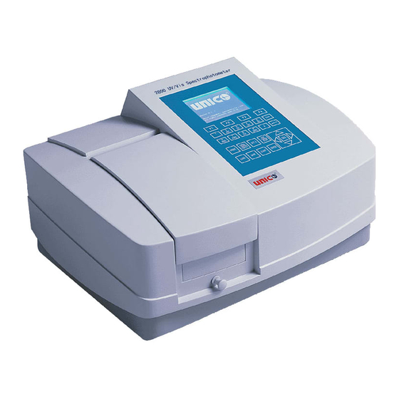
UNICO SQ Series
MODEL
UV-2800 / UV-2802 /UV-2802PC/UV-2802S/
UV-2802PCS / UV-3802 / UV-4802
SPECTROPHOTOMETER
SERVICE MANUAL
UNICO
182 Ridge Road, Suite E Dayton, NJ 08810 USA
732-274-1155 Fax: 732-274-1151 WEB:
www.unicosci.com
E-mail: Sales@unicosci.com
Table of
Contents
Previous
Page
Next
Page
1
2
3
4
5
Advertisement
Table of Contents
Need help?
Do you have a question about the SQ Series and is the answer not in the manual?
Ask a question
Questions and answers
Related Manuals for Unico SQ Series
Measuring Instruments Unico UV-2802 User Manual
Single beam scanning uv/visible spectrophotometer (56 pages)
Measuring Instruments Unico S1205 SERIES User Manual
Spectrophotometer (27 pages)
Measuring Instruments Unico S-2150 Series User Manual
(44 pages)
Measuring Instruments Unico S-1100 Operation Manual
(10 pages)
Measuring Instruments Unico S1100RS Series Operation Manual
(13 pages)
Measuring Instruments Unico 1200 Series User Manual
(13 pages)
Measuring Instruments Unico 2100 Series User Manual
(33 pages)
This manual is also suitable for:
Uv-2800
Uv-2802
Uv-2802pc
Uv-2802s
Uv-2802pcs
Uv-3802
...
Show all
Uv-4802
Table of Contents
Save PDF
Print
Rename the bookmark
Delete bookmark?
Delete from my manuals?
Login
Sign In
OR
Sign in with Facebook
Sign in with Google
Upload manual
Upload from disk
Upload from URL


Need help?
Do you have a question about the SQ Series and is the answer not in the manual?
Questions and answers