Table of Contents
Advertisement
Quick Links
Advertisement
Table of Contents

Subscribe to Our Youtube Channel
Related Manuals for Gentec-EO UP16K-30H-QED-D0


Summary of Contents for Gentec-EO UP16K-30H-QED-D0
-
Page 2: Warranty
All Gentec-EO products carry a one-year warranty from the date of shipment on material or workmanship defects when used under normal operating conditions. Gentec-EO will repair or replace, at its sole discretion, any product that proves to be defective during the warranty period. -
Page 3: Safety Information
Revision 3.7 SAFETY INFORMATION Do not use a Gentec-EO device if the monitor or the detector looks damaged or if you suspect that the device is not operating properly. Appropriate installation must be done for water-cooled and fan-cooled detectors. Refer to the specific instructions for more information. -
Page 4: Table Of Contents
INTEGRA user manual Revision 3.7 TABLE OF CONTENTS INTEGRA ..................................6 1.1. Introduction ................................. 6 1.2. Specifications ..............................6 1.2.1. DB-9 pinout ............................... 6 1.2.2. Range adjustment ............................6 Quick start procedure..............................7 User interface ................................8 USB and RS-232 serial communication ......................... 9 4.1. -
Page 5: Introduction
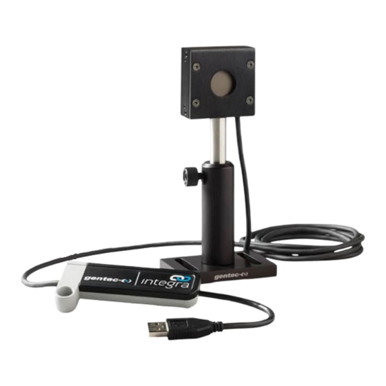
The small but powerful meter of the INTEGRA series presents a direct USB or RS-232 connection so you can plug it into your PC. Simply use the PC-Gentec-EO software supplied with your product and be ready to make power or energy measurements within seconds! Each detector of the INTEGRA series offers the same incredible performance as the usual detector and meter combination, from pW to kW and from fJ to J. -
Page 6: Integra
INTEGRA user manual Revision 3.8 Example for the external trigger timing requirements: • If the head detector has a risetime of Tresp = 20 µs, the time frame will be from (20% * 20 µs = 4 µs) before the laser pulse to (20 µs – 1 µs = 19 µs) after the laser pulse. •... -
Page 7: Quick Start Procedure
Energy detectors can only be used with pulsed lasers. Adjust the zero: The power read by PC-Gentec-EO when no laser beam is incident on the detector may not be exactly zero. For power measures, this is because the detector is not thermally stabilized OR there was a heat source in the field of view of the detector when you connected the PC-Gentec-EO. -
Page 8: User Interface
Do not adjust the zero for energy detectors, such as the QE series. iv. Avoid forced airflow or drafts around the detector. 3. USER INTERFACE Please refer to the PC-Gentec-EO manual for more information concerning the user interface. The manual can be downloaded on our website at: https://gentec-eo.com/downloads/specsheets-manuals. -
Page 9: Usb And Rs-232 Serial Communication
INTEGRA user manual Revision 3.8 4. USB AND RS-232 SERIAL COMMUNICATION 4.1. DESCRIPTION The INTEGRA has two communication modes: the binary mode for fast data acquisition and the ASCII mode. Both modes will require text input commands which must follow the rules stated in Section 0. The output can be in binary mode or in ASCII mode. -
Page 10: To Echo Commands
INTEGRA user manual Revision 3.8 RS-232 INTEGRA COM port settings Bits per second 115,200 Data bits Parity None Stop bits Flow control None 4.2.2. To echo commands The commands you type will not appear in the terminal window unless you set up the terminal emulator to do so. -
Page 11: Serial Command Format
4.4. BINARY MODE OUTPUT FORMAT 4.4.1. Description The INTEGRA’s resolution is 12 bits for the joulemeter mode. To be compatible with other Gentec-EO monitors, a 14-bit value is sent, but the two LSBs of the low byte are not significant. - Page 12 INTEGRA user manual Revision 3.8 Examples to decode binary commands Example 1: Using *CAU or *CVU INTEGRA is measuring 151 mJ in a 300 mJ scale. The data sent by INTEGRA will be: 0x40B4. Decode this as follows: 1. Look at bit 7 of each byte to determine the high and low bytes. 2.
- Page 13 INTEGRA user manual Revision 3.8 Examples to decode binary commands The pulse period bytes are 0x8080FABC. Mask off bit 7 of each byte resulting in 0x003D3C or 15,676 decimal. The period timer is based on a 24E6 Hz clock, so the period is found as: If you send *ceu, it will be 15,676 counts / 24E6 counts per second = 653.17us.
-
Page 14: List Of Serial Commands For The Integra (Summary)
INTEGRA user manual Revision 3.8 4.5. LIST OF SERIAL COMMANDS FOR THE INTEGRA (SUMMARY) Command name Command Description Display Set scale Manually sets the scale Set scale up Changes scale to the next higher scale Set scale down Changes scale to the next lower scale Get current scale index Returns scale index between 0 and 41 Set autoscale... - Page 15 INTEGRA user manual Revision 3.8 The serial command format is: All text commands must begin with a trig character (*) and MUST NOT end with a line feed or a carriage return. All parameters MUST NOT have a space between the command and the list of parameters, nor between the parameters themselves.
-
Page 16: Detailed Description Of The Serial Commands For Integra (Complete)
INTEGRA user manual Revision 3.8 4.6. DETAILED DESCRIPTION OF THE SERIAL COMMANDS FOR INTEGRA (COMPLETE) 4.6.1. Display 01 - Set scale This command is used to force the display of the current data into a specific scale. The lower scale is always zero, the higher scales can be found in the table below. - Page 17 INTEGRA user manual Revision 3.8 03 - Set scale down This command is used to force the display of the current data into a lower scale. Command Parameters Answer None 04 - Get current scale index This command returns the scale index between 0 and 41. Please refer to set scale command (SCS) details for the complete scale index table.
- Page 18 INTEGRA user manual Revision 3.8 07 - Display valid scale This command is used to display all of the valid scales the connected head supports. The scales are displayed in the scale index. Please refer to the set scale section for the table correspondence. Command Parameters Answer...
- Page 19 INTEGRA user manual Revision 3.8 09 - Get trigger level This command returns the trigger level in %. The value is between 0.1% and 99.9%. This is for joulemeters and wattmeters in energy mode only. Command Parameters Answer None Returns the trigger level in % Example Command: *GTL...
-
Page 20: Data Acquisition
INTEGRA user manual Revision 3.8 4.6.2. Data acquisition 11 - Query current value This command is used to query the value that is currently being displayed by the monitor. The value is displayed in watts or in joules. For joulemeters, the data can also be in binary format (refer to Section 4.4). Command Parameters Answer... - Page 21 INTEGRA user manual Revision 3.8 In the original series v1.00.XX, the joulemeters and photodiodes also use the scientific notation. For example, with a joulemeter, a reading of around 500 millijoules would be displayed as shown below until the command *CSU is sent. Command: *CAU Answer (original series...
- Page 22 INTEGRA user manual Revision 3.8 14 - Send current value with frequency INTEGRA will send the current measurement and the pulse repetition rate in Hz. They are comma-separated. This is for joulemeters only. For joulemeters, the data can also be in binary format (refer to Section 4.4). Command Parameters Answer...
- Page 23 INTEGRA user manual Revision 3.8 18 - Set binary joulemeter mode This command is used to set the monitor in binary or ASCII mode. Refer to Section 4.4 for the INTEGRA binary mode description. This is for joulemeters only. Command Parameters Answer 0= ASCII...
-
Page 24: Setup
INTEGRA user manual Revision 3.8 4.6.3. Setup 20 - Set personal wavelength correction in nm This command is used to specify the wavelength in nm being used on the detector. The EEPROM in the detector contains measured spectral data for a wide range of wavelengths. A valid value is set between the lowest and highest wavelengths supported by the device, and it should not be a floating point value. - Page 25 INTEGRA user manual Revision 3.8 21 - Set personal wavelength correction in microns This command is used to specify the wavelength in microns for THZ detectors only. The EEPROM in the detector contains measured spectral data for a wide range of wavelengths. A valid value is set between the lowest and highest wavelengths supported by the device.
-
Page 26: Control
INTEGRA user manual Revision 3.8 4.6.4. Control 23 - Set anticipation This command is used to enable or disable the anticipation processing when the device is reading from a wattmeter. The anticipation is a software-based acceleration algorithm that provides faster readings using the detector’s calibration. - Page 27 INTEGRA user manual Revision 3.8 25 - Noise suppression Sets or queries the sampling size of the noise suppression. For pyroelectric detectors and UM detectors only. The INTEGRA joulemeter instrument has a special proprietary algorithm that can lower the noise-induced error when reading low energy levels or energy readings of any level with noise present.
- Page 28 INTEGRA user manual Revision 3.8 27 - Clear zero offset This command undoes the zero offset command to set the zero point at zero. Command Parameters Answer None 28 - Get zero offset This command returns whether the zero offset has been activated or not. Command Parameters Answer...
- Page 29 INTEGRA user manual Revision 3.8 30 - Set user multiplier This command is used to set the value of the multipliers. Command Parameters Answer Eight-character numerical value Default: 1 Example The following example sets multiplier = 33. Command: *MUL00000033 Answer: *MUL3.3000e1 31 - Get user multiplier This command returns the multiplier value.
- Page 30 INTEGRA user manual Revision 3.8 33 - Get user offset This command returns the offset value. Command Parameters Answer None Current offset value Example Command: *GUO Answer: User Offset: 1.5000000E-03<CR><LF> 34 - Set single shot energy mode This command is used to toggle to single shot energy mode when using a wattmeter. It is recommended to wait at least 2 seconds after this command before sending another command to avoid communication problems.
-
Page 31: Instrument And Detector Information
INTEGRA user manual Revision 3.8 36 - Get attenuator This command returns the attenuator status. If the attenuator is not available, it will always be off. Command Parameters Answer None 1: On 0: Off Example Command: *GAT Answer: Attenuator: 0<CR><LF> 37 –... - Page 32 INTEGRA user manual Revision 3.8 39 - Query version This command is used to query the device to get information about the firmware version and the device type. Command Parameters Answer None Version and device type Example Command: *VER Answer: INTEGRA Version 1.00.00<CR><LF> 40 - Query status This command is used to query the device to get information about the following characteristics: •...
- Page 33 INTEGRA user manual Revision 3.8 Hexadecimal structure Converted value Definition Valid Address Value 0012 0001 Is Attenuator available LSB (1= yes 0 = no) 0013 0000 Is Attenuator available MSB (1= yes 0 = no) 0014 0000 Is Attenuator on LSB (1= yes 0 = no) 0015 0000 Is Attenuator on MSB (1= yes 0 = no)
- Page 34 INTEGRA user manual Revision 3.8 The following table shows the output with an XLP12-3S-H2-INT-D0 (s/n 199672). Note that text data values such as detector name and serial number are in ASCII-encoded little-endian 16-bit chunks. The byte order must be reversed to be converted into a readable format. Hexadecimal structure Converted value Definition...
-
Page 35: Error Messages
INTEGRA user manual Revision 3.8 Hexadecimal structure Converted value Definition Valid Address Value 002D 00 = Null termination character 002E 0000 Reserved 002F 0000 Reserved 0030 0001 Is autoscale mode on? LSB 0031 0000 Is autoscale mode on? MSB 0032 0000 Is anticipation on? LSB 0033... -
Page 36: Usb Driver Installation
6.1. FREE SOFTWARE UPGRADE Keep up to date with the latest versions of PC-Gentec-EO software to get the new features and options. As new and improved versions of the device firmware are created, it is in your best interest to update your INTEGRA. -
Page 37: Declaration Of Conformity
INTEGRA user manual Revision 3.8 7. DECLARATION OF CONFORMITY Application of Council directive(s): 2014/30/EU EMC Directive tests in compliance with FCC part 15 subpart B Manufacturer’s name: Gentec Electro Optics, Inc. Manufacturer’s address: 445, Saint-Jean-Baptiste, Suite 160 Québec (Québec) G2E 5N7 Canada Representative’s name: Laser Component S.A.S. - Page 38 INTEGRA user manual Revision 3.8 Test name Performance Test specifications Results Standards criterion Voltage dips: 0% during 1 cycle Voltage Dips, Short Interruptions and Voltage 40% during 10 cycles Variation Immunity on AC Input Pass 70% during 25 cycles IEC61000-4-11 (2004) Short interruptions: 0% during 250 cycles I, the undersigned, hereby declare that the equipment specified above...
-
Page 39: Ukca Declaration Of Conformity
INTEGRA user manual Revision 3.8 8. UKCA DECLARATION OF CONFORMITY Application of Council directive(s): 2014/30/EU EMC Directive tests in compliance with FCC part 15 subpart B Manufacturer’s name: Gentec Electro Optics, Inc. Manufacturer’s address: 445, rue Saint-Jean-Baptiste, Suite 160 Québec (Québec) G2E 5N7 Canada Representative’s name: Laser Component S.A.S. - Page 40 INTEGRA user manual Revision 3.8 Test name Performance Test specifications Results Standards criterion Voltage dips: 0% during 1 cycle Voltage Dips, Short Interruptions and Voltage 40% during 10 cycles Variation Immunity on AC Input Pass 70% during 25 cycles IEC61000-4-11 (2004) Short interruptions: 0% during 250 cycles I, the undersigned, hereby declare that the equipment specified above...
-
Page 41: Appendix A: Weee Directive
INTEGRA user manual Revision 3.8 9. APPENDIX A: WEEE DIRECTIVE Recycling and separation procedure for WEEE directive 2002/96/EC This section is used by the recycling centre when the monitor reaches its end of life. Breaking the calibration seal or opening the monitor will void the INTEGRA warranty. For the head, please refer to the head’s manual. The complete monitor contains: 1 monitor 1 USB cable... - Page 42 INTEGRA user manual Revision 3.8...
Need help?
Do you have a question about the UP16K-30H-QED-D0 and is the answer not in the manual?
Questions and answers