Table of Contents
Advertisement
Quick Links
Advertisement
Table of Contents

Subscribe to Our Youtube Channel
Related Manuals for Gentec-EO INTEGRA Series


Summary of Contents for Gentec-EO INTEGRA Series
- Page 2 Gentec-EO agent. Gentec-EO Inc. assumes no risk for damage during transit. Gentec-EO Inc. will, at its option, repair or replace the defective product free of charge or refund your purchase price. However, if Gentec-EO Inc. determines that the failure is caused by misuse, alterations, accident or abnormal conditions of operation or handling, it would therefore not be covered by the warranty.
- Page 3 INTEGRA User Manual Revision 1.1 SAFETY INFORMATION Do not use a Gentec-EO device, if the monitor or the detector looks damaged, or if you suspect that the device is not operating properly. Appropriate installation must be done for water-cooled and fan-cooled detectors.
-
Page 4: Table Of Contents
INTEGRA User Manual Revision 1.1 TABLE OF CONTENTS INTEGRA ......................... 1 1.1. Introduction ..............................1 1.2. Specifications .............................1 Quick Start Procedure ....................3 User Interface ......................... 4 USB Serial Communication ..................4 4.1. Description ..............................4 4.2. Setting up Communication to the INTEGRA ....................4 4.2.1. - Page 5 INTEGRA User Manual Revision 1.1 30 - Get User Multiplier ..............................18 31 - Set User Offset ..............................18 32 - Get User Offset ..............................19 33 - Set Single Shot Energy Mode ..........................19 34 - Set Attenuator ............................... 19 35 - Get Attenuator ...............................
-
Page 6: Integra
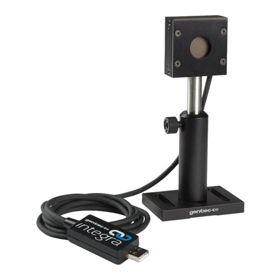
The INTEGRA is a series of All-in-One detectors that combine a detector and a meter in one convenient product. The small but powerful meter of the INTEGRA Series presents a direct USB connection so you can plug it into your PC. Simply use the PC-Gentec-EO software supplied with your product and be ready to make power or energy measurements within seconds! Each detector of the INTEGRA Series offers the same incredible performance as the usual detector and meter combination, from pW to kW and from fJ to J. - Page 7 INTEGRA User Manual Revision 1.1 1.1. OUTLINE DRAWING...
-
Page 8: Quick Start Procedure
Energy detectors can only be used with pulsed lasers. Adjust the Zero: The power read by PC-Gentec-EO when no laser beam is incident on the detector may not be exactly zero. For power measures, this is because the detector is not thermally stabilized OR there was a heat source in the field of view of the detector when you connected the PC-Gentec-EO. -
Page 9: User Interface
Do not adjust the zero for energy detectors, such as the QE series. iv. Avoid forced airflow or drafts around the detector. USER INTERFACE Please refer to the PC-Gentec-EO manual for more information concerning the user interface. The manual can be downloaded on our website at https://gentec-eo.com/downloads/specsheets-manuals. USB SERIAL COMMUNICATION 4.1. -
Page 10: To Echo Commands
INTEGRA User Manual Revision 1.1 Select: Start → Programs → Accessories → Communications → HyperTerminal To save communication settings, enter a name for the connection. n the drop down menu for “Connect using” select the COM port that the USB driver was installed on (Section 4.2.1). Select OK. Input the following settings into the communications parameter window that appears next. -
Page 11: Binary Mode Output Format
INTEGRA User Manual Revision 1.1 In case of an error, the reply string is in the following format: Error X: reason [enter] Where X is the error code, and reason is an explanation. See Error Codes at the end of this section. - Page 12 INTEGRA User Manual Revision 1.1 How to Use Binary Commands Example 1: Out of Scale Condition when Using *CEU or *CTU If the value of these bytes is 0xFE7F, an out of scale condition exists. INTEGRA is measuring 151 mJ in a 30 0mJ scale. The data sent by INTEGRA will be: 0x40B6 Decode this as follows.
-
Page 13: List Of Serial Commands For The Integra (Summary)
INTEGRA User Manual Revision 1.1 4.5. LIST OF SERIAL COMMANDS FOR THE INTEGRA (SUMMARY) Command Name Command Description DISPLAY Set Scale Manually sets the scale Set Scale Up Changes scale to the next higher scale Set Scale Down Changes scale to the next lower scale Get Current Scale Index Returns scale index between 0 and 41 Set Autoscale... -
Page 14: List Of Serial Commands For The Integra (Complete)
INTEGRA User Manual Revision 1.1 The Serial Commands Format is: All text commands must begin with a trig character (*) and DO NOT end with a line-feed or a carriage-return. All parameters must NOT have a space between the command and the list of parameters, nor between the parameters themselves. -
Page 15: Set Scale Up
INTEGRA User Manual Revision 1.1 Example The following example sets the scale to 3 nanowatts or nanojoules: Command: *SCS08 Answer: 02 - Set Scale Up This command is used to force the display of the current data into a higher scale. Command Parameters Answer... -
Page 16: Get Autoscale
INTEGRA User Manual Revision 1.1 06 - Get Autoscale This command returns whether or not the autoscale option is activated. Command Parameters Answer None 1: On 0: Off Example Command: *GAS Answer: Autoscale : 1 \r\n 07 - Display Valid Scale This command is used to display all of the valid scales the connected head supports. -
Page 17: Get Trigger Level
INTEGRA User Manual Revision 1.1 Example Command: *STL15.4 (15.4%) Answer: *STL0.20 (.2%) 09 - Get Trigger Level This command returns the trigger level in %. The value is between 0.1% and 99.9%. Command Parameters Answer None Returns the trigger level in %. Example Command: *GTL Answer:... -
Page 18: Send Continuous Transmission Of Data
INTEGRA User Manual Revision 1.1 Example For example, a 12 milliwatts reading would be displayed like this: Command: *CVU Answer: 0.012 <CR> <LF> 12 - Send Continuous Transmission of Data This command is used to send data to the serial port according to the data sampling setting. The maximum transfer speed is 200 Hz. -
Page 19: Stop The Cau Command
INTEGRA User Manual Revision 1.1 15 - Stop the CAU Command This command is used to stop the real time transfer enabled by the CAU Command. Command Parameters Answer None 16 - Query New Value Ready This command is used to check whether a new value is available from the device. Though optional, its use is recommended when doing single pulse operations. -
Page 20: Set Binary Joulemeter Mode
INTEGRA User Manual Revision 1.1 18 - Set Binary Joulemeter Mode This command is used to set the monitor in binary or ASCII mode. Refer to section 4.4 for the INTEGRA binary mode description. Command Parameters Answer 0= ASCII 1= Binary Example Answer: The INTEGRA is set in binary... -
Page 21: Get Wavelength
INTEGRA User Manual Revision 1.1 Example The following example sets the wavelength to 1550 nm. Command: *PWC01550 Answer: 21 - Get Wavelength This command returns the wavelength in nm. Command Parameters Answer None Returns the wavelength in nm Example Command: *GWL Answer: PWC : 1064 \r\n 4.6.4. -
Page 22: Noise Suppression
INTEGRA User Manual Revision 1.1 Example Command: *GAN Answer: Anticipation : 0 \r\n 24 - Noise Suppression Sets or Queries the sampling size of the noise suppression. For pyroelectric detectors and UM detectors only. The INTEGRA Joulemeter Instrument has a special proprietary algorithm that can lower the noise-induced error when reading low energy levels, or energy readings of any level with noise present. -
Page 23: Set Diode Zero Offset
INTEGRA User Manual Revision 1.1 Example Command: *GZO Answer: Zero : 0 \r\n 28 - Set Diode Zero Offset This command subtracts the current value for all available scales from all future measurements the moment the command is issued to set a new zero point. This is for photodiodes only. Command Parameters Answer... -
Page 24: Get User Offset
INTEGRA User Manual Revision 1.1 Example The following example sets offset to 1.5 milli. Command: *OFF0.001500 Answer: *OFF1.500e-3 The other option available is the Zero Offset. The Zero Offset operation is done first, before the User Multipliers and Offsets 32 - Get User Offset This command returns the offset value. -
Page 25: Get Attenuator
INTEGRA User Manual Revision 1.1 Example The following example sets the attenuator On, this means that the attenuator in on the detector: Command: *ATT1 Answer: 35 - Get Attenuator This command returns the attenuator status. If the attenuator is not available, it will always be off. Command Parameters Answer... - Page 26 INTEGRA User Manual Revision 1.1 The first byte represents the validity of the structure: 0 represents a valid line while 1 is the end of the structure. The next 4 bytes represent the address line and the last 4 bytes are the actual value. The values are written on 32 bits, which means that all the values are written on two lines.
-
Page 27: Query Extended Status
INTEGRA User Manual Revision 1.1 0000 00 00 End of structure 38 - Query Extended Status This command is used to query the device to get information about the following characteristics: Measure Mode Maximum, minimum and current scale ... -
Page 28: Error Messages
INTEGRA User Manual Revision 1.1 0019 Minimum wavelength with attenuation MSB (nm) 001A 4C 58 Detector name (You must convert the hexadecimal 001B 31 50 values in ASCII characters) 001C 2D 32 001D 53 33 001E 48 2D 001F 2D 32 0020 30 44 0021... -
Page 29: Usb Driver Installation
Revision 1.1 USB DRIVER INSTALLATION INTEGRA USB drivers will install a virtual COM port on your PC. Please download the USB driver at: https://gentec-eo.com/downloads. Do not connect the INTEGRA to your computer Choose the appropriate operating system corresponding to your computer Follow the installation steps until you have the message INTEGRA ready to use. -
Page 30: Maintenance
6.1. FREE SOFTWARE UPGRADE Keep up to date with the latest versions of PC-Gentec-EO software to get the new features and options. As new and improved versions of the device's firmware are created, it is in your best interest to update your INTEGRA. -
Page 31: Declaration Of Conformity
Laser Components S.A.S. Representative’s Address: 45 bis Route des Gardes 92190 Meudon (France) Type of Equipment: Embedded Monitor Model No.: INTEGRA Series Year of test & manufacture: 2013 Standard(s) to which Conformity is declared: Emissions: Result Product Standard Test Standard... -
Page 32: Appendix A: Weee Directive
INTEGRA User Manual Revision 1.1 APPENDIX A: WEEE DIRECTIVE Recycling and Separation Procedure for WEEE Directive 2002/96/EC This section is used by the recycling center when the monitor reaches its end of life. Breaking the calibration seal or opening the monitor will void the INTEGRA warranty. For the head please refer to the head’s manual. The complete Monitor contains 1 Monitor 1 USB cable... - Page 33 INTEGRA User Manual Revision 1.1...
Need help?
Do you have a question about the INTEGRA Series and is the answer not in the manual?
Questions and answers