Table of Contents
Advertisement
Quick Links
Advertisement
Table of Contents

Subscribe to Our Youtube Channel
Related Manuals for Gentec-EO P-LINK


Summary of Contents for Gentec-EO P-LINK
- Page 1 P-LINK User Manual Revision 20.0...
- Page 2 The warranty does not cover recalibration, or damages related to misuse. Gentec-EO will repair or replace at our option any P-LINK which proves to be defective during the warranty period; except in the case of product misuse.
- Page 3 Revision 20.0 SAFETY INFORMATION Do not use the P-LINK if the device or the detector looks damaged, or if you suspect that the P-LINK is not operating properly. Appropriate installation must be done for water-cooled and fan-cooled detectors. Refer to the specific instructions for more information.
-
Page 4: Table Of Contents
P-LINK User Manual Revision 20.0 TABLE OF CONTENTS TABLE OF CONTENTS ......................4 P-LINK Single Channel Laser Power Meter ..............5 1.1. Introduction ..............................5 1.2. Specifications .............................6 1.3. Front Panel Description ..........................7 Operating Instructions ....................10 2.1. Installing the USB Drivers ........................10 2.2. -
Page 5: P-Link Single Channel Laser Power Meter
The P-LINK USB version and the RS-232 version have enhanced network capabilities that take further advantage of the USB or RS-232 ports for data acquisition and remote control depending on the P-LINK version. It can transfer data files to a PC for more sophisticated data analysis and respond to commands through the PC interface. -
Page 6: Specifications
P-LINK User Manual Revision 20.0 1.2. SPECIFICATIONS The following specifications are based on a one-year calibration cycle, an operating temperature of 18 to 28ºC (64 to 82ºF) and a relative humidity not exceeding 80%. P-LINK Power Meter Specifications Power Range... -
Page 7: Front Panel Description
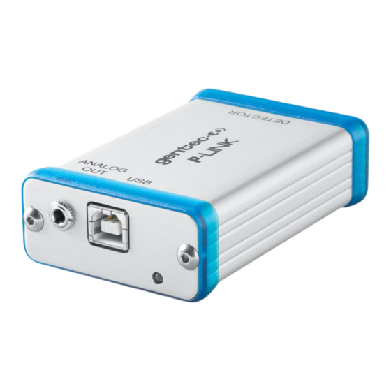
Figure 1 P-LINK Top Panel EXTERNAL POWER SUPPLY INPUT JACK Input voltage required: 9-12 VDC/100 mA. Note: The external power supply input is provided only for the P-LINK with the RS-232 Serial Connection Option. CAUTION Permanent damage may occur to the optical meter if an external power supply other than the GENTEC-EO 200130, 200960, SPU15A-105 or SPU15A-104 is used. - Page 8 Revision 20.0 Serial Interface Connector (USB or RS-232) P-LINK (USB): The USB P-LINK allows remote control and data transfer between the P-LINK and a computer that has a USB communication port. P-LINK (RS-232): The RS-232 P-LINK allows remote control and data transfer between the P-LINK and a computer, a terminal, or any device that has a serial communication port.
- Page 9 310 Series and PS-330 Series Version 1 and 2. Please contact your local Gentec-EO distributor or the nearest Gentec-EO office for further information. Any attempt to modify connectors of the early version heads to mate with the P-LINK can result in damage to the monitor.
-
Page 10: Operating Instructions
2.1. INSTALLING THE USB DRIVERS Plug the P-LINK into a USB port on the PC. If the PC supports USB 1.1, Windows detects the new device and prompts you for the software drivers. A window will open that says “Found New Hardware – USB Device”... -
Page 11: Quick Measurement Procedure
Block off the laser radiation to the detector. The power read by the P-LINK when no laser beam is incident on the detector may not be exactly zero. This is because the detector is not thermally stabilized OR there was a heat source in the detector’s field of view when you turned on the P-LINK. -
Page 12: Using The P-Link With Pc-Gentec-Eo
After it is transferred, open the file on your PC and follow the instructions to decompress and install it. Please refer to the PC-Gentec-EO manual also available on our website. If you try to install the same PC-Gentec-EO version twice on your computer, you will have the following warning: Installation Summary: No software will be installed or removed. -
Page 13: Serial Communication
P-LINK User Manual Revision 20.0 3. SERIAL COMMUNICATION 3.1. SERIAL COMMANDS The star(*) is part of each command Commands Description Return Example “ACK\r\r\n” *ATT Turns the attenuator correction ON when available for the detector “ACK\r\r\n” *ATF Turns the attenuator correction OFF. OFF by default. - Page 14 P-LINK User Manual Revision 20.0 “Version\t3\tName *F02 Returns more information about current status All field are separate by a TAB character “\t” \tUP55N-400W- H9\tWavelength \t1064\tTrig Level\t2.500000e- 01\tMax Analog Output \t2.047500e+00\tMode \t0\tOffset\t0\tMUL\t1.0 0000e+00\tOFF\t0.000 000e+00\tPWCStatus\ t65536\tMinScale\t24\t LinearCorr\t1\tAnticipa tion\t1\tAttenuator \t0\r\r\n” “ACK\r\r\n” *MUL Modifies the multiplication factor (+ 8 characters) Example: *MUL1.00E+01 selects a multiplication factor of 10...
-
Page 15: Error Messages
P-LINK User Manual Revision 20.0 3.2. ERROR MESSAGES “\r\r\nE01\r\r\n” Bad Command “\r\r\nE02\r\r\n” Energy Mode is not available “\r\r\nE03\r\r\n“ “\r\r\nE04\r\r\n“ The selected wavelength correction factor is not valid “\r\r\nE05\r\r\n” The connector is not connected “\r\r\nE06\r\r\n” Attenuator not available 3.3. COMMUNICATION SETTINGS... -
Page 16: Declaration Of Conformity
P-LINK User Manual Revision 20.0 4. DECLARATION OF CONFORMITY Application of Council Directive(s): 2014/30/EU The EMC Directive Manufacturer’s Name: Gentec Electro Optics, Inc. Manufacturer’s Address: 445 St-Jean Baptiste, suite 160 (Québec), Canada G2E 5N7 European Representative Name: Laser Components S.A.S. -
Page 17: Ukca Declaration Of Conformity
P-LINK User Manual Revision 20.0 5. UKCA DECLARATION OF CONFORMITY Application of Council Directive(s): 2014/30/EU The EMC Directive Manufacturer’s Name: Gentec Electro Optics, Inc. Manufacturer’s Address: 445 St-Jean Baptiste, suite 160 (Québec), Canada G2E 5N7 European Representative Name: Laser Components S.A.S. -
Page 18: Appendix A - Weee Directive
This section is used by the recycling center when the monitor reaches its end of life. Breaking the calibration seal or opening the monitor will void the solo warranty. The complete Monitor contains: 1 Monitor 1 power supply for RS-232 option (not made by Gentec-EO). 1 USB cable for USB option. 1 calibration certificate Separation Paper: Manual and certificate Plastic: Monitor side enclosure.
Need help?
Do you have a question about the P-LINK and is the answer not in the manual?
Questions and answers