Table of Contents
Advertisement
Quick Links
Advertisement
Table of Contents

Related Manuals for Gentec-EO MIRO ALTITUDE


Summary of Contents for Gentec-EO MIRO ALTITUDE
- Page 1 User Manual – MIRO ALTITUDE Revision 1...
- Page 2 The warranty does not cover damages related to battery leakage or misuse. Gentec-EO Inc. will repair or replace, at Gentec-EO Inc.’s option, any MIRO ALTITUDE that proves to be defective during the warranty period, except in the case of product misuse.
- Page 3 Revision 1 SAFETY INFORMATION Do not use the MIRO ALTITUDE if the device or the detector seems to be damaged or if you believe that the MIRO ALTITUDE is not working properly. Appropriate installation must be done for water-cooled and fan-cooled detectors. Refer to the specific instructions for more information.
-
Page 4: Table Of Contents
User Manual – MIRO ALTITUDE Revision 1 TABLE OF CONTENTS MIRO ALTITUDE: LASER POWER AND ENERGY METER .............. 5 ..........................5 NTRODUCTION ´ MIRO ALTITUDE ................5 S INCLUDED WITH YOUR ........................6 UICK LAUNCH GUIDE ..........................9 PECIFICATIONS ......................11 ECHANICAL DESCRIPTION USER INTERFACE ..........................15 ...................... -
Page 5: Miro Altitude: Laser Power And Energy Meter
Built-in file manager to save and view your recorded measurement sessions To obtain optimum results from your MIRO ALTITUDE meter, we suggest you to carefully read this manual. This user manual corresponds to MIRO ALTITUDE software version 1.00.06 Software updates will be provided on the Gentec-EO website: www.gentec-eo.com/products/miro-altitude... -
Page 6: Quick Launch Guide
Section 2. Quick procedure to measure power and energy: 1. Press the power button of the MIRO ALTITUDE to turn it on, which is in the upper right part of the front of the device. 2. Connect the power or energy detector to the input port of the MIRO ALTITUDE. - Page 7 (See section 2.3.6.1 for more details) Zero offset The power measurement of the MIRO ALTITUDE might not be exactly zero even if there is no laser beam on the sensor. The "ZERO" button sets the detector’s current value to zero. Subsequent measurements will be taken based on this new zero power level.
- Page 8 User Manual – MIRO ALTITUDE Revision 1 Session playback The view function ( ) in the file manager displays recorded data such as screenshots and recordings that are stored on the internal memory and on a USB drive. (See the relevant section for more details)
-
Page 9: Specifications
User Manual – MIRO ALTITUDE Revision 1 1.4 SPECIFICATIONS The following specifications are based on a one-year calibration cycle, an operating temperature of 18 to 28 °C (64 to 82 °F) and a maximum relative humidity of 80%. POWER METER SPECIFICATIONS... - Page 10 User Manual – MIRO ALTITUDE Revision 1 GENERAL SPECIFICATIONS User input correction factors 1 multiplier and 1 offset (7 significant figures, floating comma) 0 – 5 V, full scale, ± 1% Analog output External trigger Signal from 2.5 V to 24 VDC...
-
Page 11: Mechanical Description
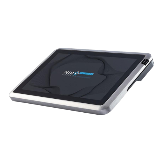
User Manual – MIRO ALTITUDE Revision 1 1.5 MECHANICAL DESCRIPTION Front panel of the MIRO ALTITUDE Top panel of the MIRO ALTITUDE Left side panel of the MIRO ALTITUDE... - Page 12 2. Touchscreen The MIRO ALTITUDE has a 10.1” multi touchscreen with an active surface of 217.56 (L) x 136.2(H) mm. To clean your screen, it is recommended to use a cleansing cloth or a soft, dry, and lint-free cloth. If necessary, you can humidify the cloth with one of the following elements: water, isopropyl alcohol (IPA) 70% or lower, or a cleaner for eyeglasses.
- Page 13 The user must specify the maximum output voltage and the maximum value of the power or energy range through the MIRO ALTITUDE application or the series commands. The measured power or energy is then converted to output voltage considering the measurement range specified according to the following equation: = (Measurement ×...
- Page 14 Through the USB-C communication port, a computer can receive data from the MIRO ALTITUDE and control it remotely. The USB-C port can be used for charging the MIRO ALTITUDE. To charge the battery while the device is running, at least 18 W is required.
-
Page 15: User Interface
To help you explore the different menus, the following image illustrates the MIRO ALTITUDE user interface structure. The items highlighted in blue are the 3 display modes. Only one is active at a time. - Page 16 User Manual – MIRO ALTITUDE Revision 1 Different buttons and icons allow you to interact with the MIRO ALTITUDE user interface. The following table describes the different buttons and icons on the MIRO ALTITUDE. Measurement menu (Display menu) Icon Name...
- Page 17 User Manual – MIRO ALTITUDE Revision 1 Bar graph Button Opens the bar display Icon and Displays the maximum measured value since the Maximum Indicator last reset Icon and Displays the minimum measured value since the Minimum Indicator last reset...
- Page 18 Analog output Button Opens the analog output settings menu Opens the measurement triggering level settings Trigger Button menu About Button Opens the MIRO ALTITUDE information menu File manager Icon Name Type Description Local storage Button Opens the on-board storage folder...
-
Page 19: Control Center
2.2.2 Navigation The control center allows the user to quickly access the three main interfaces of the MIRO ALTITUDE by pressing the corresponding buttons. The active interface is identified with a blue border. When the instrument is turned on, it enters the Display interface. - Page 20 The detector connection panel then shows the specific information of the detector. In this section you will find the detector’s connection type, its name, its serial number, its calibration date, its next calibration due date, and a “DISCONNECT” button that will disconnect the detector from the MIRO ALTITUDE.
-
Page 21: Display
The following button will appear in the lower part of the screen saying that the operation has been successful, and a direct link will also show up to see the screenshot as stored in the internal file system of the MIRO ALTITUDE. - Page 22 The MIRO ALTITUDE has an internal memory with enough space to store many recordings. It is possible to record directly on a USB drive or in the MIRO ALTITUDE’s internal memory. See the FILE MANAGER section for how to move recorded files. It is possible to set the default recording settings to facilitate data recording. To do this, please refer to the Settings menu section of this manual.
- Page 23 User Manual – MIRO ALTITUDE Revision 1 The sample duration defines the time during which the MIRO ALTITUDE will perform the data recording. Available time units are: second, minute, hour, and day. By default, the duration is 10 minutes. Minimum duration is 1 second and maximum duration is 10 days.
- Page 24 Finally, it is possible to define where the recording will be saved. By default, the recordings will be stored in the internal memory of the MIRO ALTITUDE, but it is also possible to record directly on a USB drive. Of course, you...
-
Page 25: Measurement Settings Panel
14. Battery The MIRO ALTITUDE has a Lithium-Ion battery that offers 6 hours of running time. The status of the battery is represented by an icon and a percentage that indicates the available capacity. When the low battery icon appears (<... - Page 26 2 % of the current range will not be detected. To be able to measure the lowest energies, manually set the range at the lowest level, and then select the automatic range. By doing this, the MIRO ALTITUDE will start in the lowest scale, then automatically select higher scales as necessary;...
- Page 27 ⬧ Energy (joules) *This function allows measuring the energy contained in a laser pulse using a Gentec-EO thermal power detector. This operating mode gives access to the same options as energy detectors. The only restriction is that the delay between the pulses must be compatible with the power detector’s specifications. (Please refer to the user guide for the specific power detector you are using).
- Page 28 By using advanced algorithms and known physical properties of the detector, this function allows the MIRO ALTITUDE to provide a very accurate power measurement faster than the natural response of a thermopile power detector. It accelerates the natural response by a factor of up to 10. Turning off the anticipation will result in a slower response but will reduce the noise level and provide a more stable measured value in a noisy environment.
-
Page 29: Display Area
Thermal noise is caused by a detector that has not been thermally stabilized, or there was a heat source in the field of view of the detector when the MIRO ALTITUDE was turned on (for example, the hand or body of the user). - Page 30 User Manual – MIRO ALTITUDE Revision 1 Scope display (scrolling graph) The scope display gives a quick look at the laser beam’s long-term stability and trend as a function of time (as could be seen on an oscilloscope). The chart’s x-axis is 60 seconds. When at least one minute of recording has passed, the chart will scroll to show the most recent 60 seconds of data.
- Page 31 User Manual – MIRO ALTITUDE Revision 1 Needle display Needle display is a simple and intuitive way to view the measured value. It is an excellent tool for laser tuning or alignment. The deflection of the digital needle is proportional to the real-time measurement. The 0 is on the left- hand side of the dial, whereas the range’s maximum value is on the right-hand side.
-
Page 32: Statistics
User Manual – MIRO ALTITUDE Revision 1 Bar display This display features a large band that fills up in blue from left to right according to the measurement. The current measurement value is displayed in larger digits than in the scope and needle displays. Once again, the minimum and maximum values are indicated by the small white triangles. - Page 33 User Manual – MIRO ALTITUDE Revision 1 ✓ ✓ Minimum value Lowest value in the sample period, E or P ✓ ✓ RMS stability Root mean square stability represents the standard deviation as a percentage of the average. ...
-
Page 34: File Manager
File management The file manager shows the content of the internal memory of your MIRO ALTITUDE (local storage) and of any USB drives connected to the device (USB storage). In the file manager, you can: rename files and folders, delete them, move, or copy them to a USB drive to analyze the data on a PC or to share them with your colleagues. - Page 35 User Manual – MIRO ALTITUDE Revision 1 Alphabetic order sort File size sort in increasing order The items that are displayed in the file manager can be of three types: "Folder", "Session”, and "Screenshot". For the last two, we can see a button ( ) that opens a session recording or a screenshot directly on the MIRO ALTITUDE when tapped.
-
Page 36: Internal Memory
USB drive A USB drive (ideally in FAT32 format) can be plugged into to the MIRO ALTITUDE at any time. The file manager will be updated to show the "USB storage" drive. Files can be copied from the local storage drive to the external drive. -
Page 37: File And Folders Management
The "Rename" option allows you to rename this file or folder. The "Move" option will move a file or a folder and its contents to your USB drive. This option is only available if a USB drive is connected to your MIRO ALTITUDE. - Page 38 User Manual – MIRO ALTITUDE Revision 1 The choices in this menu are updated according to the items selected. To exit multi selection mode, tap on the button above the item list. Folders can also be created from the More options menu.
-
Page 39: Viewing Screenshots And Data Recordings
.txt file log, when the log file is opened in a text editor on a PC: On your MIRO ALTITUDE, the user can press on the graph to see a vertical cursor that indicates the measurement at that point. - Page 40 User Manual – MIRO ALTITUDE Revision 1 When the recording time is longer than the available time range, you can slide your finger on the time range to scroll through the data. To exit the recording viewer, press on "EXIT" in the upper part of the screen and confirm...
-
Page 41: Settings
The settings menu allows the user to configure and save several useful settings that will help make the most of the MIRO ALTITUDE. You can configure the recorded data, the Ethernet connection, the RS232 connection, the analog output and the measurement trigger level. In addition, the “About” menu contains information on the MIRO ALTITUDE. - Page 42 After the screen has not been touched for the specified amount of time, its brightness is reduced for 10 seconds, and then the display turns off completely. The MIRO ALTITUDE keeps working normally when the screen is off: if a recording is in progress, it will not be interrupted. Turn the screen back on with a short press on the power button.
-
Page 43: Recording
User Manual – MIRO ALTITUDE Revision 1 This setting changes the number of digits after the comma that are displayed when making a measurement. Press on the button to show the list of options. The default setting lets the device choose the best option according to the range. -
Page 44: Ethernet
2.5.4 RS232 The RS232 settings manage the parameters for RS232 communication with MIRO ALTITUDE. For the moment, these settings can be viewed but cannot be modified. These settings will be available soon in a new software update that will be accessible for download on the Gentec-EO website. -
Page 45: Analog Output
Analog output The analog output settings allow the user to obtain a signal coming from the MIRO ALTITUDE by using external equipment, such as a continuous line recorder, a computer with an analog interface, a voltmeter, etc. To use this feature, use a standard BNC cable. - Page 46 User Manual – MIRO ALTITUDE Revision 1 To select the input signal that comes from the detector, you must press on “selected measurement.” The following menu will appear. The unit will be determined according to the connected detector. For a wattmeter, the unit will be W for watt and for a joulemeter the unit will be J for joule.
-
Page 47: Trigger
When the external trigger is activated, the trigger level option turns grey as it is not used. The external trigger allows connecting an external device such as a laser with a trigger output to the MIRO ALTITUDE to trigger the pulse measurement. - Page 48 3 J will be measured. Warning: If you select a trigger level with a high value, the MIRO ALTITUDE might not be able to detect all the pulses of widely varying energy levels in auto range mode. The auto range function uses the energy level of the last measured pulse to establish the range level.
-
Page 49: About
This information will tell you if your device is up to date. If you must get in touch with one of our representatives regarding your MIRO ALTITUDE, they may ask you to... - Page 50 User Manual – MIRO ALTITUDE Revision 1...
-
Page 51: Serial Communication
The MIRO ALTITUDE USB port is classified as a COM port by your computer, although it is a USB port. You can send serial commands to this port leveraging the highest speed of a USB that the computer may allow. USB drivers are entirely tested and digitally approved by Microsoft. -
Page 52: Serial Commands Format
This facilitates the data export to a spreadsheet. 3.4 LIST OF SERIAL COMMANDS FOR THE MIRO ALTITUDE DEVICE The MIRO ALTITUDE supports all the following commands:... -
Page 53: Detailed Descriptions Of The Series Commands For The Miro Altitude
The characters do not have to be uppercase and mixed case is OK. Replies to all text mode commands are also in text mode, and end with a carriage-return and linefeed. 3.5 DETAILED DESCRIPTIONS OF THE SERIES COMMANDS FOR THE MIRO ALTITUDE 3.5.1... -
Page 54: Data Acquisition
User Manual – MIRO ALTITUDE Revision 1 *GCR - Get Current Scale Index This command returns the scale index between 24 and 61. Please refer to Set Scale command (SCS) details for the complete scale index table. Command Settings Answer... - Page 55 User Manual – MIRO ALTITUDE Revision 1 Examples For example, a 506.601W reading and a -12.25631mW reading would be displayed like this: Command: *CVU Answer: +5.066010e+02<CR><LF> Command: *CVU Answer: -1.225631e-02<CR><LF> *CAU - Send Continuous Transmission of Data This command is used to send data to the serial port according to the data sampling setting. For Joulemeters, the data can also be in binary format (refer to section 4.4)
-
Page 56: Setup
User Manual – MIRO ALTITUDE Revision 1 3.5.3 Setup *PWC - Set Personal Wavelength Correction in nm This command is used to specify the wavelength in nm being used on the detector. The EEPROM in the detector contains measured spectral data for a wide range of wavelengths. A valid value is set between the lowest and highest wavelengths supported by the device, and it should not be a floating-point value. - Page 57 User Manual – MIRO ALTITUDE Revision 1 Example The following example activates the anticipation. Command: *ANT1 Answer: *GAN - Get Anticipation Status This command returns the anticipation status. If the anticipation is not available, it will always be “off”. Command...
- Page 58 User Manual – MIRO ALTITUDE Revision 1 *MUL3.3000e1 *GUM - Get User Multiplier This command allows returning the value of the multiplier. Command Settings Answer None Current multiplier value Example Answer: Command: *GUM User Multiplier: 1.0000000E+00<CR><LF> *OFF - Set User Offset This command is used to set the value of the user-specified offset.
- Page 59 User Manual – MIRO ALTITUDE Revision 1 *SSE - Set Single Shot Energy Mode This command is used to toggle to Single Shot Energy Mode when using a wattmeter. It is recommended to wait at least 2 seconds after this command before sending another command, to avoid communication problems.
-
Page 60: Instrument And Detector Information
User Manual – MIRO ALTITUDE Revision 1 3.5.5 Instrument and detector information *VER - Query Version This command is used to query the device to get information about the firmware version and the device type. Command Settings Answer None Version and device type... - Page 61 00 00 0000 = Null termination character 0000 00 00 End of the structure *GFW - Software version request This command returns the number of the onboard firmware installed on the MIRO ALTITUDE. Command Settings Answer None Firmware version number...
-
Page 62: Error Messages
User Manual – MIRO ALTITUDE Revision 1 3.6 ERROR MESSAGES Error Description Command Error. Command not recognized. Command is invalid. Command Error. Command must start with '*' All text commands must begin with a trig character (*). Detector not present Detector head must be attached to execute this command. -
Page 63: Declaration Of Conformity
User Manual – MIRO ALTITUDE Revision 1 DECLARATION OF CONFORMITY Application of the Council Directives(s): 2014/30/EU EMC Directive Manufacturer’s Name: Gentec Electro-Optics, inc. Manufacturer’s Address: 445, St-Jean-Baptiste, office 160 (Québec) Canada G2E 5N7 European Representative’s Name: Laser Components S.A.S Representative’s Address:... - Page 64 User Manual – MIRO ALTITUDE Revision 1 Product regulations...
- Page 65 User Manual – MIRO ALTITUDE Revision 1 I, the undersigned, hereby declare that the equipment specified above conforms to the above Directive(s) and Standard(s) Place: Québec Date: Wednesday, April 14, 2021 (President)
-
Page 66: Ukca Declaration Of Conformity
User Manual – MIRO ALTITUDE Revision 1 UKCA DECLARATION OF CONFORMITY Application of the Council Directives(s): 2014/30/EU EMC Directive Manufacturer’s Name: Gentec Electro-Optics, inc. Manufacturer’s Address: 445, St-Jean-Baptiste, office 160 (Québec) Canada G2E 5N7 European Representative’s Name: Laser Components S.A.S Representative’s Address:... - Page 67 User Manual – MIRO ALTITUDE Revision 1 Product regulations...
- Page 68 User Manual – MIRO ALTITUDE Revision 1 I, the undersigned, hereby declare that the equipment specified above conforms to the above Directive(s) and Standard(s) Place: Québec Date: Wednesday, May 25, 2022 (President)
-
Page 69: Weee Directive
Recycling and sorting procedure from WEEE Directive 2002/96/EC This section is meant for the recycling center when the detector has reached its end life. Breaking the calibration seal or opening the device will void the MIRO ALTITUDE’s warranty. Sorting Paper: Manual and certificate... - Page 70 User Manual – MIRO ALTITUDE Revision 1...
Need help?
Do you have a question about the MIRO ALTITUDE and is the answer not in the manual?
Questions and answers