
Related Manuals for ZKTeco InBio Pro Plus Series


Summary of Contents for ZKTeco InBio Pro Plus Series
- Page 1 Quick Start Guide InBio Pro Plus Series Version: 1.0 Due to regular upgrades of systems and products, ZKTeco could not guarantee exact consistency between the actual product and the written information in this manual.
- Page 2 1. Cautions Please note the following cautions. Mis-operation may lead to any injury or equipment failure: 1. Do not energize the system before installation is complete; never carry out installation activities when the system is energized. 2. All peripheral devices must be grounded. 3.
-
Page 3: Product Dimension
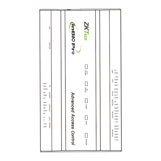
2. Product Dimension InBio160 Pro Plus InBio260 Pro Plus InBio460 Pro Plus 8.90in SGND (226.0mm) 7.29in 7.29in (185.1mm) (185.1mm) 4.17in (106.0mm) 4.17in (106.0mm) 4.17in (106.0mm) 1.42in 1.42in 1.42in (36.0mm) (36.0mm) (36.0mm) 1.42in 1.42in 1.42in (36.0mm) (36.0mm) (36.0mm) - Page 4 Metal Enclosure Cable Conduit (Punch Hole for cables) LED Status Indicator Advanced Access Control POWER COMM Heat Lock Dissipation Grill 3.543in (90.0mm) Metal Enclosure Tamper Switch Mounting Holes DIN Rail Mounting Holes 11.811in(300.0mm) Metal Enclosure Mounting Holes 13.780in (350.0mm)
- Page 5 3. Installation of Metal Enclosure on the wall 1. According to the mounting holes position of the metal enclosure. Drill three mounting holes in a suitable spot on the wall and make sure it is about 114 inches (2.9m) above the ground, which can be adjusted according to actual needs.
- Page 6 4. LED indicators, Wires, Auxiliary Input and Output 1) Understanding the LED indicators: RUN indicator (green): Flashing indicates the system works normally. CARD indicator (yellow): Flashing indicates card is punched on reader. LINK indicator (green): Always (green) indicates TCP/IP communication is proper. 2) Recommended use of wires: ACT indicator (yellow): Flashing indicates data is in trans- Use 2-conducotor power cord...
- Page 7 InBio260 Pro Plus InBio460 Pro Plus SD Card Slot SD Card Slot Function: Backup Access Control Logs Function: Backup Access Control Logs Ethernet Auxiliary input Ethernet (1-2) interface Auxiliary input (1-4) Extended RS485 DIP switche DIP switch Status indicator Extended RS485 PC RS485 PC RS485 interface...
- Page 8 5. Controller System Installation Exit Button ProID 102 Touch EXIT Aux. Input Wiegand STATE RS485 RS485 inBio Pro Plus Series TCP/IP SWITCH TCP/IP TCP/IP Aux. Ouput OSDP KF1200 Pro OSDP Door Sensor Door Sensor Door Sensor 485- 485+ QR500 FR1500S...
-
Page 9: Power Connection
6. Power Connection Without Backup Battery POWER STATE RS485 RS485 SWITCH BT+ BT- Ground Switching Power Supply With Backup Battery POWER STATE RS485 RS485 SWITCH BT+ BT- Ground Backup Battery Switching Power Supply... -
Page 10: Ethernet Connection
7. Ethernet Connection Establish the connection between the device and the software using an Ethernet cable. An illustrative example is provided below: Default IP address: 192.168.1.201 Subnet mask: 255.255.255.0 IP address: 192.168.1.130 Subnet mask: 255.255.255.0 TCP/IP TCP/IP Note: In LAN, IP addresses of the server (PC) and the device must be in the same network segment when connecting to the software. -
Page 11: Auxiliary Input Connection
9. Auxiliary Input Connection STATE RS485 RS485 SWITCH TCP/IP +12V DC 12V DC TCP/IP Fire Alarm 10. Auxiliary Output Connection STATE AUXOUT RS485 RS485 SWITCH TCP/IP +12V DC TCP/IP Alarm... -
Page 12: Exit Button Connection
11. Exit Button Connection STATE BUTTON1 RS485 RS485 SWITCH TCP/IP Button Exit Button TCP/IP 12. RS485 Connection STATE Baud Rate: RS485 RS485 ZK485: 115200 OSDP: 115200 SWITCH 485+ 485- TCP/IP +12V DC +12V DC +12V DC +12V DC TCP/IP #8 QR500 #3 FR1500S #2 KF1200 #1 ProID 103... - Page 13 Controller Supported Reader Models: Reader Model 485 Unencrypted 485 Encryption OSDP Unencrypted OSDP Encryption KF1100 Pro/KF1200 Pro FR1200/FR1500S ProID101/102/103/104 QR50/QR500/QR600 Remarks: means connectable, means not connectable. 2. T he KF1000 Pro series reader support s tamper alarm function in both encryption and unencrypted modes of 485 communication.
- Page 14 13. Connecting EX0808 via PC485 STATE RS485 RS485 SWITCH OSDP TCP/IP 485- 485+ TCP/IP +12V DC +12V DC +12V DC #1 EX0808 #2 EX0808 #8 EX0808 Important Notes: 1. Conf igure the ZK485 protocol through the PC485 port to connect up to eight EX0808 expansion boards to expand a certain number of auxiliary inputs and auxiliary outputs.
- Page 15 DIP Switch Setting for RS485/OSDP Communication RS485 RS485 RS485 Description DIP Switch DIP Switch DIP Switch Address Address Address 1 2 4 8 MODE (RS485/OSDP) RS485 Terminal Resistance Important Notes: There are six DIP switches on the EX0808 expansion board and their functions are: 1.
-
Page 16: Lock Relay Connection
14. Lock Relay Connection Controller not sharing power with the lock LOCK1 STATE RS485 RS485 Sensor SWITCH +12V DC Sensor Door Sensor TCP/IP Lock Power +12V DC 12V DC FR107 TCP/IP Normally Closed Lock Do not reverse the polarity. Switching dry and wet modes Important Notes: Dry Mode supports separate power supply for the lock using an external independent power supply. - Page 17 Controller sharing power with the lock Normally Opened Lock Powered From Lock Terminal: STATE LOCK LOCK1 RS485 RS485 SWITCH +12V DC +12V DC 12V DC TCP/IP 12V DC FR107 TCP/IP Do not reverse the polarity. Normally Opened Lock Normally Closed Lock Powered From Lock Terminal: STATE LOCK LOCK1...
-
Page 18: Dip Switch Setting
15. DIP Switch Setting STATE 1 2 3 4 5 6 7 8 RS485 RS485 SWITCH 1 2 4 8 16 32 RS485 Terminal Resistance 1. Number 1-6 are reserved to set the device number for RS485 communication. The code is binary, and the numbering starts from left to right. -
Page 19: Restore Factory Setting
Restore Factory Setting 1. If you forget the IP address of the InBio Pro Plus series panel or the device does not work normally, you can use the number 7 DIP switch to restore it to factory default settings. The parameters which gets reset are device IP address, communication password, gateway, and subnet mask. -
Page 20: Troubleshooting
17. Troubleshooting 1. How to switch four door one way to two door two way? Connect four readers from reader 1 to reader 4. Connect two door locks, one connected to LOCK1, another connected to LOCK3. In the software conf igure reader 1-Indoor, and reader 2-Outdoor. Note: Please note that below option is only available in software version 3.0.3.1 or above. - Page 21 ZKTeco Industrial Park, No. 32, Industrial Road, Tangxia Town, Dongguan, China. Phone : +86 769 - 82109991 : +86 755 - 89602394 www.zkteco.com Copyright © 2024 ZKTECO CO., LTD. All Rights Reserved.
Need help?
Do you have a question about the InBio Pro Plus Series and is the answer not in the manual?
Questions and answers