Sign In
Upload
Download
Table of Contents
Contents
Add to my manuals
Delete from my manuals
Share
URL of this page:
HTML Link:
Bookmark this page
Add
Manual will be automatically added to "My Manuals"
Print this page
×
Bookmark added
×
Added to my manuals
Manuals
Brands
Deye Manuals
Inverter
SUN600G
Installation & user manual
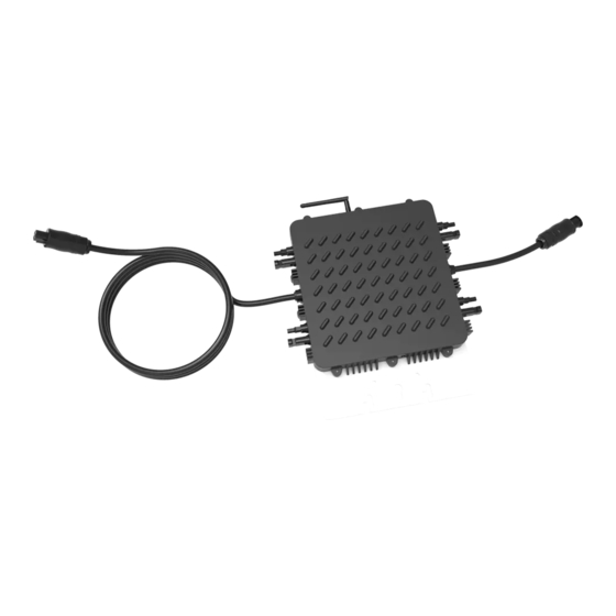
Deye SUN600G Installation & User Manual
Photovoltaic grid-connected microinverter
Hide thumbs
1
Table Of Contents
2
3
4
5
6
7
8
9
10
11
12
13
14
15
16
17
18
19
20
21
22
23
page
of
23
Go
/
23
Contents
Table of Contents
Troubleshooting
Bookmarks
Table of Contents
Table of Contents
Important Safety Instructions
Safety Instructions
Radio Interference Statement
Communication Statement
Symbols Replace Words on the Equipment, on a Display, or in Manuals
Microinverter System Introduction
Microinverter Introduction
Microinverter System Installation
Additional Installation Components
Required Parts and Tools from You
Installation Procedures
Step 1 - Install the AC Branch Circuit Junction Box
Step 2 - Attach the Microinverters to the Racking or the PV Module Frame
Stpe 3 - Connect the Microinverters in Parallel
Step 4 - Install a AC Protective End Cap at the End of AC Cable
Step 5 - Connect Microinverters to the PV Modules
Microinverter System Operating Instructions
Troubleshooting
Status Indications and Error Reporting
Start up LED
Operation LED
GFDI Error
Other Faults
Troubleshooting a Non-Operating Microinverter
Maintenance
Replace a Microinverter
Technical Data
SUN600G Microinverter Datasheet
SUN1300G Microinverter Datasheet
Wiring Diagram
Sample Wiring Diagrams
Advertisement
Quick Links
1
Microinverter System Installation
2
Status Indications and Error Reporting
3
Maintenance
4
Sun600G Microinverter Datasheet
5
Sun1300G Microinverter Datasheet
6
Sample Wiring Diagrams
Download this manual
Installation / User Manual
Model SUN600G&SUN1300G
Photovoltaic Grid-connected Microinverter
Rev 1.3
© All Rights Reserved
Table of
Contents
Previous
Page
Next
Page
1
2
3
4
5
Advertisement
Table of Contents
Troubleshooting
Troubleshooting
14
Troubleshooting a non-operating Microinverter
15
Need help?
Do you have a question about the SUN600G and is the answer not in the manual?
Ask a question
Questions and answers
Related Manuals for Deye SUN600G
Inverter Deye SUN300G3-EU-230 Installation & User Manual
Photovoltaic grid-connected microinverter, external wifi-g3 (24 pages)
Inverter Deye SUN Series Installation & User Manual
Photovoltaics grid-connected microinverter with built-in wifi-g3 (30 pages)
Inverter Deye SUN-60K-G User Manual
Grid-tied pv string inverter (53 pages)
Inverter Deye SUN-70K-G User Manual
(54 pages)
Inverter Deye SUN-80K-G User Manual
Grid-tied pv string inverter (45 pages)
Inverter Deye SUN-60K-G User Manual
Grid-connected pv inverter (67 pages)
Inverter Deye SUN-60K-G03 User Manual
Grid-connected pv inverter (67 pages)
Inverter Deye SUN-30K-G03 User Manual
Grid-connected pv inverter (79 pages)
Inverter Deye SUN-60K-G01P3-EU-AM8-LV User Manual
Grid-connected pv inverter (67 pages)
Inverter Deye SUN-60K-G04P3-EU-AM4 User Manual
Grid-connected pv inverter (67 pages)
Inverter Deye SUN-60K-SG02HP3-EU-EM6 User Manual
Hybrid inverter (61 pages)
Inverter Deye SUN-70K-SG02HP3-EU-EM6 User Manual
Hybrid inverter (63 pages)
Inverter Deye SUN-3.6K-G User Manual
Grid-connected pv inverter (46 pages)
Inverter Deye SUN-8K-SG04LP3-EU User Manual
Hybrid inverter (58 pages)
Inverter Deye SUN-6K-SG03LP1-EU User Manual
(51 pages)
Inverter Deye SUN-6K-G05P1-EU-AM2 User Manual
Grid-connected pv inverter (67 pages)
This manual is also suitable for:
Sun1300g
Table of Contents
Print
Rename the bookmark
Delete bookmark?
Delete from my manuals?
Login
Sign In
OR
Sign in with Facebook
Sign in with Google
Upload manual
Upload from disk
Upload from URL


Need help?
Do you have a question about the SUN600G and is the answer not in the manual?
Questions and answers