Advertisement
Table of Contents
- 1 Table of Contents
- 2 Parts List
- 3 Installation to Wood Joist Finished Ceilings, Exposed Wood Joists, or Wood Beam Ceilings
- 4 Installation to Concrete Ceilings
- 5 Flush Mount Application
- 6 Installation to Extension Columns
- 7 Attaching Adapter Plate to Projector
- 8 Attaching Adapter Plate to Projector Mount, Projector Alignment
- Download this manual
Advertisement
Table of Contents

Related Manuals for peerless-AV Vector Pro II PJF2-UNV


Summary of Contents for peerless-AV Vector Pro II PJF2-UNV
- Page 1 Installation and Assembly Manual: Vector Pro II™ Models: PJF2-UNV, PJF2-UNV-S This product is intended for use with UL Listed products and must be installed by a qualified professional installer. Maximum UL Load Capacity: 50 lb (27 kg)
-
Page 2: Table Of Contents
Note: Read entire instruction sheet before you start installation and assembly. WARNING • Do not begin to install your Peerless product until you have read and understood the instructions and warnings con- tained in this Installation Sheet. If you have any questions regarding any of the instructions or warnings, call Peerless customer care at 1-800-729-0307. -
Page 3: Parts List
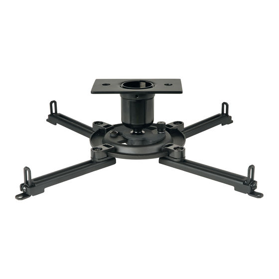
Before you start check the parts list to insure all of the parts shown are included. Parts List PJF2-UNV PJF2-UNV-S Description Qty. Part # Part # ball and socket mount 055-0011 055-0016 adapter plate 055-1867 055-4867 ceiling plate 580-1042 580-4042 extension column connector with cord management 580-1025 580-4025... -
Page 4: Installation To Wood Joist Finished Ceilings, Exposed Wood Joists, Or Wood Beam Ceilings
Installation To Wood Joist Finished Ceilings, Exposed Wood Joists, or Wood Beam Ceilings Drill two 5/32" (4 mm) dia. holes to a minimum depth of 2.5" (64 mm). Attach ceiling plate (C) with two #14 x 2.5" (6 mm x 65 mm) wood screws (H) as shown using 3/8"... -
Page 5: Installation To Concrete Ceilings
WARNING • When installing Peerless wall mounts on concrete, verify that you have a minimum of 1 5/8" of actual concrete surface in the 1/4" diameter hole to be used for the concrete anchors. Do not drill into mortar joints! Concrete must meet ASTM C-90 specifications. -
Page 6: Flush Mount Application
Flush Mount Application Screw ball and socket mount (A) into ceiling plate (C). Align the notch with one of the four holes of the ceiling plate (C) and secure ball and socket mount (A) with a M5 x 10 mm socket pin screw (E) using security allen wrench (U) as shown in detail 1. -
Page 7: Installation To Extension Columns
Installation to Extension Column Screw extension column to ceiling plate (C). Align the notch with one of the four holes in the ceiling plate (C) and secure extension column with a M5 x 10 mm socket pin screw (E) using security allen EXTENSION COLUMN wrench (U). -
Page 8: Attaching Adapter Plate To Projector
Attaching Adapter Plate to Projector NOTE: The projector you are installing may differ in appearance from the sample illustrated below. Place projector upside down. Locate adapter plate (B) with notch facing forward as close to projector center of gravity as possible without covering any mounting holes. Loosen channels, and if there are only three mounting holes remove fourth channel. -
Page 9: Attaching Adapter Plate To Projector Mount, Projector Alignment
Attaching Adapter Plate to Projector Mount Attach projector, with adapter plate (B) already on it, to To adjust roll, pitch, and yaw loosen the set screw the ball and socket mount (A) by inserting the ball and (shown below) using security allen wrench (U) or socket mount into the adapter plate connection and standard 4 mm allen wrench.
Need help?
Do you have a question about the Vector Pro II PJF2-UNV and is the answer not in the manual?
Questions and answers