
Related Manuals for Intermatic I-Wave PE45343RC


Summary of Contents for Intermatic I-Wave PE45343RC
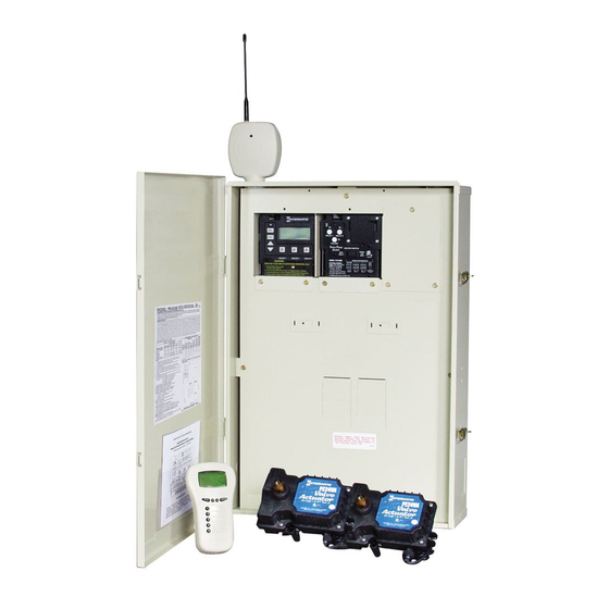
- Page 1 Wave PE5 Series Pool/Spa Combination Systems Pool Systems Spa Systems PE45343RC PE45343RCT1 PE45343RCT3 Installation and User Guide Version 4-13-06...
-
Page 2: Important Safety Instructions
WARNING: Risk of electric shock – Install the control center at least five (5) feet (152.4cm) from the inside wall of the pool and/or hot tub using non-metallic plumbing. Canadian installations must be at least three (3) meters from the water. Copyright © 2006 Intermatic, Inc. - Page 3 Safety • Children should not use spas or hot tubs without adult supervision. • Do not use spas or hot tubs unless all suction guards are installed to prevent body and hair entrapment. • People using medications and/or having an adverse medical history should consult a physician before using a spa or hot tub.
-
Page 4: Table Of Contents
Connection for Raypak Heaters .....................22 Connection for Hayward Heaters ..................23 Connection for Pentair Heater ....................23 Connection for Sta-Rite Heaters .....................24 Section 4: Programming the Three-Circuit Clock Mechanism ............25 Overview of Three Circuit Clock Control Panel................25 Copyright © 2006 Intermatic, Inc. - Page 5 Safety Identifying Connections and Selecting Proper Input Voltage ............26 Connection Detail .........................26 Circuit Ratings ..........................27 Mode Selection/Definition ......................27 Mode 1 — (Aux1, Aux2, Aux3) ....................27 Mode 2 — (Pump High, Pump Low, Aux3) ................28 Mode 3 — (Pump, Aux2, Cleaner Pump) ................28 Mode 4 —...
-
Page 6: Section 1: System Overview
I-Wave PE5 Installation Guide Section 1: System Overview The Intermatic I-Wave Pool/Spa PE5 Wireless Control System brings wireless control to a new level of simplicity and affordability. What makes the system distinctive is that it is: • Easy to Use — with simple, push button controls and a clear, easy-to-read display panel •... -
Page 7: Additional Detail On Key Components
PE45343RCT1 — a special version with a 100 watt transformer for 12-Volt underwater lighting, where required by local code. The 100-watt transformer (PA117) can also be ordered separately for installation into standard model PE45343RC. • PE45343RCT3 — a special version with a 300 watt transformer for 12-Volt underwater lighting, where required by local code. -
Page 8: Valve/Pump Switch (P4243Me)
This unit snaps into almost any Intermatic enclosure and features two 3HP double pole relays, one of which can be controlled by an external timer, 24 volt supply for... -
Page 9: Wireless Hand-Held Transceiver (Pe950)
10 Amp Tungsten, 120/240 VAC, 50/60 Hz Water Temperature Sensor (PA122) The Intermatic Water Sensor (PA122) monitors both pool and spa water temperature, depending on the position of the diverter valves. Installation is necessary for the thermostatic control to work. The sensor can be ordered separately. -
Page 10: Steel Outdoor Enclosure Includes Pe45300 (Pe45300)
Wireless Hand-Held Transceiver (PE950) can only control two mechanisms. Optional — Freeze (Air Temperature) Sensor (178PA28A) Add the Intermatic Freeze or Air Temperature Sensor (178PA28A) to installations where below-freezing outdoor temperatures are a concern. Programming information to incorporate the sensor is provided on page 35. -
Page 11: Section 2: Plumbing Examples
Two: Plumbing and Wiring Examples Section 2: Plumbing Examples The following diagrams show several plumbing and wiring examples of installations for pool and spa that share a single filter pump, filter, and heater. If you are installing a pool only or spa only, these diagrams will not apply. -
Page 12: For Non-Booster Pump Pool Cleaner Installations
I-Wave PE5 Installation Guide For Non-Booster Pump Pool Pool Pool Cleaner Installations Return Return Return Return Intake Intake Intake Intake Energy Energy Filter Filter Check Check Valve Valve Make-up Make-up Filter Filter Filter Filter Pump Pump Heater Heater Copyright © 2006 Intermatic, Inc. -
Page 13: Section 3: Control Center Installation
Three: Control Center Installation Section 3: Control Center Installation Mounting the Control Center Special code requirements apply to your I-Wave Control System. To ensure safe installation, please follow all applicable national state, and local codes when installing the Control Center. Locate your Control Center near the pool/spa equipment pad at least five feet or more away from either the pool or spa equipment and at least five feet... -
Page 14: Bonding The Control Center
Each circuit breaker should be sized according to your load and the appropriate local codes. The I-Wave Control System consists of two Intermatic snap-in mechanisms: • P1353ME — with three timed circuits each comprised of three SPST relays •... -
Page 15: If Wiring 120-Volt Loads
Three: Control Center Installation If Wiring 120-Volt Loads: • For safety purposes, the factory default setting for the source voltage of a P1353ME mechanism is for 240 Volts. • For 120-Volt installations, be sure you set the Source Voltage Selection Jumper on the back of the Three-Circuit Clock mechanism (P1353ME) for 120 Volts before you begin wiring. -
Page 16: If Wiring 240-Volt Loads
Blk/Red Blk/Red Blk/Red 240 VAC 240 VAC Line Line Blu/Yel Blu/Yel Load Load Breaker Breaker Panel Panel Filter Pump Filter Pump (240 VAC) (240 VAC) Blower Blower (240 VAC) (240 VAC) Figure 3-5 Figure 3-5 Copyright © 2006 Intermatic, Inc. -
Page 17: If Wiring Combination 120- And 240-Volt Loads
Three: Control Center Installation If Wiring Combination 120- and 240-Volt Loads: • For combination 120- and 240-Volt loads, change the factory default setting of the Source Voltage Selection Jumper on the back of the Three-Circuit Clock mechanism (P1353ME) from its factory default setting to 120 Volts. •... -
Page 18: Wiring Underwater Lights
From the LOAD side of the GFCI to the line side of the clock, From the light to the LOAD side of the clock. (See Figure 3-8.) Connect the ground (green) from the light to the grounding bar inside the Control Center. Copyright © 2006 Intermatic, Inc. -
Page 19: Low-Voltage Underwater Lights
(with a 100 watt transformer) or PE45343RCT3 (with a 300-watt transformer). Alternatively, you can order a 300-watt PA124 or 100-watt PA123 12V transformer kit to mount in the standard system model PE45343RC. (See Figure 3-10.) If required by local code, install a GFCI receptacle and connect the neutral and hot wire, from the circuit breaker, to the LINE side of the GFCI. -
Page 20: Low-Voltage Wiring
Power must be disconnected when connecting the Freeze Sensor. Only an Intermatic Freeze Sensor will work with this controller. Refer to page 35 for programming information, and page 10 for ordering information. -
Page 21: Motorized Valve Actuator Connection And Synchronizing
Motorized Valve Actuator Connection and Synchronizing The I-Wave Control System is capable of controlling up to three Motorized Valve Actuators. Two Intermatic Motorized Valve Actuators (PE24VA) are included with your I-Wave system. Refer to page 8 for information to order additional actuators. -
Page 22: Fireman Switch Connection
24 VAC @ 2A or less, in the market today. Locate your heater in the following pages and follow the instructions for proper installation with your I-Wave Control Center. Connection to the Three-Circuit Clock Connect the Fireman switch to the Intermatic Fireman Switch Fireman Fireman wires (tagged), located in the low-voltage raceway of the... -
Page 23: Connection For Hayward Heaters
Three: Control Center Installation Connection for Hayward Heaters Remove heater service door on your Hayward Heater. Remove factory-installed wire connector between two (2) red wires labeled “CONNECTION FOR FIELD INSTALLED CONTROL SWITCH.” (See Figure 3-17.) Connect two #14 gauge wires, designed for use in hot environments, to the two red wires. -
Page 24: Connection For Sta-Rite Heaters
Route the wires out through the knockout on the bottom of the Control Box. Do not disconnect high limit or pressure switches. Turn the heater on and maximize the temperature setting. Figure 3-23 Figure 3-23 Copyright © 2006 Intermatic, Inc. -
Page 25: Section 4: Programming The Three-Circuit Clock Mechanism
Mechanism Overview of Three Circuit Clock Control Panel The Intermatic Three-Circuit Clock Control Panel is easy to program and capable of automatically switching loads on three circuits according to a preset 24-hour daily schedule, and providing control over a variety of different applications. Figure 4-1 shows the front of the mechanism. -
Page 26: Identifying Connections And Selecting Proper Input Voltage
Freeze Sensor Connection — For the Intermatic Freeze Sensor (178PA28A), which is necessary for the freeze protection circuit and programming to work. Disconnect power when connecting the freeze sensor. Only an Intermatic sensor can be used. Refer to page 35 for programming information. -
Page 27: Circuit Ratings
Four: Programming the Three-Circult Clock Mechanism Circuit Ratings CLOCK SOURCE VOLTAGE — 120/240VAC, 50/60 Hz POWER CONSUMPTION — 6.0 Watts Max CIRCUIT CONTACT CONFIGURATION — SPST CIRCUIT SWITCH RATINGS ALL MODES: • 20A Resistive, 120/240 VAC, 50/60 Hz • 20A FLA@120 VAC, 96A LRA@120 VAC, 50/60 Hz •... -
Page 28: Mode 2 - (Pump High, Pump Low, Aux3)
120V or 240V. load, whether 120V or 240V. Figure 4-5 Figure 4-5 Copyright © 2006 Intermatic, Inc. -
Page 29: Mode 4 - (Pump High, Pump Low, Cleaner Pump)
Four: Programming the Three-Circult Clock Mechanism Mode 4 — (Pump High, Pump Low, Cleaner Pump) Circuit one and two are dedicated single pole outputs for a two-speed pump load. Circuits one and two will never be ON at the same time, consistent with a two-speed pump application. -
Page 30: Mode 6 - (Aux1, Aux2, Aux3)
Circuit outputs will Mode Mode press and release the <ENTER> button. This be defined be defined Number Number <Arrow> <Arrow> saves the mode number to memory and exits blinks blinks buttons buttons SET MODE programming. Copyright © 2006 Intermatic, Inc. -
Page 31: Setting Time Of Day
Four: Programming the Three-Circult Clock Mechanism Setting Time of Day Overview This procedure makes sure that timer-controlled actions will occur at the right time. AM/PM Indicator AM/PM Indicator Program Menu Program Menu Procedure Displayed Time Displayed Time <PROGRAM> <PROGRAM> NOTE: If you don’t press a button within 60 seconds button button while setting Time of Day, the control will save... - Page 32 • If the ON/OFF button is pressed while the corresponding circuit is on, it turns the circuit off and supersedes any program in progress. The priority is always given to the last manual operation. Copyright © 2006 Intermatic, Inc.
- Page 33 Four: Programming the Three-Circult Clock Mechanism Notes on Setting ON/OFF Times for Each Mode (cont’d) Mode 1 — (Aux1, Aux2, Aux3) All three of the available circuits act independently, and up to three individual on/off times can be set for each circuit independently. Mode 2 —...
-
Page 34: Setting The Heater's Cool Down Time (Optional)
NOTE: You can override the Cool Down feature during countdown by pressing and releasing the ON/OFF button associated with Circuit #1. This will end the cool down cycle and immediately power off Circuit #1. Copyright © 2006 Intermatic, Inc. -
Page 35: Setting Freeze Temperature (Optional)
(178PA28A) has been installed. This is the only freeze sensor that will work with the P1353ME Mechanism. Power must be disconnected when connecting the 178PA28A sensor. If Intermatic Freeze Sensor (178PA28A) has been installed, use the following procedure to program freeze temperature. Procedure Use the <PROGRAM>... -
Page 36: Section 5: Programming The Valve/Pump Switch Mechanism
CIRCUITS 1 & 2 — The pool to spa mechanism switch, etc.). See page 38 for supports up to two auxiliary 3HP circuit loads. You details. can have different source voltages for each circuit, depending on your equipment requirements. Copyright © 2006 Intermatic, Inc. -
Page 37: Rear View
Five: Programming the Valve/Pump Switch Mechanism Rear View HEATER SWITCH CONNECTION — The POOL/SPA & SPA ONLY HEATER SWITCH CONNECTION — The POOL/SPA & SPA ONLY 24 VAC POWER-IN FOR PC 24 VAC POWER-IN FOR PC switch, located on the face of the Valve/Pump Switch mechanism, switch, located on the face of the Valve/Pump Switch mechanism, BOARD —... -
Page 38: Installing The Three-Button Wired Remote Control
Valve/Pump Switch control panel, your changes will be temporary with the wired remote switch (master switch) because it will return the circuits to their factory default setting when it is activated, eliminating your custom settings. Copyright © 2006 Intermatic, Inc. -
Page 39: Connecting The Heater Switch To Control Temperatures
Five: Programming the Valve/Pump Switch Mechanism Therefore, if you want to make permanent changes to the factory defaults, you must use the jumper, as shown at the right. Then the wired remote switch’s return to defaults will not delete your changes. The jumper rows control the position of the relays as follows: •... -
Page 40: If Connecting An External Timer
You can add an external timer to a circuit, providing timer control to the “on demand” circuit. External timers are available from Intermatic and are not included with the I-Wave system. When connected to the system, the external timer powers Relay 1 on and off according to its time settings. -
Page 41: Section 6: Programming The Hand-Held Remote Transceiver
NOTE: If the word FAILURE instead of SUCCESS appears at the bottom of the screen during any of the following steps, repeat the programming procedure, then try replacing the batteries in the Hand-Held. If the problem persists, contact Intermatic Customer Service. Press and release any button on the Hand-Held Remote to wake it... -
Page 42: Linking The Hand-Held Remote To The Receiver
Press and release the <1> function button to select INCLUDE LEAR N LEAR N VER x VER x 1 INC 1 INC LUDE NOD E LUDE NOD E NODE. The screen refreshes and displays only the line 1 INCLUDE NODE, as shown. Copyright © 2006 Intermatic, Inc. -
Page 43: Testing I-Wave Reception
Carefully repeat the two procedures Deleting Any Existing Programming (on page 41) and Linking the Hand-Held Remote to the Receiver (on page 42). If the problem persists, contact Intermatic Customer Service. Testing I-Wave Reception At the heart of the I-Wave system is Z-wave™ wireless technology. Test reception by walking... -
Page 44: Installing The 35-Ft. Antenna Extension Cable (Pa121)
Press and release the <3> function button to select RESET NODE. LEAR N LEAR N VER x VER x The screen refreshes and displays only the line 3 RESET NODE, as shown. 3 RES 3 RES ET N ODE ET N ODE Copyright © 2006 Intermatic, Inc. - Page 45 Six: Programming the Hand-Held Transmitter Push and release the black button on the Repeater. The word LEAR N LEAR N VER x VER x SUCCESS appears at the bottom of the Hand-Held’s screen as shown. 1 INC 1 INC LUDE NOD E LUDE NOD E 2 ADD TO 2 ADD TO...
-
Page 46: Everyday Use Of The Hand-Held Remote Transceiver
You can hold the button down and the value will automatically change. Release the arrow button when the setting reaches the temperature you want. After a few seconds, the display returns to the current temperature of the pool or spa, depending on which mode you select. Copyright © 2006 Intermatic, Inc. -
Page 47: Operating Programmed Functions
Six: Programming the Hand-Held Transmitter Operating Programmed Functions Depending on how you have wired the system, the five function buttons on the Hand-Held Remote control the five circuits in the Control Center. You should apply the appropriate label to the five buttons — describing the appropriate equipment according to your installation — from the assortment of labels supplied. -
Page 48: Advanced Features
RES ET C ONTROLLE R RES ET C ONTROLLE R appear on the screens of both units. MORE OP TIO NS MORE OP TIO NS EXI T EXI T SUC CES S SUC CES S Copyright © 2006 Intermatic, Inc. -
Page 49: Programming To Protect A Pool Cleaner Pump
Six: Programming the Hand-Held Transmitter Press and release the <CHLR> button on both Hand-Held Controllers to exit programming mode. The left side of the screen of both Controllers will say STAT OK, indicating that the procedure has been successful. Programming to Protect a Pool Cleaner Pump When you installed and wired the system, you may have included a cleaner pump along with a spa (Mode 3) or with a two-speed filter pump (Mode 4). -
Page 50: Section 7: Checking Out And Troubleshooting The System
See page 26. If the fuse is bad, replace fuse. Follow instructions for See page 31. setting the correct time. Replace Clock if Replace the P1353ME mechanism. See page 7 for ordering unsuccessful. information. Copyright © 2006 Intermatic, Inc. - Page 51 Seven: Checking Out and Troubleshooting the System Check circuits on the Three-Circuit Clock Mechanism (P1353ME) What to do If it doesn’t work Reference/Procedure Run this procedure for each Verify the Hand-Held See “Verify the Hand-Held Remote Transceiver is working circuit on the mechanism: Remote Transceiver is properly”...
- Page 52 Hand-Held Remote Transceiver. Verify that the other two If all three circuits fail to work properly, replace circuits work properly. the P1353ME mechanism. See page 7 for ordering information. Copyright © 2006 Intermatic, Inc.
- Page 53 Seven: Checking Out and Troubleshooting the System Check circuits on the Valve/Pump Switch Mechanism (P4243ME) What to do If it doesn’t work Reference/Procedure Run this procedure for each Verify that the Hand-Held See “Verify the Hand-Held Remote Transceiver is working circuit on the mechanism.
- Page 54 Proceed to item 6 if actuator is already engaged. “Pool” on the LCD screen Verify that the ON/OFF The Intermatic actuator has an ON/OFF switch located on and the Actuators and switch on the actuator is the back of the actuator. Make sure this switch is in the Valves are in the POOL powered ON.
- Page 55 Seven: Checking Out and Troubleshooting the System What to do If it doesn’t work Reference/Procedure Verify that the mechanism Remove power from the system by turning off the main works independently of the breaker. Panel-Mounted Transceiver. Disconnect the Panel-Mounted Transceiver from the front of the mechanism.
- Page 56 Press the <CHLR> Hand-Held Remote Transceiver. button to exit the programming screen. If you can’t complete this procedure successfully, follow the steps in the next column to troubleshoot. Copyright © 2006 Intermatic, Inc.
- Page 57 Seven: Checking Out and Troubleshooting the System Verify that the Hand-Held Remote is controlling pool and spa temperature What to do If it doesn’t work Reference/Procedure Wake up the Hand-Held Verify that filter pump is Turn ON the circuit that controls the filter pump. Verify Remote Transceiver by turned ON and running.
- Page 58 Line of Sight of the area where the Hand- Held Remote Transceiver will be most frequently used. Mount the cable and antenna with the mounting kit that comes with the Intermatic 35-ft. Antenna Extension Cable Assembly (PA121). Repeat the “What to do” procedure to verify that your installation was successful.
- Page 59 Seven: Checking Out and Troubleshooting the System Check that Protection for the Pool Cleaner Pump is Working (if installed) What to do If it doesn’t work Reference/Procedure Make sure all equipment is Verify that the Three-Circuit Clock Review the What to do suggestions for the OFF but power is present and Pump/Valve switch are working “Check circuits on the Three-Circuit Clock...
- Page 60 When the clock’s programmed setting reaches zero, the Filter pump should shut off. If you can’t complete this procedure successfully, follow the steps in the next column to troubleshoot. Copyright © 2006 Intermatic, Inc.
- Page 61 Three-Circuit Clock. Only an Intermatic Freeze Sensor Wait for the temperature (178PA28A) will work with this unit. See of the sensor to drop page 10 for ordering information.
-
Page 62: Section 9: Warranty
ONE YEAR LIMITED WARRANTY If, within one (1) year from the date of purchase, this product fails due to defect in material or workmanship, Intermatic Incorporated will repair or replace it, as its sole option, free of charge. This warranty is extended to the original household purchaser only and is not transferable. This warranty does not apply to: (a) damage to units caused by accident, dropping, or abuse in handling, acts of God, or any negligent use;... -
Page 63: Installation Notes
Installation Notes ________________________________________________________________________________________________ ________________________________________________________________________________________________ ________________________________________________________________________________________________ ________________________________________________________________________________________________ ________________________________________________________________________________________________ ________________________________________________________________________________________________ ________________________________________________________________________________________________ ________________________________________________________________________________________________ ________________________________________________________________________________________________ ________________________________________________________________________________________________ ________________________________________________________________________________________________ ________________________________________________________________________________________________ ________________________________________________________________________________________________ ________________________________________________________________________________________________ ________________________________________________________________________________________________ ________________________________________________________________________________________________ ________________________________________________________________________________________________ ________________________________________________________________________________________________ ________________________________________________________________________________________________ ________________________________________________________________________________________________ ________________________________________________________________________________________________ ________________________________________________________________________________________________ ________________________________________________________________________________________________ ________________________________________________________________________________________________ ________________________________________________________________________________________________ ________________________________________________________________________________________________ ________________________________________________________________________________________________ ________________________________________________________________________________________________ ________________________________________________________________________________________________ ________________________________________________________________________________________________ ________________________________________________________________________________________________ Providing a brighter solution.™... - Page 64 Intermatic, Inc. 7777 Winn Road Spring Grove, Illinois 60081-9698 www.intermatic.com Intermatic Customer Service: 815-675-7000 (8 a.m. through 4:30 p.m. CT, Monday through Friday) ©2006 Intermatic, Inc. Printed in U.S.A. 158PE12384...
Need help?
Do you have a question about the I-Wave PE45343RC and is the answer not in the manual?
Questions and answers