
Subscribe to Our Youtube Channel
Related Manuals for Elmo Gold Mol Twitter Digital


Summary of Contents for Elmo Gold Mol Twitter Digital
- Page 1 Gold Mol Twitter Digital Servo Drive Installation Guide Gold Mol Twitter Digital Servo Drive Installation Guide December 2022 www.elmomc.com...
-
Page 2: Catalog Number
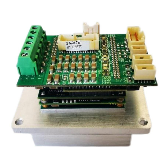
Catalog Number This guide is delivered subject to the following conditions and restrictions: This guide contains proprietary information belonging to Elmo Motion Control Ltd. Such information is supplied solely for the purpose of assisting users of the Gold Mol Twitter servo drive in its installation. - Page 3 Catalog Number G–MOLTWI A xx /100 E E O T T = 接线端子 - 推荐 10A 以内采用, 大于 10 采用焊线孔 GOLD LINE O = 24V IO, PNP 型,DO 输出 2A, STO 板子内部实现 T = 5V IO, PNP 型,DO 输出 0.2A Monotion customizes -STO 板子内部实现...
-
Page 4: Table Of Contents
Table of Contents Chapter 1 :This Installation Guide ...................... 1 Chapter 2 :Safety Information ......................1 2.1 Warnings ..........................2 2.2 Cautions ..........................2 2.3 Warranty Information ......................2 Chapter 3 :Product Description ......................3 Chapter 4 :Technical Information ....................... 4 4.1 Physical Specifications ...................... - Page 5 8.3.1.1 Incremental Encoder ..................31 8.3.1.2 Absolute Serial Encoder ................31 8.3.1.3 Hall Sensors ....................32 8.3.2 Port B ........................33 8.3.2.1 Incremental Encoder ..................33 8.3.2.2 Interpolated Analog Encoder ............... 33 8.3.2.3 Resolver ......................34 8.3.2.4 Port C–Emulated Encoder Output (J5) ............34 8.4 J7 I/O and STO Connector ....................35 8.4.1 Digital Inputs ......................36 8.4.1.1 Source PLC Voltage Level Digital Input ............36...
-
Page 6: Chapter 1 :This Installation Guide
To avoid any potential hazards that may cause severe personal injury or damage to the product during operation, keep all covers and cabinet doors shut. The following safety symbols are used in this and all Elmo Motion Control manuals: Warning: This information is needed to avoid a safety hazard, which might cause bodily injury or death as a result of incorrect operation. -
Page 7: Warnings
All Elmo drives are warranted for a period of 12 months from the date of shipment. No other warranties, expressed or implied — and including a warranty of merchantability and fitness for a particular purpose —... -
Page 8: Chapter 3 :Product Description
The Gold Mol Twitterdrive is easily set up and tuned using the Elmo Application Studio (EASII) software tools. As part of the Gold product line, it is fully programmable with the Elmo motion control languages. For more information about software tools refer to the Elmo Application Studio (EASII) User Guide. -
Page 9: Chapter 4 :Technical Information
Gold Mol Twitter Installation Guide MAN-G-MOLTWI Chapter 4 :Technical Information Note: It should be noted that for all models, the Max Output current is guaranteed for THeat-Sink <85°C 4.1 Physical Specifications Throughout the feature column, for each product, there is a blue hyperlink to the relevant section in the Dimensions chapter. -
Page 10: 100V Models Technical Data
Gold Mol Twitter Installation Guide MAN-G-MOLTWI 4.2 100V Models Technical Data Feature Units 1/100 3/100 6/100 10/100 15/100 25/100 Minimum supply voltage Nominal supply voltage Maximum supply voltage Maximum continuous power output 1125 2000 Efficiency at rated power (at nominal >99 conditions) Maximum output voltage... -
Page 11: R Type Technical Data
Gold Mol Twitter Installation Guide MAN-G-MOLTWI 4.4 R Type Technical Data Feature Units R80/80 R50/100 R70/100 Minimum supply voltage Nominal supply voltage Maximum supply voltage Maximum continuous Electrical power output Efficiency at rated power (at nominal conditions) > 99 Maximum output voltage Up to 96% of DC bus voltage Amplitude sinusoidal/DC continuous current Sinusoidal continuous RMS current limit (Ic) -
Page 12: Product Features
Gold Mol Twitter Installation Guide MAN-G-MOLTWI 4.6 Product Features Main Feature Details Presence / No. +5V Logic, Opto isolated from the Control section, or √ PLC Source, Opto isolated from the Control section √ Digital Input +5V Logic, Opto isolated from the Control section or PLC Source, Opto isolated from the Control section or PLC Sink Opto isolated from the Control section Digital Output... -
Page 13: Environmental Conditions
Gold Mol Twitter Installation Guide MAN-G-MOLTWI 4.7 Environmental Conditions You can guarantee the safe operation of the Gold Mol Twitter by ensuring that it is installed in an appropriate environment. The following table describes the certified environmental conditions for STO of the Gold series servo drives. Warning: During operation the Gold Mol Twitter becomes hot to the touch (the heatsink and wires may heat up to 92 °C). -
Page 14: Chapter 5 :Standards And Certifications
Gold Mol Twitter Installation Guide MAN-G-MOLTWI Chapter 5 :Standards and Certifications 5.1 Functional Safety Standard Item IEC 61800-5-2:2017 Adjustable speed electrical power drive systems – Safety requirements – Functional ENISO 13849-1:2015 Safety of machinery — Safety-related parts of control systems. EN 61508-1:2010 Functional safety of electrical/electronic/ programmable electronic safety-related systems EN 61508-2:2010... -
Page 15: Ce Declaration
Gold Mol Twitter Installation Guide MAN-G-MOLTWI 5.5 CE Declaration Refer to the complete EC Declaration of Conformity available on the internet at: https://www.elmomc.com/wp-content/uploads/dlm_uploads/2018/05/Gold-Line-CE- Declaration-of-Conformity.pdf. 5.6 Dual Use No export license is required for the Gold Line products signified with the suffix Q in the Part Number. -
Page 16: Chapter 6 :Installation
The Gold Mol Twitter servo drive The Elmo Application Studio (EASII) software and software manual The Gold Mol Twitter is shipped in a cardboard box with Styrofoam protection. To unpack the Gold Mol Twitter : Carefully remove the servo drive from the box and the Styrofoam. -
Page 17: Mounting The Optional Accessories Heat Sinks
Gold Mol Twitter Installation Guide MAN-G-MOLTWI 6.2 Mounting the Optional Accessories Heat Sinks There are two optional heat sinks, available as accessory kits : Flat Heat Sink (P/N:FIN-TWI) Fins Heat Sink (P/N:Fin-GSOLTWI) The optional heat sink must be screwed to the lower surface of the Gold Mol Twitter . |Installation|www.elmomc.com —... - Page 18 Gold Mol Twitter Installation Guide MAN-G-MOLTWI To mount the accessory heatsink Mount the heat sink under the base of the Gold Mol Twitter . Place the Thermal foil (enclosed in the heat sink accessories kit) between the lower surface of the servo drive, and the upper surface of the heatsink. Use four M2 screws (enclosed in the heat sink accessories kit) to secure the heatsink under the servo drive.
-
Page 19: Mounting Gold Mol Twitter To An External Heatsink
Gold Mol Twitter Installation Guide MAN-G-MOLTWI 6.3 Mounting Gold Mol Twitter to an External Heatsink The selected heat sink must be screwed to the lower surface of the Gold Mol Twitter . To mount the Gold Mol Twitter to an external heat sink: Mount the heat sink under the base of the Gold Mol Twitter . -
Page 20: The Gold Mol Twitter Connection Diagrams
Gold Mol Twitter Installation Guide MAN-G-MOLTWI 6.4 The Gold Mol Twitter Connection Diagrams 6.4.1 EtherCAT with Mini USB Connector Connection Diagram Gold Mol Twitter Figure 4: The Gold Mol Twitter EtherCAT Connection Diagram |Installation|www.elmomc.com — 15 —... -
Page 21: Can Connection Diagram
Gold Mol Twitter Installation Guide MAN-G-MOLTWI 6.4.2 CAN Connection Diagram Gold Mol Twitter Figure 5: The Gold Mol Twitter CAN Connection Diagram J13(4pin) Gold Mol Twitter |Installation|www.elmomc.com — 16 —... -
Page 22: Chapter 7 :Wiring
Gold Mol Twitter Installation Guide MAN-G-MOLTWI Chapter 7 :Wiring 7.1 Wiring Legend The following table legend describes the wiring symbols detailed in all installation guides. Wiring Symbol Description Earth connection (PE) Earth Connection Common at the Controller Shielded cable with drain wire. The drain wire is a non-insulated wire that is in direct contact with the braid (shielding). -
Page 23: Mating Connectors
Gold Mol Twitter Installation Guide MAN-G-MOLTWI 7.2 Mating Connectors The Gold Mol Twitter has six connectors: Connector Mating Connector Type Mating Crimping Pins Power PHEONIX 3.5 mm pitch terminal 6-pin plug J4 VL Ports Connector MOLEX 2 mm Pitch MOLEX 1.00mm crimp terminal Molex 35507-0200 Molex 50212-8000 J5 Feedback Ports Connector... -
Page 24: Logic And Control Cabling And Wiring
Wires can always be used, no need for twisting, no need for shielding. 7.3.3 J8, J9 EtherCAT or CAN Communication Always use CAT5e cables (see Elmo’s Gold Mol Twitter Cable Kit (CBL-GMOLTWISEKIT)). 7.3.4 COMRET to PE Connection Gold Mol Twitte... -
Page 25: Wiring The Female Connectors
Gold Mol Twitter Installation Guide MAN-G-MOLTWI 7.4 Wiring the Female Connectors Figure 8: Inserting a pin to the Female Connector To insert a pin to the female connectors of J5, J7, J13, and J8, J9 do the following: Select the relevantly colored wire to insert to a specific rectangular compartment on the female connector. -
Page 26: Chapter 8 :Connections
Gold Mol Twitter Installation Guide MAN-G-MOLTWI Chapter 8 :Connections 8.1 Main, Control, and Motor Power This section describes the Main and Control supplies, and Motor Power connections. There are two optional Motor and Main Power interfaces: The current carrying capacity of the MOL board wires is up to 80A ... -
Page 27: Motor Power Connections
Connect the appropriate wire from the Motor Power cables to the M1, M2, M3, and PE terminals on the Gold Mol Twitter . The phase connection is arbitrary as Elmo Application Studio (EAS II) will establish the proper commutation automatically during setup. When tuning a number of drives, you can copy the setup file to the other drives and thus avoid tuning each drive separately. -
Page 28: Main Power Wires & Connector
Gold Mol Twitter Installation Guide MAN-G-MOLTWI 8.1.2 Main Power Wires & Connector This section describes the Main Power and the Control supply connector. 8.1.2.1 Main Power The isolated DC power source is not included with the Gold Mol Twitter . Function Cable Pin Positions... -
Page 29: Wiring Technical Details
Gold Mol Twitter Installation Guide MAN-G-MOLTWI Connect the PE to the closest earth connection near the power supply. Connect the PR to the closest earth connection near the power supply. Before applying power, first verify the polarity of the connection. 8.1.2.2 Wiring Technical Details The six 14-AWG, silicon insulated, 300mm length colored high quality, power connection wires are rated to operate up to 200°C:... -
Page 30: Control Supply (J4)
Gold Mol Twitter Installation Guide MAN-G-MOLTWI 8.1.3 Control Supply (J4) Connect the VL+ and VL- pins on the Gold Mol Twitter in the manner described in the table and drawing below. Signal Function Control Supply Input Control Supply Return Pin Positions VL+(24V+) VL- (24V- ) Table 7: Control Supply Pins... -
Page 31: Control Supply Connections For Power Supply
Gold Mol Twitter Installation Guide MAN-G-MOLTWI 8.1.4 Control Supply Connections for Power Supply 8.1.4.1 Dual Power Supply Whenever the VP+ is >95VDC, a separate supply for the Logic is required. Both the Power and Logic supplies are required to be isolated-from-the-mains: A battery or main DC power source rectified from the Mains, according to specification ... -
Page 32: Single Power Supply (Vp+ < 95Vdc)
Gold Mol Twitter Installation Guide MAN-G-MOLTWI Gold Mol Twitter Gold Mol Twitter Figure 17: Separate VP and VL Power Supplies Connection Diagram - Alternative The (-) of the control power supply is connected to the VL- of the Gold Mol Twitter (Figure 17). 8.1.4.2 Single Power Supply (VP+ <... -
Page 33: Drive Status Indicator
Gold Mol Twitter Installation Guide MAN-G-MOLTWI 8.2 Drive Status Indicator Figure 20 shows the position of the red/green dual LED, which is used for immediate indication of the Initiation and Working states. LED1 is the drive error indicator and is red LED2 is the normal indicator of the drive, which is steady green -CAN version:... -
Page 34: Feedback Connector
Gold Mol Twitter Installation Guide MAN-G-MOLTWI 8.3 Feedback Connector Feedback Connector The following table describes the J5 Feedback connections to the 2 x 15 pins female connector. Pin J5 Signal Function PortA_ENC_A+ / ABS_CLK+ Channel A+ / Abs encoder clock + PortB_ENC_A- Port B Channel A- PortA_ENC_A- / ABS_CLK-... - Page 35 Common return COMRET Common return COMRET Table 8: Connector J5 – Feedback For longer distances than 1.0 m and/or high EMI environment, shielded and twisted wires should be used. Drain wires should be connected to Elmo COMRET. |Connections|www.elmomc.com — 30 —...
-
Page 36: Port A
Gold Mol Twitter Installation Guide MAN-G-MOLTWI 8.3.1 Port A 8.3.1.1 Incremental Encoder Gold Mol Twitter Gold Mol Twitter Figure 22: Port A Incremental Encoder Input – Recommended Connection Diagram 8.3.1.2 Absolute Serial Encoder Gold Mol Twitter Gold Mol Twitter Gold Mol Twitter Gold Mol Twitter Figure 23: Absolute Serial Encoder –... -
Page 37: Hall Sensors
Gold Mol Twitter Installation Guide MAN-G-MOLTWI Gold Mol Twitter Gold Mol Twitter Figure 24: Absolute Serial Encoder – Recommended Connection Diagram for Sensors Supporting Data Line Only (NRZ types, e.g., Panasonic / Mitutoyo / etc.) 8.3.1.3 Hall Sensors Gold Mol Twitter Gold Mol Twitter Figure 25: Hall Sensors Connection Diagram |Connections|www.elmomc.com... -
Page 38: Port B
Gold Mol Twitter Installation Guide MAN-G-MOLTWI 8.3.2 Port B 8.3.2.1 Incremental Encoder Gold Mol Twitter Figure 26: Port B Incremental Encoder Input – Recommended Connection Diagram 8.3.2.2 Interpolated Analog Encoder Gold Mol Twitter Figure 27: Port B - Interpolated Analog Encoder Connection Diagram |Connections|www.elmomc.com —... -
Page 39: Resolver
Gold Mol Twitter Installation Guide MAN-G-MOLTWI 8.3.2.3 Resolver Gold Mol Twitter Figure 28: Port B – Resolver Connection Diagram 8.3.2.4 Port C–Emulated Encoder Output (J5) Gold Mol Twitter Figure 29: Emulated Encoder Differential Output – Recommended Connection Diagram |Connections|www.elmomc.com — 34 —... -
Page 40: J7 I/O And Sto Connector
Gold Mol Twitter Installation Guide MAN-G-MOLTWI 8.4 J7 I/O and STO Connector J7 I/O and STO Communication Connector Pin J7 Signal Function IN-RET return INI-RET return High speed programmable digital input 6 (opto isolated from control COMRET) High speed programmable digital input 5 (opto isolated from control COMRET) High speed programmable digital input 4 (opto isolated from control COMRET) High speed programmable digital input 3 (opto isolated from control COMRET) 13&15 OUT1... -
Page 41: Digital Inputs
Gold Mol Twitter Installation Guide MAN-G-MOLTWI 8.4.1 Digital Inputs If you use digital output, you need to connect VL+ (24VDC). 8.4.1.1 Source PLC Voltage Level Digital Input The following are the connection diagram of Digital inputs: Feature Details Isolated PLC source Standard Conforming to IEC 61131-2 Iin = (Vin-7.4)/4.99 Kohm Iin = 920 uA @ Vin = 12 V... - Page 42 Gold Mol Twitter Installation Guide MAN-G-MOLTWI Figure 32: Digital Input Connection Diagram Example – Source PLC Option |Connections|www.elmomc.com — 37 —...
-
Page 43: Source 5V Logic Level Digital Input
Gold Mol Twitter Installation Guide MAN-G-MOLTWI 8.4.1.2 Source 5V Logic Level Digital Input Feature Details Type of input Optically isolated Input current for all inputs Iin = 3.8 mA @ Vin = 5 V High-level input voltage 3.0 V < Vin < 10 V, 5 V typical Low-level input voltage 0 V <... - Page 44 Gold Mol Twitter Installation Guide MAN-G-MOLTWI Gold Mol Twitter Figure 36: Digital Input Source 5V Logic Mode Connection Diagram |Connections|www.elmomc.com — 39 —...
-
Page 45: Digital Outputs
Gold Mol Twitter Installation Guide MAN-G-MOLTWI 8.4.2 Digital Outputs 8.4.2.1 Source PLC Voltage Level Digital Output Feature Details Type of output Optically isolated PLC source Supply output (VDD) 12V to 30V (typically 24V) Max. output current Iout (max) (Vout = Iout (max) ≤... - Page 46 Gold Mol Twitter Installation Guide MAN-G-MOLTWI 13&15 17&19 14&16/18&20 Gold Mol Twitter Figure 38: Digital Output Connection Diagram Example – Source PLC Option |Connections|www.elmomc.com — 41 —...
-
Page 47: Digital Outputs Source 5V Logic Mode
Gold Mol Twitter Installation Guide MAN-G-MOLTWI 8.4.2.2 Digital Outputs Source 5V Logic Mode Feature Details Type of output Optically isolated 5V Logic source Supply output (VDD) < 30 V (Typically 5 V) Max. output current Iout (max) (Vout = Iout (max) ≤ 30 mA High) Collector Emitter saturation voltage Ton (Time from low to high) If Vdd= 5V... - Page 48 Gold Mol Twitter Installation Guide MAN-G-MOLTWI 13&15 17&19 14&16/18&20 Gold Mol Twitter Figure 42: Digital Output Connection Diagram Example – Source 5V Logic Option |Connections|www.elmomc.com — 43 —...
-
Page 49: Sto (Safe Torque Off)
Gold Mol Twitter Installation Guide MAN-G-MOLTWI 8.4.3 STO (Safe Torque Off) Gold Mol Twitter Figure 43: STO Input Connection – 5V Logic Gold Mol Twitter Figure 44: STO Input Connection – PLC (24V Logic) 8.4.4 Analog Input Gold Mol Twitter Figure 45: Analog Input |Connections|www.elmomc.com —... -
Page 50: Communication Connector
Gold Mol Twitter Installation Guide MAN-G-MOLTWI 8.5 Communication Connector 8.5.1 Standard RS-232 Pin J13 Signal Function COMRET Common return RS-232_RX RS-232 Receive RS-232_TX RS-232 Transmit COMRET Common return Gold Mol Twitter Figure 46: Standard RS-232 Connection Diagram 8.5.2 USB Communication (Only for EtherCAT version) Pin J13 Signal Function... -
Page 51: Ethercat Communications Version
Gold Mol Twitter Installation Guide MAN-G-MOLTWI 8.6 EtherCAT Communications Version Fieldbus communications are industrial network protocols for real-time distributed control that allows connection of servo drives. The Gold Mol Twitter supports the following EtherCAT fieldbus type industrial network protocol: Fieldbus Type Product Number EtherCAT G-MOLTWIXX/YYYEXXX... -
Page 52: Ethercat Out Connector (J8)
Gold Mol Twitter Installation Guide MAN-G-MOLTWI 8.6.2 EtherCAT OUT Connector (J8) Pin (J8) Signal Function EtherCAT_OUT_TX+ EtherCAT out transmit + EtherCAT_OUT_TX- EtherCAT out transmit - EtherCAT_OUT_RX+ EtherCAT out receive + EtherCAT_OUT_RX- EtherCAT out receive - COMRET Shield drain wire Pin Positions Cable Connector Ethernet Cable Connector Table 12: EtherCAT OUT Pin Assignments... -
Page 53: Ethercat Schematic Connections
Gold Mol Twitter Installation Guide MAN-G-MOLTWI 8.6.3 EtherCAT Schematic Connections Note: The EtherCAT IN port can be configured to an Ethernet Port. 8.6.3.1 EtherCAT Communication This section only describes the EtherCAT communication, and the pinout drawing of the connector. When the EtherCAT is connected and the FoE is in operation, the USB cable connection must be disconnected. -
Page 54: Can Communications Version
Gold Mol Twitter Installation Guide MAN-G-MOLTWI 8.7 CAN Communications Version Fieldbus communications are industrial network protocols for real-time distributed control that allows connection of servo drives. The Gold Mol Twitter supports the following CAN fieldbus type industrial network protocol: Fieldbus Type Product Number G-MOLTWIXX/YYYSXXX 8.7.1 CAN IN Connector (J9) -
Page 55: Can Out Connector (J8)
Gold Mol Twitter Installation Guide MAN-G-MOLTWI 8.7. 2 CAN OUT Connector (J8) Pin (J8) Signal Function CAN_L CAN_L bus line (dominant low) CAN_RET CAN Return CAN_H CAN_H bus line (dominant high) COMRET Shield drain wire Pin Positions Cable Connector CAN Cable Connector Table 14: CAN OUT Connectors Pin Assignments Note: Always use CAT5e cables. -
Page 56: Can Schematic Connections
Gold Mol Twitter Installation Guide MAN-G-MOLTWI 8.7.3 CAN Schematic Connections 8.7.3.1 Interface The Gold Mol Twitter includes the CAN transceiver, common mode choke, and a CAN Bus Protector against ESD and other harmful transient voltage events. The following signals describe how to connect CAN to the external connector. Gold Mol Twitter Figure 52: CAN Interface Gold Mol Twitter... - Page 57 Gold Mol Twitter Installation Guide MAN-G-MOLTWI Caution: When installing CAN communication, ensure that each servo drive is allocated a unique ID. Otherwise, the CAN network may “hang”. Note: Daisy chain topology can also be accomplished using J18. Note: Always use CAT5e cables. |Connections|www.elmomc.com —...
-
Page 58: Chapter 9 :Powering Up
After the Gold Mol Twitter has been connected and mounted, the system must be set up and initialized. This is accomplished using the EASII, Elmo’s Windows-based software application. Install the application and then perform setup and initialization according to the directions in the EASII User Manual. - Page 59 Gold Mol Twitter Installation Guide MAN-G-MOLTWI Up|www.elmomc.com |Powering — 54 —...
- Page 60 Gold Mol Twitter Installation Guide MAN-G-MOLTWI Up|www.elmomc.com |Powering — 55 —...
-
Page 61: How To Use The Chart
Gold Mol Twitter Installation Guide MAN-G-MOLTWI 9.2.2 How to Use the Chart The charts above are based upon the theoretical worst-case scenario. The actual test results display a 20% -30% lower power dissipation. The above charts indicate the net power conversion losses and exclude the control losses. To determine if your application heat dissipation requires a heat sink: Determine the power dissipation according to the "continuous current"... -
Page 62: Chapter 10 :Accessories
Gold Mol Twitter Installation Guide MAN-G-MOLTWI Chapter 10 :Accessories The following describes the accessory kits available for the Gold Mol Twitter . Part Number Description CBL-GMOLTWIEEKIT Kit cable for EtherCAT model CBL-GMOLTWISEKIT Kit cable for CAN model G-TWIHSFLAT01 Flat Heat-Sink Kit G-TWIHSFINS01 FINs Heat-Sink Kit 10.1 Mounting the Optional Accessories Heat Sink... -
Page 63: Accessories Heat Sink Dimensions
Gold Mol Twitter Installation Guide MAN-G-MOLTWI 10.2. Accessories Heat Sink Dimensions Figure 72: G-Molo Twitter – Flat Heat Sink (P/N FIN-TWI) Dimensions |www.elmomc.com Cable Kit — 58 —... - Page 64 Gold Mol Twitter Installation Guide MAN-G-MOLTWI Figure 73: G-Solo Twitter – Fins Heat Sink (P/N G-TWIHSFINS01) |www.elmomc.com Cable Kit — 59 —...
-
Page 65: Chapter 11:Gold Mol Twi Cable Kit
Gold Mol Twitter Installation Guide MAN-G-MOLTWI Chapter 11:Gold MOL TWI Cable Kit CBL-GMOLTWISEKIT CBL-GMOLTWIEEKIT 11.1 G-MOL TWI Connectors The table below presents the connector panel of the Gold MOL TWIe drive and specifies the cable connectors. Port Type Connector Manufacturer and Pins Part Number 5.08 mm pitch... -
Page 66: Main Feedback Cable (Cbl-Gmoltwifbk1M)
Gold Mol Twitter Installation Guide MAN-G-MOLTWI 11.2 Main Feedback Cable (CBL-GMOLTWIFBK1M) The Feedback Cable is a 30-AWG Teflon isolation set of wires of length 1m. It is connected using a 1.0 mm female housing 2x15 pins Molex connector and 1.0 mm single-pin crimp terminal at one end to the J5 connector on the Gold Mol Twitter, with the cable open at the other end so that it can be connected to the relevant controller interface connectors. -
Page 67: Sto, And I/ O Cable (Cbl-Gmolio1,G-Molsto1T)
Gold Mol Twitter Installation Guide MAN-G-MOLTWI 11.3 STO, and I/ O Cable (CBL-GMOLIO1,G-MOLSTO1T) The STO, and I/O cable is a 30-AWG Teflon isolation set of wires of length 1m. It is connected using a 1.0 mm female housing 2x10 pins Molex connector and 1.0 mm single-pin crimp terminal at one end to the J7 connector on the Gold Mol Twitter, with the cable open at the other end so that it can be connected to the relevant controller interface connectors.The general pinout of the STO, and I/O cable is as follows:... -
Page 68: Can Communication Cable (Cbl-Gmoltwican1Mr)
Gold Mol Twitter Installation Guide MAN-G-MOLTWI 11.4 CAN Communication Cable (CBL-GMOLTWICAN1MR) The standard CAN Ports Communication cable is supplied in 1.0 m lengths. The CAN port cable consists of a double-pair 30-AWG drain and braid cable. At one end of the cable is a wire to board 5-pin, 1 mm pitch, female Molex connector, and at the other end an RJ-45 standard communication connector.The general pinout of the CAN ports cable is as follows: J8, J9 Pins... -
Page 69: Ethercat Communication Cable (Cbl-Gmoltwieth1Mr)
Gold Mol Twitter Installation Guide MAN-G-MOLTWI 11.5 EtherCAT Communication Cable (CBL-GMOLTWIETH1MR) The standard EtherCAT Ports Communication cable is supplied in 1.0 m lengths. The EtherCAT ports cable consists of a double-pair 30-AWG drain and braid cable. At one end of the cable is a wire to board 5-pin, 1 mm pitch, female Molex connector, and at the other end an RJ-45 standard communication connector.The general pinout of the EtherCAT ports cable for either J8 or J9 connection is as follows:... -
Page 70: Ethercat/ Can Link Cable
Gold Mol Twitter Installation Guide MAN-G-MOLTWI 11.6 EtherCAT/ CAN LINK Cable The EtherCAT/CAN LINK Cable is a double-pair 30-AWG drain and braid cable of 0.3m. It is connected at both ends with wire-to-board 5 Pins 1 mm Pitch female Molex connectors. The general pinout of the EtherCAT/CAN LINK Cable as a daisy chain is as follows: CBL-GMOLTWIETH0.3M Molex 1... -
Page 71: Can Terminator Cable (Cbl-Gmoltwicant)
Gold Mol Twitter Installation Guide MAN-G-MOLTWI 11.7 CAN Terminator Cable (CBL-GMOLTWICANT) The CAN Terminator Cable is a 120Ω resistor as termination. It is connected at both ends with wire-to-board 5 Pins 1 mm Pitch female Molex connector. The general pinout of the CAN Terminator Cable is as follows: Molex 1 COLOR Function... - Page 72 Gold Mol Twitter Installation Guide MAN-G-MOLTWI |www.elmomc.com Cable Kit...
Need help?
Do you have a question about the Gold Mol Twitter Digital and is the answer not in the manual?
Questions and answers