Advertisement
Quick Links
Advertisement

Subscribe to Our Youtube Channel
Related Manuals for Elmo Gold Bell


Summary of Contents for Elmo Gold Bell
- Page 1 Gold Bell Digital Servo Drive Installation Guide April 2018 (Ver. 1.200) www.elmomc.com...
- Page 2 • This guide contains proprietary information belonging to Elmo Motion Control Ltd. Such information is supplied solely for the purpose of assisting users of the Gold Bell servo drive in its installation. The text and graphics included in this manual are for the purpose of illustration and reference •...
- Page 3 Unpacking the Drive Components ................13 Chapter 6: Mounting the Gold Bell .................. 14 Chapter 7: Integrating the Gold Bell on a PCB ..............15 Power Returns (PR) ....................... 15 COMRET ........................15 Earth Connection (PE) ....................15 Power Return (PR), Common Return (COMRET) and Earth Connections (PE) ..... 16 Power Conductors PCB layout ..................
- Page 4 Table of Contents MAN-G-BELIG (Ver. 1.200) 9.5.4.1 Single Power Supply ..............28 9.5.4.2 Shared Supply ................30 Connector J2 - Feedback, Analog Inputs, RS-232, USB, EtherCAT, Ethernet, and CAN 31 9.6.1 Feedback Port A .................... 34 9.6.1.1 Incremental Encoder ..............34 9.6.1.2 Hall Sensors ..................
- Page 5 Chapter 2: Safety I nform ation In order to achieve the optimum, safe operation of the Gold Bell, it is imperative that you implement the safety procedures included in this installation guide. This information is provided to protect you and to keep your work area safe when operating the Gold Bell and accompanying equipment.
- Page 6 Make sure that the Safe Torque Off is operational 2.3 CE Marking Conformance The Gold Bell is intended for incorporation in a machine or end product. The actual end product must comply with all safety aspects of the relevant requirements of the European Safety of...
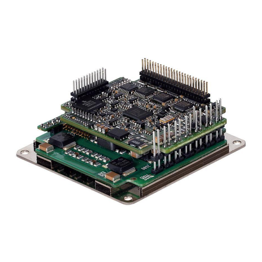
- Page 7 ) package (55 x 59 x 15 mm or 2.17” x 2.32” x 0.6”). The Gold Bell is designed to be mounted on a PCB by soldering its pins directly to the PCB. This advanced, high power density servo drive provides top performance, advanced networking and built-in safety, as well as a fully featured motion controller and local intelligence.
- Page 8 Table 1: Technical Data Note on current ratings: The current ratings of the Gold Bell are given in units of DC amperes (ratings that are used for trapezoidal commutation or DC motors). The RMS (sinusoidal commutation) value is the DC value divided by 1.41.
- Page 9 Gold Bell Installation Guide MAN-G-BELIG (Ver. 1.200) Elmo offers a 200 VDC maximum output rating selection of Gold Bell, according to the following technical data: Feature Units 3/200 6/200 9/200 Minimum supply voltage Nominal supply voltage Maximum supply voltage Maximum continuous power output...
- Page 10 Gold Bell Installation Guide MAN-G-BELIG (Ver. 1.200) 4.2.2 Product Features Main Feature Details Presence / No. √ Digital Input Option Open Collector-emitter (isolated) Digital Output Option TTL 3.3V(Non Isolation) Differential ±10V Analog Input Single Ended √ Standard Port A, B, & C Feedback √...
- Page 11 Gold Bell Installation Guide MAN-G-BELIG (Ver. 1.200) 4.2.3 Environmental Conditions You can guarantee the safe operation of the Gold Bell by ensuring that it is installed in an appropriate environment. Feature Details Operating ambient temperature 0 °C to 40 °C (32 °F to 104 °F)
- Page 12 Gold Bell Installation Guide MAN-G-BELIG (Ver. 1.200) 4.2.4 Gold Line Standards The following table describes the Main Standards of the Gold Bell servo drive. For further details refer to Chapter 17 in the MAN-G-Board Level Modules Hardware Manual. Main Standards Item The related standards below apply to the performance of the servo drives as stated in the environmental conditions in section 4.2.3 Environmental Conditions above.
- Page 13 The Gold Bell must be installed in a suitable environment and properly connected to its voltage supplies and the motor. 5.1 Unpacking the Drive Components Before you begin working with the Gold Bell, verify that you have all of its components, as follows: The Gold Bell servo drive •...
- Page 14 The Gold Bell was designed for mounting on a printed circuit board (PCB) via 1.27 mm pitch 0.41 mm square pins and 2 mm pitch 0.51 mm square pins. When integrating the Gold Bell into a device, be sure to leave about 1 cm (0.4") outward from the heat sink to enable free air convection around the drive.
- Page 15 I ntegrating the Gold Bell on a PCB The Gold Bell is designed to be mounted on a PCB by soldering its pins directly to the PCB. Refer to Chapter 5 in the MAN-G-Board Level Modules Hardware Manual and the drawings in the Gold Line Whistle Design Guide MAN-G-WHIIDG for further information.
- Page 16 100V models, between PE to PR. However, the connections between PE to PR and the COMRET are essential for the safe operation of the servo drive. Therefore the following topology must be used: Figure 2: Gold Bell Earth Connections The connections to PE are essential, but must be done externally to the integration board.
- Page 17 Control and Communication Zone This area of the PCB is dedicated to Control low level signals Figure 3: Gold Bell Power Conductors PCB layout For more details, refer to the section 5.4 in the MAN-G-Board Level Modules Hardware Manual. |Connector J2 |www.elmomc.com...
- Page 18 Gold Bell Installation Guide MAN-G-BELIG (Ver. 1.200) Chapter 8: The Gold Bell Connection Diagram Figure 4: The Gold Bell Connection Diagram |Connector J2 |www.elmomc.com Table of Contents...
- Page 19 Gold Bell Installation Guide MAN-G-BELIG (Ver. 1.200) Chapter 9: PCB Connections 9.1 Wiring legend The following table legend describes the wiring symbols detailed in all installation guides. All the wiring diagrams show wiring for D-TYPE connectors. Wiring Symbol Description Earth connection (PE)
- Page 20 Gold Bell Installation Guide MAN-G-BELIG (Ver. 1.200) Wiring Symbol Description Encoder Earthing. The cable`s shield is connected to the chassis (PE) in the connector. Earthing the Encoder and connecting the Earth (PE) to the drive COMRET is mandatory to insure reliable...
- Page 21 Gold Bell Installation Guide MAN-G-BELIG (Ver. 1.200) 9.2 Connector Types The Gold Bell has nine connectors. 9.2.1 Connector Types Port Pins Type Function 2x24 1.27 mm pitch, Feedbacks, Digital Halls, Analog Inputs, Communications 0.41 mm sq 2x12 I/O, LEDs, STO...
- Page 22 Gold Bell Installation Guide MAN-G-BELIG (Ver. 1.200) 9.3 Drive Status Indicator For details of the Drive Status Indicator wiring, refer to the Chapter 7 in the MAN-G-Board Level Modules Hardware Manual. 9.4 Motor Power Connector Pinouts For full details see Chapter 8 in the MAN-G-Board Level Modules Hardware Manual.
- Page 23 Gold Bell Installation Guide MAN-G-BELIG (Ver. 1.200) Figure 5: Brushless Motor Power Connection Diagram Figure 6: DC Brushed Motor Power Connection Diagram |Connector J2 |www.elmomc.com Table of Contents...
- Page 24 Gold Bell Installation Guide MAN-G-BELIG (Ver. 1.200) Figure 7: Stepper Motor Power Connection Diagram |Connector J2 |www.elmomc.com Table of Contents...
- Page 25 Gold Bell Installation Guide MAN-G-BELIG (Ver. 1.200) 9.5 Main Power and Control Connector There are two power ratings for the Gold Bell: • 100V for is 12 to 95 VDC • 200V for the 12 to 195 VDC For power rating 200V Two DC power sources are required, a DC power source of 12 to 195V isolated from the Mains, and a control supply 12 to 95V (isolated from the Mains) for the logic.
- Page 26 Gold Bell Installation Guide MAN-G-BELIG (Ver. 1.200) 9.5.2 Control Supply The Control supply is required for the 200V power rating, and can be added for the 100V power Note: rating. The source of the Control Supply must be from the Mains.
- Page 27 Gold Bell Installation Guide MAN-G-BELIG (Ver. 1.200) 9.5.3 Power Supply for the Power Rating 200 V For Power Rating 200 V, two DC power sources are required, a main power 12 to 195V DC power source isolated from the Mains, and a control power supply 12 to 95V (isolated from the Mains) for the logic.
- Page 28 Only one power supply is required for the main and control power. It is strongly recommended to add a filter on the VL+ Input Pin at the Gold Bell, in order to avoid interference from the power stage e.g. noises. The following figure describes the filter recommended.
- Page 29 Gold Bell Installation Guide MAN-G-BELIG (Ver. 1.200) Figure 10: Single Power Supply Connection Diagram with VL+ connected externally Note: Make sure to connect the PR to the closest earth connection near the power supply. |Connector J2 |www.elmomc.com Table of Contents...
- Page 30 Gold Bell Installation Guide MAN-G-BELIG (Ver. 1.200) 9.5.4.2 Shared Supply A single DC Power Supply can supply the power for logic as well as the main power. If separation between the main DC power source and a control supply is required, then a control supply (isolated from the Mains) can be connected by implementing “diode coupling"...
- Page 31 The J2 Connector exports all supported communication links. However, note that CAN and EtherCAT are not available in the same version of the Gold Bell and are thus not operational simultaneously. See the part number diagram in Section 5.1 above for the different Gold Bell configurations.
- Page 32 Gold Bell Installation Guide MAN-G-BELIG (Ver. 1.200) Pin (J2) Signal Function PortC_ENCO_INDEX- Port C - index complement output PortA_ENC_INDEX- Port A - index complement PortC_ENCO_INDEX+ Port C - index output PortB_ENC_A+/SIN+ Port B - channel A/SIN+ Hall sensor C input...
- Page 33 Gold Bell Installation Guide MAN-G-BELIG (Ver. 1.200) Pin (J2) Signal Function EtherCAT: PHY_OUT_TX- EtherCAT Out transmit complement CAN: Reserved Reserved PHY_IN_LINK_ACT EtherCAT In active LED EtherCAT: PHY_OUT_LINK_ACT EtherCAT Out active LED CAN: CAN_L CAN_L BUS Line(dominant low) PHY_IN_SPEED EtherCAT In Speed LED...
- Page 34 Gold Bell Installation Guide MAN-G-BELIG (Ver. 1.200) 9.6.1 Feedback Port A Port A supports the following sensor inputs: Digital Hall sensors • Incremental encoder or absolute serial encoder, depending on the specific model • Differential pulse-width modulation (PWM) signal input can be connected to port A •...
- Page 35 Gold Bell Installation Guide MAN-G-BELIG (Ver. 1.200) 9.6.1.2 Hall Sensors Figure 13: Hall Sensors Connection Diagram |Connector J2 |www.elmomc.com Table of Contents...
- Page 36 Gold Bell Installation Guide MAN-G-BELIG (Ver. 1.200) 9.6.1.3 Absolute Serial Encoder The following Absolute Encoder are supported: • Endat 2.2 Biss C and Biss B • • Pansonic Tamagawa • • • Sanyo Danki Hiperface • The following is the diagram connection of the Endat, Biss, SSI: Figure 14: Absolute Serial Encoder –...
- Page 37 Gold Bell Installation Guide MAN-G-BELIG (Ver. 1.200) The following is the diagram connection of the Pansonic, Tamgawai, Sanyo-Danki: Figure 15: Absolute Serial Encoder – Recommended Connection Diagram for Pansonic, Tamgawai, Sanyo-Danki |Connector J2 |www.elmomc.com Table of Contents...
- Page 38 Gold Bell Installation Guide MAN-G-BELIG (Ver. 1.200) 9.6.1.4 Hiperface The following figure describes the connection diagram. Figure 16: Absolute Serial Encoder – Recommended Connection Diagram for Stegmann Hiperface Note: When the Hiperface protocol is used the RS232 in not available |Connector J2 |www.elmomc.com...
- Page 39 Gold Bell Installation Guide MAN-G-BELIG (Ver. 1.200) 9.6.2 Feedback Port B Port B supports any of the following sensors: • Incremental encoder, interpolated analog encoder or analog Hall sensors • Resolver (separate hardware option) Differential PWM signal input can be connected to port B Differential Pulse &...
- Page 40 Gold Bell Installation Guide MAN-G-BELIG (Ver. 1.200) 9.6.2.2 Interpolated Analog (Sine/Cosine) Encoder Figure 18: Port B - Interpolated Analog Encoder Connection Diagram |Connector J2 |www.elmomc.com Table of Contents...
- Page 41 Gold Bell Installation Guide MAN-G-BELIG (Ver. 1.200) 9.6.2.3 Resolver Figure 19: Port B – Resolver Connection Diagram |Connector J2 |www.elmomc.com Table of Contents...
- Page 42 There are two possible types of Analog Inputs in the Gold Bell: • Analog Input 1 – Differential ±10 V using Connector J2 in the Gold Bell • Analog Input 2 – Single ended using Connector J1 in the Gold Bell |Connector J2 |www.elmomc.com...
- Page 43 Gold Bell Installation Guide MAN-G-BELIG (Ver. 1.200) 9.6.4.1 Analog Input 1 The following circuit (Figure 21) describes the internal interface of the Analog input. Figure 21: Analog Input with Differential ±10 V |Connector J2 |www.elmomc.com Table of Contents...
- Page 44 MAN-G-BELIG (Ver. 1.200) 9.6.4.2 Analog Input 2 The Gold Bell allows an additional single ended Analog input. Figure 22 describes the input interface of the Analog_input2 in the Gold Bell. It also describes implementation examples for a differential analog input of 10V: Figure 22: Analog Input 2 Example 9.6.5...
- Page 45 Gold Bell Installation Guide MAN-G-BELIG (Ver. 1.200) Figure 23: Standard RS232 Voltage Level incorporating RS232 TX/RX Transceiver Connection Diagram |Connector J2 |www.elmomc.com Table of Contents...
- Page 46 Gold Bell Installation Guide MAN-G-BELIG (Ver. 1.200) 9.6.6 USB 2.0 Figure 24: USB Network Diagram Note ①: In the Gold Bell the shield of the USB connector should be connected to the COMRET and not the PE. |Connector J2 |www.elmomc.com Table of Contents...
- Page 47 MAN-G-BELIG (Ver. 1.200) 9.6.7 EtherCAT/Ethernet The Gold Bell serves as an EtherCAT slave device, therefor it includes EtherCAT_IN and EtherCAT_OUT ports. It also includes LED indicators. The EtherCAT_IN port can be configured to an Ethernet port. The following figure describes EtherCAT connection with a standard RJ-45 connector that includes transformer isolation.
- Page 48 Gold Bell Installation Guide MAN-G-BELIG (Ver. 1.200) Figure 25: EtherCAT Connection Schematic with Diagram Sign of 3.3V 9.6.8 Figure 26 displays the CAN connectivity. Important: Figure 26: CANbus Connections A 120 Ω termination resistor should be connected at each end of the network cable.
- Page 49 Gold Bell Installation Guide MAN-G-BELIG (Ver. 1.200) 9.7 Connector J1 - Digital I/O, Analog Inputs, LEDs, and STO For full details on Digital and Analog I/Os, see Chapter 11 and 12 in the MAN-G-Board Level Modules Hardware Manual. For full details on the LEDs, see Chapter 7 Drive Status Indicator, and section 14.2.6 EtherCAT...
- Page 50 Gold Bell Installation Guide MAN-G-BELIG (Ver. 1.200) Pin (J1) Signal Function OUT1 Programmable output 1 OUTRET2 OUT 2 return OUTRET1 OUT 1 return LED2 Bi-color indication output 2 (Cathode) LED1 Bi-color indication output 1 (Cathode) OUT4 Programmable output 4 not isolated (3.3V TTL...
- Page 51 Gold Bell Installation Guide MAN-G-BELIG (Ver. 1.200) 9.7.1 Digital Inputs 9.7.1.1 TTL voltage level Figure 27: Digital Input TTL Mode Connection Diagram |Connector J2 |www.elmomc.com Table of Contents...
- Page 52 Figure 28: Digital Output Connection Diagram – Isolated Open Collector and Open Emitter Connection 9.7.3 Analog Inputs For details of the Analog Input 2 – Single ended using Connector J1 in the Gold Bell, refer to the section 9.6.4 Analog Inputs for details. |Connector J2 |www.elmomc.com...
- Page 53 Gold Bell Installation Guide MAN-G-BELIG (Ver. 1.200) 9.7.4 STO Input Interfaces - TTL Mode The diagram below describes the TTL option connection for the STO input interfaces. Figure 29: STO Input Connection – TTL Option 9.7.5 EtherCAT Status Indicator For details of the EtherCAT Status Indicator, refer to the section 14.2.6 EtherCAT Status Indicator in the in the MAN G Board Level Modules Hardware manual for full details.
- Page 54 10.1 Initializing the System After the Gold Bell has been connected and mounted, the system must be set up and initialized. This is accomplished using the EASII, Elmo’s Windows-based software application. Install the application and then perform setup and initialization according to the directions in the EASII User Manual.
- Page 55 Chapter 11: Heat Dissipation The best way to dissipate heat from the Gold Bell is to mount it so that its heat-sink faces up. For best results leave approximately 10 mm of space between the Gold Bell's heat-sink and any other assembly.
- Page 56 Note: 5. If the dissipated power is below 4 W, the Gold Bell will not need additional cooling. The chart above shows that no heat-sink is needed when the heat-sink temperature is 80°C, the ambient temperature is 40 °C and the heat dissipated is 4 W.
- Page 57 Gold Bell Installation Guide MAN-G-BELIG (Ver. 1.200) Chapter 12: Dim ensions This chapter provides detailed technical dimensions regarding the Gold Bell. |How to Use the Charts|www.elmomc.com Table of Contents...
- Page 58 |How to Use the Charts|www.elmomc.com Table of Contents...
Need help?
Do you have a question about the Gold Bell and is the answer not in the manual?
Questions and answers