Table of Contents
Advertisement
Quick Links
SLG59H1132V-EVB
High Voltage GreenFET Evaluation Board #10 R1.1
This evaluation board provides full range of evaluation
features for SLG59H1132V load switch.
Specifications
The High Voltage GreenFET Evaluation Board #10 is
working with the following operating conditions:
Voltage – 4.5 V...22 V
V
■
IN
Load Current – up to 6 A
■
R16UH0034EU0101 Rev.1.01
Sep 16, 2024
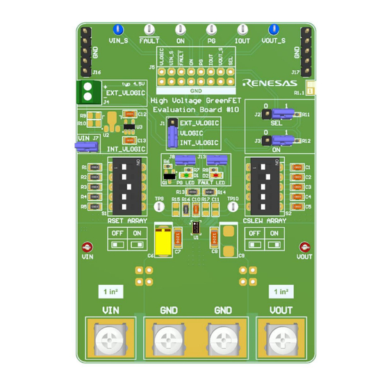
Figure 1. High Voltage GreenFET Evaluation Board #10
Evaluation Board Manual
Features
■
Screw Terminals for VIN, VOUT, GND
■
Internal VLOGIC regulator
■
External VLOGIC terminal
6 hooks + pin header for probe connection
■
■
DIP switches for RSET and CSLEW arrays
■
2-pos pin headers for ON/SEL configuration
̅̅̅̅̅̅̅̅̅̅ indication
LEDs for PG and FAULT
■
Page 1
© 2024 Renesas Electronics
Advertisement
Table of Contents

Subscribe to Our Youtube Channel
Related Manuals for Renesas SLG59H1132V-EVB


Summary of Contents for Renesas SLG59H1132V-EVB
-
Page 1: Figure 1. High Voltage Greenfet Evaluation Board #10
2-pos pin headers for ON/SEL configuration Load Current – up to 6 A ■ ̅̅̅̅̅̅̅̅̅̅ indication LEDs for PG and FAULT ■ Figure 1. High Voltage GreenFET Evaluation Board #10 R16UH0034EU0101 Rev.1.01 Page 1 © 2024 Renesas Electronics Sep 16, 2024... -
Page 2: Table Of Contents
SLG59H1132V Evaluation Board #10 Manual Contents Functional Description ..........................3 Evaluation Board Features ........................... 3 Screw Terminals ............................ 3 Setting Output Current Limit with R ....................4 Setting V Ramping with C ......................4 SLEW Internal/External VLOGIC ........................4 4-Wire (Kelvin) Connection for RDS Measurements ................. -
Page 3: Functional Description
SLG59H1132V Evaluation Board #10 Manual 1. Functional Description This Evaluation Board provides full evaluation capabilities for the SLG59H1132V load switch. It has all the necessary screw terminals to connect input voltage, output load, connectors to measure main parameters and configure input signals. The main components and their basic functions are shown in Figure 6 probe hooks +... -
Page 4: Setting V Out Slew
SLG59H1132V Evaluation Board #10 Manual Screw terminal dimensions are shown in figure below: Figure 4. Screw Terminal Dimensions Setting Output Current Limit with R HV GreenFET Evaluation Board #10 has DIP switch for setting 5 different R values. The R resistors can be chosen by using DIP switch S1: R1 –... -
Page 5: 4-Wire (Kelvin) Connection For Rds
SLG59H1132V Evaluation Board #10 Manual Internal VLOGIC is around 4.4 V LDO regulator and input voltage comes from V power rail. External VLOGIC (max 4.5 V) can be supplied from EXTERNAL VLOGIC Terminal J4. Internal or External logic level voltage can be selected by changing the position of the Jumper on J1 header: EXTERNAL VLOGIC Terminal INTERNAL LDO (4.4V) -
Page 6: Led Indication
SLG59H1132V Evaluation Board #10 Manual VIN_SENSE VOUT_SENSE VIN_SENSE VOUT_SEN SE Hign Voltage VOUT VIN TP VOUT TP GreenFET Figure 11. Block Diagram for 4-Wire Kelvin RDS Measurements VIN_SENSE VOUT_SENSE VIN TP VOUT TP Figure 12. Location of 4-Wire Kelvin Sense TPs LED Indication ̅̅̅̅̅̅̅̅̅̅... -
Page 7: Figure 13. Schematic Connection Of D1 And D2 Leds
SLG59H1132V Evaluation Board #10 Manual VLOGIC VLOGIC 5.1k R0402 LED0603 Red FAULT VOUT VLOGIC 4, 5, 6 9, 10, 11 VOUT R0805 R0805 7, 8 12, 13 VOUT R0402 Green FAULT FAULT LED0603 Green RSET 2N7002 IOUT SOT-23-3, 2.9x1.6mm, P0.95mm SLG59H1132V R0402 Figure 13. -
Page 8: Schematic
SLG59H1132V Evaluation Board #10 Manual 3. Schematic VLOGIC VOUT VLOGIC INTERNAL VLOGIC 47uF 22uF 10uF R0805 C2917 C1206 C1206 C2917 R0402 R0805 30.1k SOT-89-3, 4.5x2.5mm, P1.5mm R0805 VOUT R0805 4, 5, 6 9, 10, 11 RSET ARRAY R0805 VOUT R0805 R0805 7, 8 12, 13... -
Page 9: Bom
SCREW1, SCREW2, SCREW3, 7693 Keystone Electronics SCREW4 TP1, TP8 5117 Keystone Electronics TP2, TP3, TP4, TP7 5002 Keystone Electronics TP5, TP6 5000 Keystone Electronics TP9, TP10 SLG59H1132V Renesas Electronics America Inc AP7383-44WW-7 Diodes Incorporated R16UH0034EU0101 Rev.1.01 Page 9 Sep 16, 2024... -
Page 10: Ordering Information
SLG59H1132V Evaluation Board #10 Manual 5. Ordering Information Part Number Description SLG59H1132V-EVB High Voltage GreenFET Evaluation Board #10 R1.1 6. Revision History Revision Date Description Added n channel MOSFET for driving PG LED. 1.01 Sep 16, 2024 Changed R1, R2, R4 resistor values for current limit settings and C3 value for Slew rate settings. -
Page 11: Corporate Headquarters
Renesas' products are provided only subject to Renesas' Terms and Conditions of Sale or other applicable terms agreed to in writing. No use of any Renesas resources expands or otherwise alters any applicable warranties or warranty disclaimers for these products.
Need help?
Do you have a question about the SLG59H1132V-EVB and is the answer not in the manual?
Questions and answers