Table of Contents
Advertisement
Quick Links
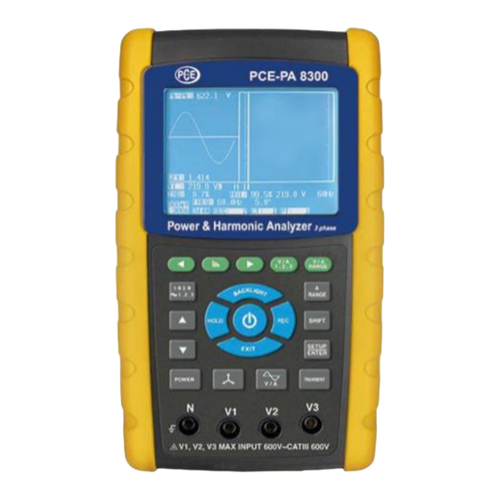
SD card real time data recorder
with harmonic measurement
3 PHASE
Power Meter
PCE-PA 8300
Your
purchase
this 3 PHASE
POWER ANALYZER
marks
a
forward for you into
t h e
f i e l d
p r e c i s i o n
measurement.
A l t h o u g h
POWER ANALYZER
is a complex and
delicate instrument,
its durable structure
will
allow
years
of
use
proper
operating
techniques
developed.
Please
read the following
i n s t r u c t i o n s
carefully and always
keep
this
manual
within easy reach.
of
step
o f
t h i s
many
if
are
Advertisement
Table of Contents

Related Manuals for PCE Instruments PCE-PA 8300


Summary of Contents for PCE Instruments PCE-PA 8300
- Page 1 SD card real time data recorder with harmonic measurement 3 PHASE Power Meter PCE-PA 8300 Your purchase this 3 PHASE POWER ANALYZER marks step forward for you into t h e f i e l d p r e c i s i o n measurement.
- Page 2 Caution Symbol Caution : * Risk of electric shock ! * During the measurement, do not open the cabinet. Caution : * Do not apply the overload voltage, current to the input terminal ! * Remove test leads before open the battery cover ! * Cleaning - Only use the dry cloth to clean the plastic case !
-
Page 3: Table Of Contents
TABLE OF CONTENTS 1. FEATURES..............1 2. SPECIFICATIONS............2 2-1 General Specifications.........2 2-2 Electrical Specifications........5 3. FRONT PANEL DESCRIPTION........10 4. MEASURING PREPARATION ........13 4-1 The original screen..........13 4-2 Entry the measurement Screen......13 4-3 The summary description of keyboard....15 4-4 SETUP KEY description........16 4-5 Setting function description before measuring.. - Page 4 5-13 Backlight key.............66 5-14 A ( Current ) Range key........66 5-15 LOWBAT screen..........67 5-16 Appendix 1............68 6. MAINTENANCE............69 6-1 Cleaning............. 69 6-2 Replacement of batteries ........69 7. RS232 PC SERIAL INTERFACE........70 8. Download the saving data from the SD card to the computer ( EXCEL software ) ......
-
Page 5: Features
1. FEATURES * Analysis for 3 phase multi-power system, 1P/2W, 1P/3W, 3P/3W, 3P/4W. * 3 current probes ( CP-1201 ) are included, if change the current probes, the calibration procedures are not necessary. * Current probe input signal/ranges with selection : Input signal (ACV) : 200 mV/300 mV/500 mV/1 V/2 V/3 V. -
Page 6: Specifications
* ACV input impedance is 10 Mega ohms. * Safety Standard : IEC 1010, CAT III 600V. * Built-in clock and Calendar, real time data record with SD memory card , sampling time set from 2 to 7200 seconds. Just slot in the SD card into the computer, it can down load the all the measured value with the time information ( year, month, data, hour, minute, second ) to the Excel directly, then user can make the further data... - Page 7 Measurement * V (phase-to-phase) * V (phase-to-ground) * A (phase-to-ground) * KW / KVA / KVAR / PF (phase) KW / KVA / KVAR / PF (system) KWH / KVAH / KVARH / PFH (system) * Power factor * Phase angle * Frequency * Harmonics display.
- Page 8 Under Indicator * LCD display show " UR ". * The data save into the SD card will show " 9999 " or " 999 " ( overleap the decimal point ). Data Hold Freeze the display reading. Data Record SD Card Record.
-
Page 9: Electrical Specifications
Weight * Meter : 1010g ( includes batteries ) * Clamp ( includded cable ) : 500g Meter : Dimension 225 X 125 X 64 mm ( 8.86 X 4.92 X 2.52 inch ) Clamp : 210 X 64 X 33mm ( 8.3 X 2.5 X 1.3 inch ) Clamp Jaw : 86 mm (3.4 inch)- outside Accessories... - Page 10 Range Resolution Accuracy 0.001A, < 10 A ± (0.5%+0.1A) 0.01A, 10 A ≧ 200A 0.01A, < 100 A ± (0.5%+0.5A) 0.1A, 100 A ≧ 1200A 0.1A, < 1000 A ± (0.5%+5A) 1000 A ≧ Power factor Range Resolution Accuracy 0.00 to 1.00 0.01 ±...
- Page 11 Active (Real) Power Range Resolution Accuracy 0.000 to 9.999 KW ± (1%+0.008KW) *0.001/0.01/0.1 KW 10.00 to 99.99 KW ± (1%+0.08KW) *0.01/0.1 KW 100.0 to 999.9 KW ± (1%+0.8KW) 0.1 KW 1.000 to 9.999 MW ± (1%+0.008MW) 0.001 MW * : The resolution is changed according the different ACA range. Apparent Power Range Resolution...
- Page 12 VA Hour ( Apparent Power Hour ) : SH Range Resolution Accuracy 0.000 to 9.999 KVAH 0.001 KVAH ± (2%+0.008 KVAH) 10.00 to 99.99 KVAH 0.01 KVAH ± (2%+0.08 KVAH) 100.0 to 999.9 KVAH 0.1 KVAH ± (2%+0.8 KVAH) 1.000 to 9.999 MVAH 0.001 MVAH ±...
- Page 13 Harmonics of AC current in Percentage * Fundamental frequency 50 Hz, 60 Hz Range Resolution Accuracy 1 to 20th ± ( 2 % + 10 d ) 21 to 30th 0.1 % ± ( 4 % + 20 d ) 31 to 50th reference Peak value of ACV or ACA...
-
Page 14: Front Panel Description
3. FRONT PANEL DESCRIPTION Fig. 1... - Page 15 3-1 Display 3-2 1Φ 3Φ ( Phase/wire ) key button key button ▲ key button ▼ 3-5 Hold key button 3-6 Backlight key button 3-7 Power key button 3-8 Exit key button 3-9 REC key button 3-10 A ( current ) range key button 3-11 Shift key button 3-12 Setup key button 3-13 Voltage input terminals...
- Page 16 3-24 Harmonic Analysis Left Key 3-25 Harmonic Key 3-26 Harmonic Analysis Right Key 3-27 Harmonic Analysis V1,V2,V3, A1,A2,A3 Select Key 3-28 Harmonic Function Voltage or Current Input Range 3-29 Power Measurement Key 3-30 Phase Diagram Key 3-31 Waveform of Voltage and Current Key 3-32 Transient Key...
-
Page 17: Measuring Preparation
4. MEASURING PREPARATION 4-1 The original screen 4-2 Entry the measurement Screen 1)The bottom right display of screen 1 will show as " SD Check " along with blinking while inserting SD CARD then disappears after several seconds that indicates the data from SD CARD has been read completed. - Page 18 screen 1 ( 4-2 ) V12: 0.0 V 0.0 V 0.00 A V23: 0.0 V 0.0 V 0.00 A V31: 0.0 V 0.0 V 0.00 A -0.000 KW 0.000KVA -0.000 KVAR -0.000 KW 0.000KVA -0.000 KVAR -0.000 KW 0.000KVA -0.000 KVAR PΣ...
-
Page 19: The Summary Description Of Keyboard
4-3 The summary description of keyboard 1) POWER KEY ( 3-7, Fig. 1 ) : Press the key to turn the instrument ON/OFF. 2) 1Φ 3Φ ( phase/wire ) KEY ( 3-2, Fig. 1 ) : Press the key to select (1P/2W、1P/3W、3P/3W、3P/4W) measurement function mode. -
Page 20: Setup Key Description
4-4 SETUP KEY description: 4-4-1 SHIFT KEY * SHIFT 1 : When the symbols " SETUP " and " SHIFT 1 " are appeared on up right display of screen 1 in the meantime, and then use the to select the ▲... -
Page 21: Setting Function Description Before Measuring
4-4-2 The Setting Function menu * Folder Name : Set the expect folder name for SD CARD, the range is between WTA01 and WTA10. * File Name: Set the file name for SD CARD, It allows setting 50 filenames in this function. * REC Date: Show the recorded time of existing files ( Year/Month/Date, Hour/Min./Sec. - Page 22 4-5-1 Folder Name: Set the folder name for SD screen 1 ( 4-5-1 ) Folder Name: WTA01 SETUP File Name: 3P401001.XLS REC Date: 2008-11-28 00:03:17 Sampling Time: Trans Ref : 220.0 V Delet File: SDVP : SD Format: Decimal: Basic Use Size: 388 KB Clamp Type:...
- Page 23 A : Folder Name range: WTA01 to WTA10. B : Press to select the expect folder number, the ▲ ▼ number consists of " 01 to 10 " (as screen 1). C : Press continuously at least two seconds can ▲...
- Page 24 screen 2 ( 4-5-2 ) Folder Name: WTA01 SETUP File Name: 3P401001.XLS REC Date: 2008-11-28 00:03:17 Sampling Time: Trans Ref : 220.0 V Delet File: SDVP : SD Format: Decimal: Basic Use Size: 388 KB Clamp Type: CP1201 Free Size: 1946 MB Range: 200A...
- Page 25 E : The up right display will show " SHIFT2 " symbol while pressing SHIFT KEY again in screen 4, at this time press ▲ or ▼ to select 1P/2W(1P2)、1P/3W(1P3)、 3P/3W(3P3) and 3P/4W(3P4) as screen 4. F: One by one to press SHIFT KEY to select different functions circularly.
- Page 26 4-5-3 Sampling time: Set the data logger sampling time for SD A : When press SHIFT KEY once, the symbol " SHIFT1 " will disappear on up right display, at this time press to adjust expect sampling time as screen 2, ▲...
- Page 27 4-5-4 Delete File: Delete the files for SD A : The indicator " Y or N " will appear on right side display of the option while pressing SHIFT KEY continuously at least two seconds, and now press ▲ the display will show " Y " in highlight as screen 2, press SETUP KEY again to confirm, the selected file (ex: 3P401001.XLS) will be erased then return to screen 1, or else press SETUP KEY in "...
- Page 28 screen 2 ( 4-5-4 ) Folder Name: WTA01 SETUP File Name: 3P401001.XLS SHIFT 1 REC Date: 2008-11-28 00:03:17 Sampling Time: Trans Ref : 220.0 V Delete File: Y OR N SDVP : SD Format: Decimal: Basic Use Size: 388 KB Clamp Type: CP1201 Free Size:...
- Page 29 screen 1 ( 4-5-5 ) Folder Name: WTA01 SETUP File Name: 3P401001.XLS SHIFT 1 REC Date: 2008-11-28 00:03:17 Sampling Time: Trans Ref : 220.0 V Delete File: SDVP : SD Format: Decimal: Basic Use Size: 388 KB Clamp Type: CP1201 Free Size: 1946 MB Range:...
- Page 30 4-5-6 PT: Set the Potential Transformer A : When press SHIFT KEY once, the symbol " SHIFT1 " will disappear as screen 2 at this time press ▲ ▼ adjust to expect PT values, the adjusting numbers are from 1 to 1000. Remark : When press >...
- Page 31 screen 2 ( 4-5-6 ) Folder Name: WTA01 SETUP File Name: 3P401001.XLS REC Date: 2008-11-28 00:03:17 Sampling Time: Trans Ref : 220.0 V Delete File: SDVP : SD Format: Decimal: Basic Use Size: 388 KB Clamp Type: CP1201 Free Size: 1946 MB Range: 200A...
- Page 32 screen 1 ( 4-5-7 ) Folder Name: WTA01 SETUP File Name: 3P401001.XLS SHIFT 1 REC Date: 2008-11-28 00:03:17 Sampling Time: Trans Ref : 220.0 V Delete File: SDVP : SD Format: Decimal: Basic Use Size: 388 KB Clamp Type: CP1201 Free Size: 1946 MB Range:...
- Page 33 4-5-8 Beep: Control the buzzer to ON/OFF A : When press SHIFT KEY once the symbol " SHIFT1 " will disappear as screen 2, at this time press ▲ ▼ control the buzzer to ON/OFF. B : Press SHIFT KEY once again will return to screen 1 then press to enter next setting function ( BEEP Trans Ref...
- Page 34 screen 2 ( 4-5-8 ) Folder Name: WTA01 SETUP File Name: 3P401001.XLS REC Date: 2008-11-28 00:03:17 Sampling Time: Trans Ref : 220.0 V Delete File: SDVP : SD Format: Decimal: Basic Use Size: 388 KB Clamp Type: CP1201 Free Size: 1946 MB Range: 200A...
- Page 35 screen 1 ( 4-5-9 ) Folder Name: WTA01 SETUP File Name: 3P401001.XLS SHIFT 1 REC Date: NO File Sampling Time: Trans Ref : 220.0 V Delete File: SDVP : SD Format: Decimal: Basic Use Size: 23 MB Clamp Type: CP1201 Free Size: 1904 MB Range:...
- Page 36 4-5-10 SDVP: Set up upper and low limits % of transient voltage detection A : When press SHIFT KEY once will disappear as screen 2, at this time press to adjsut the voltage % value ▲ ▼ to 1% to 100%. B : Press SHIFT KEY once again will return to screen 1 then press to enter next setting function ( SDVP...
- Page 37 screen 2 ( 4-5-10 ) Folder Name: WTA01 SETUP File Name: 3P401026.XLS REC Date: NO File Sampling Time: Trans Ref : 220.0 V Delete File: SDVP : SD Format: Decimal: Basic Use Size: 23 MB Clamp Type: CP1201 Free Size: 1904 MB Range: 200A...
- Page 38 * Basic type : The numerical data structure of SD card is default used the " . " as the decimal, for example "20.6" "1000.53" . * Euro type : The numerical data structure of SD card is default used the " , " as the decimal, for example "20,6"...
- Page 39 screen 2 ( 4-5-11 ) Folder Name: WTA01 SETUP File Name: 3P401001.XLS REC Date: 2008-11-28 00:03:17 Sampling Time: Trans Ref : 220.0 V Delete File: SDVP : SD Format: Decimal: Basic Use Size: 388 KB Clamp Type: CP1201 Free Size: 1946 MB Range: 200A...
- Page 40 screen 1 ( 4-5-12 ) Folder Name: WTA01 SETUP File Name: 3P401001.XLS SHIFT 1 REC Date: 2008-11-28 00:03:17 Sampling Time: Trans Ref : 220.0 V Delete File: SDVP : SD Format: Decimal: Basic Use Size: 388 KB Clamp Type: CP1201 Free Size: 1946 MB Range:...
- Page 41 4-5-13 A range Setting ( Current range Setting ) A : When press SHIFT KEY once the symbol " SHIFT1 " will be disappeared and show as screen 2, at this time press to select A range to 20A to 2000A or ▲...
- Page 42 screen 2 ( 4-5-13 ) Folder Name: WTA01 SETUP File Name: 3P401001.XLS REC Date: 2008-11-28 00:03:17 Sampling Time: Trans Ref : 220.0 V Delete File: SDVP : SD Format: Decimal: Basic Use Size: 388 KB Clamp Type: CP1201 Free Size: 1946 MB Range: 200A...
- Page 43 screen 1 ( 4-5-14 ) Folder Name: WTA01 SETUP File Name: 3P401001.XLS SHIFT 1 REC Date: 2008-11-28 00:03:17 Sampling Time: Trans Ref : 220.0 V Delete File: SDVP : SD Format: Decimal: Basic Use Size: 388 KB Clamp Type: CP1201 Free Size: 1946 MB Range:...
- Page 44 4-5-15 RS232 Out Sel setting A : When press SHIFT KEY continuously at least two seconds as screen 2 and now press to select ▲ ▼ the item that intend to output, maximum up to nine items, when the cursor stops on the selected item and then press SETUP KEY again, the selected item will be displayed in highlight.
- Page 45 screen 2 ( 4-5-15 ) RS232 OUTPUT SELECT 12. P3 23. PF2 13. PΣ 24. PF3 25. PFΣ 15. S2 26. PFH 16. S3 Φ 1 17. SΣ 28. Φ 2 29. Φ 3 19. Q2 20. Q3 31. SH 21.
- Page 46 screen 4 ( 4-5-15 ) RS232 OUTPUT SELECT 78. H45 Φ V12 68. H35 79. H46 Φ V23 69. H36 Φ V31 70. H37 81. H48 Φ V1 71. H38 82. H49 Φ V2 72. H39 83. H50 Φ V3 73.
- Page 47 screen 6 ( 4-5-15 ) RS232 OUTPUT SELECT 12. P3 23. PF2 13. PΣ 24. PF3 25. PFΣ 15. S2 26. PFH 16. S3 Φ 1 17. SΣ 28. Φ 2 29. Φ 3 19. Q2 20. Q3 31. SH 21.
- Page 48 D : In this setting function ( Year Minute ), press → ▲ in addition to adjust the numbers, and the setting ▼ value will also be saved during the adjusting. E : In the function of setting " second ", press ▲...
- Page 49 Folder Name: WTA01 SETUP File Name: 3P401001.XLS REC Date: 2008-11-28 00:03:17 Sampling Time: Trans Ref : 220.0 V screen 2 Delete File: SDVP : ( 4-5-16 ) SD Format: Decimal: Basic Use Size: 388 KB Clamp Type: CP1201 Free Size: 1946 MB Range: 200A...
-
Page 50: Measuring Procedures
5. MEASURING PROCEDURES 5-1 1Φ 2W ( one phase by two wires ) measurement A : Diagram SCREEN 1 ( 5-1 ) B : Operation Instructions: B-1 : Power on the instrument by pressing POWER KEY, and then press 1Φ 3Φ KEY to select the 1Φ 2W system, the selected name of system will be appeared on bottom left display of screen 2. -
Page 51: 3W (One Phase By Three Wires) Measurement
screen 2 ( 5-1 ) V 1 : A 1 : 0.00 P 1 : - 0.000KW P F 1 : - 0.00 S 1 : 0.000KVA P F H : 0.00 Q 1 : - 0.000KVAR Φ 1 : - 0.0°... - Page 52 B : Operation Instructions: B-1 : Power on the instrument by pressing POWER KEY, and then press 1Φ 3Φ KEY to select the 1Φ 3W system, the selected name of system will be appeared on bottom left display of screen 2. B-2 : Connect the line voltage L1, L2 and Vn (Neutral) to V1, V2 and N terminals of the instrument.
-
Page 53: 3W ( Three Phase By Three Wires ) Measurement
5-3 3Φ 3W (three phases by three wires) measurement A : Diagram screen 1 ( 5-3 ) B : Operation Instructions: B-1 : Power on the instrument by pressing POWER KEY, and then press 1Φ 3Φ KEY to select the 3Φ 3W system, the selected name of system will be appeared on bottom left display of screen 2. -
Page 54: 4W ( Three Phase By Four Wires ) Measurement
screen 2 ( 5-3 ) V 1 2 : A 1 : 0.00 V 2 3 : A 2 : 0.00 V 3 1 : A 3 : 0.00 P Σ : - 0.000 KW S Σ : 0.000 KVA Q Σ... - Page 55 B: Operation Instructions: B-1 : Power on the instrument by pressing POWER KEY, and then press 1Φ 3Φ KEY to select the 3Φ 4W system, the selected name of system will be appeared on bottom left display of screen 2. B-2 : Connect the line voltage L1, L2, L3 and Vn to V1, V2, V3 and N terminals of the instrument.
-
Page 56: The Ct And Pt Measurement
5-5 The CT and PT measurement A : Diagram screen 1 ( 5-5 ) B : Operation Instructions B-1 : Power on the instrument by pressing POWER KEY, and then press 1Φ 3Φ KEY to select the 3Φ 4W system, the selected name of system will be appeared on bottom left display of screen 2. -
Page 57: Zero Adjustment For Watt Hour
screen 2 ( 5-5 ) V12: 0.0 V 0.0 V 0.00 V23: 0.0 V 0.0 V 0.00 V31: 0.0 V 0.0 V 0.00 - 0.000 KW 0.000 KVA - 0.000 KVAR - 0.000 KW 0.000 KVA - 0.000 KVAR - 0.000 KW 0.000 KVA - 0.000 KVAR PΣ... -
Page 58: Harmonic Function Measurement
5-7 Harmonic Function Measurement 1) Press " Harmonic Key " ( 3-25, Fig. 1 ) will enter the Screen 1. 2) Press " V/A 1. 2. 3 Key " ( 3-27, Fig. 1 ) will enter the Screen 2. 3) If the wave show the distortion, Press " V/A range Key " ( 3-28, Fig. - Page 59 Screen 2 ( 5-7 ) Pk-Pk : 216.0 A CFA : 1.414 A1 : 70.47 THD: 5.5% HD1: 100.0% 70.47A 60Hz 1.8° CP1201 FREQ: 59.9Hz 200A 3Φ 4W SEC: 2 CT: 1 PT: 2 Screen 3 ( 5-7 ) Pk-Pk : 623.1 V CFV : 1.414...
-
Page 60: Graphic Phasor Diagram
Screen 4 ( 5-7 ) Pk-Pk : 201.6 A CFA : 1.414 A1 : 73.97 THD: 5.0% HD1: 99.5% 73.63A 60Hz 3.0° CP1201 FREQ: 59.9Hz 200A 3Φ 4W SEC: 2 CT: 1 PT: 2 5-8 Graphic Phasor Diagram 1) Press " Phase Diagram Key " ( 3-30, Fig. 1 ) will display the phasor diagram as the Screen 1. - Page 61 f. do2 ( do, d2 ) : do - The first number is Zero Sequence Unbalance Ratio in % ( d0 ) of voltage or current. d2 - The second number is the Negative Sequence Unbalance Ratio in % ( d2 ) of voltage or current. g.
-
Page 62: Voltage/Current Waveform
Screen 2 ( 5-8 ) 5-9 Voltage/Current Waveform 1) Press " Waveform Key " ( 3-31, Fig. 1 ) will enter to Voltage Waveform screen as Screen 1, then Press " 1Φ /3Φ Key " ( 3-2, Fig. 1 ) once in sequence will switch the Voltage waveform from V1 to V2, V3. - Page 63 Screen 1 ( 5-9 ) Screen 2 ( 5-9 )
-
Page 64: Transient Capture ( Dips, Swells, Outage )
Screen 3 ( 5-9 ) 5-10 Transient Capture ( Dips, Swells, Outage ) 1) If intend to make the Transient Capture measurement it should set the transient voltage level ( high level, low level ) at first , the setting procedures, please refere to chapter 4-5-9 and chapter 4-5-10. - Page 65 d. Line item : * V is the code show the all phase V1, V2, V3 ever happen the transient event. * V1, V2, V3 is the code that show each phase V1, V2, V3 ever happen the transient event. * Refer to Screen 2.
- Page 66 Screen 2 ( 5-10 ) Screen 3 ( 5-10 )
-
Page 67: Data Logger Function
5-11 Data Logger Function A : Press REC KEY once to start the data record function. A-1 : If the bottom right shows as " Change Card ", it indicates the memory space is already full either or the SD CARD exist some wrong. A-2 : If the SD CARD is normal, the data logger function will start to be executed. - Page 68 screen 1 ( 5-11 B ) V12: 0.0 V 0.0 V 0.00 V23: 0.0 V 0.0 V 0.00 V31: 0.0 V 0.0 V 0.00 - 0.000 KW 0.000 KVA - 0.000 KVAR - 0.000 KW 0.000 KVA - 0.000 KVAR - 0.000 KW 0.000 KVA - 0.000 KVAR...
-
Page 69: Data Hold Function
5-12 Data HOLD Function A: During the measurement, press HOLD KEY once, the bottom right display will show “ HOLD symbol as screen 1. B: Press the HOLD KEY twice will disable the Data HOLD function and the “ HOLD” symbol will disappear in the meantime screen 1 ( 5-12 ) V12:... -
Page 70: Backlight Key
5-13 BACKLIGHT KEY Control the backlight function of LCD to ON/OFF 5-14 A Range ( Current Range ) KEY function a) The A Range ( Current Range ) function key is used to change the current range quickly. b)Press A RANGE KEY once will entry to screen as following "... -
Page 71: Lowbat Screen
5-15 The LOWBAT screen: as show on lower right display of the following screen. V12: 0.0 V 0.0 V 0.00 V23: 0.0 V 0.0 V 0.00 V31: 0.0 V 0.0 V 0.00 - 0.000 KW 0.000 KVA - 0.000 KVAR - 0.000 KW 0.000 KVA - 0.000 KVAR... - Page 72 5-16 Appendix 1 * V12, V23, V31 : Line Voltage * V1, V2, V3 : Phase Voltage * A1, A2, A3 : Line Current * P1, P2, P3 : True Power of each phase. (W) * S1, S2, S3 : Apparent Power of each phase. (VA) * Q1, Q2, Q3 : Reactive Power of each phase (VAR) * PΣ...
-
Page 73: Maintenance
6. MAINTENANCE Remove test leads before Caution : opening the battery cover or housing case ! 6-1 Cleaning Cleaning - Only use Caution : the dry cloth to clean the plastic case ! 6-2 Replacement of batteries 1) When Display show the " LOWBAT " indicator ( ref. 5-15 page 67 ), it should change the batteries. -
Page 74: Rs232 Pc Serial Interface
7. RS232 PC SERIAL OUTPUT The instrument is provided an 3.5 mm dia. phone socket ( 3-16, Fig. 1 ) for RS232 computer interface socket. The connector output is a 16 digits data stream which can be utilized to the user's specific application. A RS232 lead with the following connection will be required to link the instrument with the PC serial input. - Page 75 Each digit indicate the following status : Start Word D12 & D11 Annunciator for Display 03=% B9 = MACA D0 = MW/Hr 31=HZ C0 = MW D1 = GW/Hr 32=DEGREE C1 = GW D2 = TW/Hr 48=K WATT C2 = TW D3 = KVA/Hr 50=ACV C3 = MVA...
-
Page 76: Download The Saving Data From The Sd Card To The Computer ( Excel Software )
8. Download the saving data from the SD card to the computer ( EXCEL software ) 1) After execute the Data Logger function, take away the SD card out from the " SD card socket " ( 3-15, Fig. 1 ). 2) Plug in the SD card into the Computer's SD card slot ( if your computer build in this installation ) or insert the SD card into the "... - Page 77 EXCEL data screen 2 ( for example ) EXCEL data screen 3 ( for example ) EXCEL data screen 4 ( for example )
- Page 78 EXCEL data screen 5 ( for example ) EXCEL data screen 6 ( for example ) EXCEL graphic screen 1 ( for example )
- Page 79 EXCEL graphic screen 2 ( for example ) EXCEL graphic screen 3 ( for example )
-
Page 80: Patent
EXCEL graphic screen 4 ( for example ) EXCEL graphic screen 5 ( for example ) 9. PATENT The meter ( SD card structure ) already get patent or patent pending in following countries :... -
Page 81: The Address Of After Service Center
Germany Nr. 20 2008 016 337.4 JAPAN 3151214 TAIWAN M 358970 M 359043 CHINA ZL 2008 2 0189918.5 ZL 2008 2 0189917.0 Patent pending 10. THE ADDRESS OF AFTER SERVICE CENTER 1106-DW6095 1012-DW6095...
Need help?
Do you have a question about the PCE-PA 8300 and is the answer not in the manual?
Questions and answers