Table of Contents
Advertisement
Quick Links
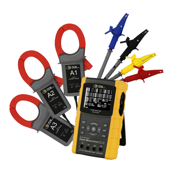
SD card real time data logger
3 PHASE
POWER ANALYZER
Model : PCE-PA 8000
OPERATION MANUAL
Your purchase of
this 3 PHASE
POWER ANALYZER
marks
a
forward for you into
t h e
f i e l d
p r e c i s i o n
measurement.
A l t h o u g h
POWER ANALYZER
is a complex and
delicate instrument,
its durable structure
will
allow
many
years
of
use
proper
operating
techniques
developed.
Please
read the following
i n s t r u c t i o n s
carefully and always
keep this manual
within easy reach.
step
o f
t h i s
if
are
Advertisement
Table of Contents

Related Manuals for PCE Instruments PCE-PA 8000


Summary of Contents for PCE Instruments PCE-PA 8000
- Page 1 SD card real time data logger 3 PHASE POWER ANALYZER Model : PCE-PA 8000 Your purchase of this 3 PHASE POWER ANALYZER marks step forward for you into t h e f i e l d p r e c i s i o n measurement.
- Page 2 Caution Symbol Caution : * Risk of electric shock ! * During the measurement, do not open the cabinet. Caution : * Do not apply the overload voltage, current to the input terminal ! * Remove test leads before open the battery cover ! * Cleaning - Only use the dry cloth to clean the plastic case !
-
Page 3: Table Of Contents
TABLE OF CONTENTS 1. FEATURES..................2. SPECIFICATIONS................2-1 General Specifications..............2-2 Electrical Specifications..........3. FRONT PANEL DESCRIPTION............. 4. MEASURING PREPARATION ............4-1 The original screen..........10 4-2 Entry the measurement Screen....... 10 4-3 The summary description of keyboard....12 4-4 SETUP KEY description.........13 4-5 Setting function description before measuring... -
Page 4: Features
1. FEATURES * Analysis for 3 phase multi-power system, 1P/2W, 1P/3W, 3P/3W, 3P/4W * Voltage & Current are the True RMS value. * True Power ( KW、MW、GW ) measurement. * Apparent Power ( KVA、MVA、GVA ) measurement. * Reactive Power ( KVAR MVAR、GVAR) measurement. * Watt-Hour ( WH、SH、QH、PFH ). -
Page 5: Specifications
2. SPECIFICATIONS 2-1 General Specifications: Circuit Custom one-chip of microprocessor LSI circuit Display * LCD Size : 81.4 X 61 mm ( 3.2 X 2.4 inch ) * Dot Matrix LCD (320 X 240 pixels ) with back light. Measurement * ACV * ACA * AC WATT ( True Power ) - Page 6 Over Indicator Show " OL ". Under Indicator Show " UR ". Data Hold Freeze the display reading. Data Record SD Card Record. Sampling Time Approx. 1 second. Power ON/OFF Manual OFF by push button. Real time * Real time data logger, saved the data data logger into SD memory card and down load the all the measured value with the...
-
Page 7: Electrical Specifications
Weight * Meter : 948g ( includes batteries ) * Clamp ( includded cable ) : 467g Meter : Dimension 225 X 125 X 64 mm ( 8.86 X 4.92 X 2.52 inch ) Clamp : 210 X 64 X 33mm ( 8.3 X 2.5 X 1.3 inch ) Clamp Jaw : 86 mm (3.4 inch)- outside Accessories... - Page 8 Range Resolution Accuracy 0.001A, < 10 A ± (0.5%+0.1A) 0.01A, ≧ 10 A 200A 0.01A, ± (0.5%+0.5A) < 100 A 0.1A, ≧ 100 A 1200A 0.1A, < 1000 A ± (0.5%+5A) ≧ 1000 A Power factor Range Resolution Accuracy 0.00 to 1.00 0.01 ±...
- Page 9 Active (Real) Power Accuracy Range Resolution 0.000 to 9.999 KW ± (1%+0.008KW) *0.001/0.01/0.1 KW 10.00 to 99.99 KW ± (1%+0.08KW) *0.01/0.1 KW 100.0 to 999.9 KW ± (1%+0.8KW) 0.1 KW 1.000 to 9.999 MW ± (1%+0.008MW) 0.001 MW * : The resolution is changed according the different ACA range. Apparent Power Range Resolution...
- Page 10 Watt Hour ( Active Power Hour) : WH Range Resolution Accuracy 0.000 to 9.999 KWH 0.001 KWH ± (2%+0.008 KWH) 10.00 to 99.99 KWH 0.01 KWH ± (2%+0.08 KWH) 100.0 to 999.9 KWH 0.1 KWH ± (2%+0.8 KWH) 1.000 to 9.999 MWH 0.001 MWH ±...
-
Page 11: Front Panel Description
3. FRONT PANEL DESCRIPTION... - Page 12 3-1 Display 3-2 1Φ 3Φ ( Phase/wire ) key button ▲ key button ▼ key button 3-5 Hold key button 3-6 Backlight key button 3-7 Power key button 3-8 Exit key button 3-9 REC key button 3-10 A ( current ) range key button 3-11 Shift key button 3-12 Setup key button 3-13 Voltage input terminals...
-
Page 13: Measuring Preparation
4. MEASURING PREPARATION 4-1 The original screen 4-2 Entry the measurement Screen 1)The bottom right display of screen 1 will show as " SD Check " along with blinking while inserting SD CARD then disappears after several seconds that indicates the data from SD CARD has been read completed. - Page 14 screen 1 ( 4-2 ) V12: 0.0 V 0.0 V 0.00 A V23: 0.0 V 0.0 V 0.00 A V31: 0.0 V 0.0 V 0.00 A -0.000 KW 0.000KVA -0.000 KVAR -0.000 KW 0.000KVA -0.000 KVAR -0.000 KW 0.000KVA -0.000 KVAR PΣ...
-
Page 15: The Summary Description Of Keyboard
4-3 The summary description of keyboard 1)POWER KEY ( 3-7, Fig. 1 ) : Press the key to turn the instrument ON/OFF. 2)1Φ 3Φ ( phase/wire ) KEY ( 3-2, Fig. 1 ) : Press the key to select (1P/2W、1P/3W、3P/3W、3P/4W) measurement function mode. -
Page 16: Setup Key Description
4-4 SETUP KEY description: 4-4-1 SHIFT KEY * SHIFT 1 : When the symbols " SETUP " and " SHIFT 1 " are appeared on up right display of screen 1 in the ▲ ▼ meantime, and then use the to select the expect item. -
Page 17: Setting Function Description Before Measuring
4-4-2 The Setting Function menu * Folder Name : Set the expect folder name for SD CARD, the range is between WTA01 and WTA10. * File Name: Set the file name for SD CARD, It allows setting 50 filenames in this function. * REC Date: Show the recorded time of existing files ( Year/Month/Date, Hour/Min./Sec. - Page 18 4-5-1 Folder Name: Set the folder name for SD screen 1 ( 4-5-1 ) Folder Name: WTA01 SETUP File Name: 3P401001.XLS REC Date: 2008-11-28 00:03:17 Sampling Time: Delet File: SD Format: Use Size: 388 KB Decimal: Basic Free Size: 1946 MB Clamp Type: 1200A Total Size: 1946 MB...
- Page 19 A : Folder Name range: WTA01 to WTA10. ▲ ▼ B : Press to select the expect folder number, the number consists of " 01 to 10 " (as screen 1). ▲ ▼ C : Press continuously at least two seconds can skip the numbers faster.
- Page 20 screen 2 ( 4-5-2 ) Folder Name: WTA01 SETUP File Name: 3P401001.XLS REC Date: 2008-11-28 00:03:17 Sampling Time: Delet File: SD Format: Use Size: 388 KB Decimal: Basic Free Size: 1946 MB Clamp Type: 1200A Total Size: 1946 MB RS232 Out Sel: 1 : 1 1 : 1 Φ1...
- Page 21 E : The up right display will show " SHIFT2 " symbol while pressing SHIFT KEY again in screen 4, at this time press ▲ or ▼ to select 1P/2W(1P2)、1P/3W(1P3)、 3P/3W(3P3) and 3P/4W(3P4) as screen 4. F: One by one to press SHIFT KEY to select different functions circularly.
- Page 22 4-5-3 Sampling time: Set the data logger sampling time for SD A : When press SHIFT KEY once, the symbol " SHIFT1 " will disappear on up right display, at this time press ▲ ▼ to adjust expect sampling time as screen 2, adjusting numbers are from 2 to 7200 seconds.
- Page 23 4-5-4 Delete File: Delete the files for SD A : The indicator " Y or N " will appear on right side display of the option while pressing SHIFT KEY continuously at least two seconds, and now press ▲ the display will show " Y " in highlight as screen 2, press SETUP KEY again to confirm, the selected file (ex: 3P401001.XLS) will be erased then return to screen 1, or else press SETUP KEY in "...
- Page 24 screen 2 ( 4-5-4 ) Folder Name: WTA01 SETUP File Name: 3P401001.XLS SHIFT 1 REC Date: 2008-11-28 00:03:17 Sampling Time: Delete File: Y OR N SD Format: Use Size: 388 KB Decimal: Basic Free Size: 1946 MB Clamp Type: 1200A Total Size: 1946 MB RS232 Out Sel:...
- Page 25 screen 1 ( 4-5-5 ) Folder Name: WTA01 SETUP File Name: 3P401001.XLS SHIFT 1 REC Date: 2008-11-28 00:03:17 Sampling Time: Delete File: SD Format: Use Size: 388 KB Decimal: Basic Free Size: 1946 MB Clamp Type: 1200A Total Size: 1946 MB RS232 Out Sel: 1 : 1 1 : 1...
- Page 26 4-5-6 PT: Set the Potential Transformer A : When press SHIFT KEY once, the symbol " SHIFT1 " ▲ ▼ will disappear as screen 2 at this time press adjust to expect PT values, the adjusting numbers are from 1 to 1000. ▲...
- Page 27 screen 2 ( 4-5-6 ) Folder Name: WTA01 SETUP File Name: 3P401001.XLS REC Date: 2008-11-28 00:03:17 Sampling Time: Delete File: SD Format: Use Size: 388 KB Decimal: Basic Free Size: 1946 MB Clamp Type: 1200A Total Size: 1946 MB RS232 Out Sel: 1 : 1 1 : 1 Φ1...
- Page 28 screen 1 ( 4-5-7 ) Folder Name: WTA01 SETUP File Name: 3P401001.XLS SHIFT 1 REC Date: 2008-11-28 00:03:17 Sampling Time: Delete File: SD Format: Use Size: 388 KB Decimal: Basic Free Size: 1946 MB Clamp Type: 1200A Total Size: 1946 MB RS232 Out Sel: 1 : 1 1 : 1...
- Page 29 4-5-8 Beep: Control the buzzer to ON/OFF A : When press SHIFT KEY once the symbol " SHIFT1 " will ▲ ▼ disappear as screen 2, at this time press control the buzzer to ON/OFF. B : Press SHIFT KEY once again will return to screen 1 then ▼...
- Page 30 screen 2 ( 4-5-8 ) Folder Name: WTA01 SETUP File Name: 3P401001.XLS REC Date: 2008-11-28 00:03:17 Sampling Time: Delete File: SD Format: Use Size: 388 KB Decimal: Basic Free Size: 1946 MB Clamp Type: 1200A Total Size: 1946 MB RS232 Out Sel: 1 : 1 1 : 1 Φ1...
- Page 31 * Basic type : The numerical data structure of SD card is default used the " . " as the decimal, for example "20.6" "1000.53" . * Euro type : The numerical data structure of SD card is default used the " , " as the decimal, for example "20,6"...
- Page 32 screen 2 ( 4-5-9 ) Folder Name: WTA01 SETUP File Name: 3P401001.XLS REC Date: 2008-11-28 00:03:17 Sampling Time: Delete File: SD Format: Use Size: 388 KB Decimal : Basic Free Size: 1946 MB Clamp Type: 1200A Total Size: 1946 MB RS232 Out Sel: 1 : 1 1 : 1...
- Page 33 screen 1 ( 4-5-10 ) Folder Name: WTA01 SETUP File Name: 3P401001.XLS SHIFT 1 REC Date: 2008-11-28 00:03:17 Sampling Time: Delete File: SD Format: Use Size: 388 KB Decimal: Basic Free Size: 1946 MB Clamp Type: 1200A Total Size: 1946 MB RS232 Out Sel: 1 : 1 1 : 1...
- Page 34 4-5-11 RS232 Out Sel setting A : When press SHIFT KEY continuously at least two ▲ ▼ seconds as screen 2 and now press to select the item that intend to output, maximum up to nine items, when the cursor stops on the selected item and then press SHIFT KEY again, the selected item will be displayed in highlight.
- Page 35 screen 2 ( 4-5-11 ) RS232 OUTPUT SELECT 12. P3 23. PF2 13. PΣ 24. PF3 25. PFΣ 15. S2 26. PFH 16. S3 Φ 1 17. SΣ 28. Φ 1 2 29. Φ 1 3 19. Q2 20. Q3 31.
- Page 36 4-5-12 Year/Month/Date/Hour/Minute/Second setting A : When press SHIFT KEY once the symbol " SHIFT1" ▲ ▼ will disappear as screen 2, at this time press ▲ ▼ to adjust expect numbers, and press continuously at least two seconds can skip the numbers faster.
- Page 37 Folder Name: WTA01 SETUP File Name: 3P401001.XLS REC Date: 2008-11-28 00:03:17 Sampling Time: screen 2 Delete File: ( 4-5-12 ) SD Format: Use Size: 388 KB Decimal: Basic Free Size: 1946 MB Clamp Type: 1200A Total Size: 1946 MB RS232 Out Sel: 1 : 1 1 : 1 Beep:...
-
Page 38: Measuring Procedures
5. MEASURING PROCEDURES 5-1 1Φ 2W ( one phase by two wires ) measurement A : Diagram SCREEN 1 ( 5-1 ) B : Operation Instructions: B-1 : Power on the instrument by pressing POWER KEY, and then press 1Φ 3Φ KEY to select the 1Φ 2W system, the selected name of system will be appeared on bottom left display of screen 2. -
Page 39: 3W (One Phase By Three Wires) Measurement
screen 2 ( 5-1 ) V 1 : A 1 : 0.00 P 1 : - 0.000KW P F 1 : - 0.00 S 1 : 0.000KVA P F H : 0.00 Q 1 : - 0.000KVAR Φ 1 : : - 0.0°... - Page 40 B : Operation Instructions: B-1 : Power on the instrument by pressing POWER KEY, and then press 1Φ 3Φ KEY to select the 1Φ 3W system, the selected name of system will be appeared on bottom left display of screen 2. B-2 : Connect the line voltage L1, L2 and Vn (Neutral) to V1, V2 and N terminals of the instrument.
-
Page 41: 3W ( Three Phase By Three Wires )
5-3 3Φ 3W (three phases by three wires) measurement A : Diagram screen 1 ( 5-3 ) B : Operation Instructions: B-1 : Power on the instrument by pressing POWER KEY, and then press 1Φ 3Φ KEY to select the 3Φ 3W system, the selected name of system will be appeared on bottom left display of screen 2. -
Page 42: 4W ( Three Phase By Four Wires )
screen 2 ( 5-3 ) V 1 2 : A 1 : 0.00 V 2 3 : A 2 : 0.00 V 3 1 : A 3 : 0.00 P Σ : - 0.000 KW S Σ : 0.000 KVA Q Σ... - Page 43 B: Operation Instructions: B-1 : Power on the instrument by pressing POWER KEY, and then press 1Φ 3Φ KEY to select the 3Φ 4W system, the selected name of system will be appeared on bottom left display of screen 2. B-2 : Connect the line voltage L1, L2, L3 and Vn to V1, V2, V3 and N terminals of the instrument.
-
Page 44: The Ct And Pt Measurement
5-5 The CT and PT measurement A : Diagram screen 1 ( 5-5 ) B : Operation Instructions B-1 : Power on the instrument by pressing POWER KEY, and then press 1Φ 3Φ KEY to select the 3Φ 4W system, the selected name of system will be appeared on bottom left display of screen 2. -
Page 45: Zero Adjustment For Watt Hour
screen 2 ( 5-5 ) V12: 0.0 V 0.0 V 0.00 V23: 0.0 V 0.0 V 0.00 V31: 0.0 V 0.0 V 0.00 - 0.000 KW 0.000 KVA - 0.000 KVAR - 0.000 KW 0.000 KVA - 0.000 KVAR - 0.000 KW 0.000 KVA - 0.000 KVAR PΣ... -
Page 46: Data Logger Function
5-7 Data Logger Function A : Press REC KEY once to start the data record function. A-1 : If the bottom right shows as " Change Card ", it indicates the memory space is already full either or the SD CARD exist some wrong. A-2 : If the SD CARD is normal, the data logger function will start to be executed. - Page 47 screen 1 ( 5-6 B ) V12: 0.0 V 0.0 V 0.00 V23: 0.0 V 0.0 V 0.00 V31: 0.0 V 0.0 V 0.00 - 0.000 KW 0.000 KVA - 0.000 KVAR - 0.000 KW 0.000 KVA - 0.000 KVAR - 0.000 KW 0.000 KVA - 0.000 KVAR...
-
Page 48: Data Hold Function
5-8 Data HOLD Function A: During the measurement, press HOLD KEY once, the bottom right display will show “ HOLD symbol as screen 1. B: Press the HOLD KEY twice will disable the Data HOLD function and the “ HOLD” symbol will disappear in the meantime screen 1 ( 5-7 ) V12:... -
Page 49: Backlight Key
5-9 BACKLIGHT KEY Control the backlight function of LCD to ON/OFF 5-10 A ( Current ) RANGE KEY function Change AUTO RANGE to MANUAL RANGE A : One by one to press A RANGE KEY will entry to different ranges as following screens in sequence. Range 200A (as show on bottom left display of screen 1) to 1200A (as screen 2) to 20A (as screen 3) B : When hold A RANGE KEY down at least for 2 seconds... - Page 50 V12: 0.0 V 0.0 V 0.00 V23: 0.0 V 0.0 V 0.00 V31: 0.0 V 0.0 V 0.00 - 0.000 KW 0.000 KVA - 0.000 KVAR - 0.000 KW 0.000 KVA - 0.000 KVAR - 0.000 KW 0.000 KVA - 0.000 KVAR PΣ...
-
Page 51: Lowbat Screen
V12: 0.0 V 0.0 V 0.00 V23: 0.0 V 0.0 V 0.00 V31: 0.0 V 0.0 V 0.00 - 0.000 KW 0.000 KVA - 0.000 KVAR - 0.000 KW 0.000 KVA - 0.000 KVAR - 0.000 KW 0.000 KVA - 0.000 KVAR PΣ... -
Page 52: Appendix
5-12 Appendix 1 * V12, V23, V31 : Line Voltage * V1, V2, V3 : Phase Voltage * A1, A2, A3 : Line Current * P1, P2, P3 : True Power of each phase. (W) * S1, S2, S3 : Apparent Power of each phase. (VA) * Q1, Q2, Q3 : Reactive Power of each phase (VAR) * PΣ... -
Page 53: Maintenance
6. MAINTENANCE Caution : Remove test leads before opening the battery cover or housing case ! 6-1 Cleaning Caution : Cleaning - Only use the dry cloth to clean the plastic case ! 6-2 Replacement of batteries 1)When Display show the " LOWBAT " indicator ( ref. 5-10 page 48 ), it should change the batteries. -
Page 54: Rs232 Pc Serial Interface
7. RS232 PC SERIAL OUTPUT The instrument is provided an 3.5 mm dia. phone socket ( 3-16, Fig. 1 ) for RS232 computer interface socket. The connector output is a 16 digits data stream which can be utilized to the user's specific application. A RS232 lead with the following connection will be required to link the instrument with the PC serial input. - Page 55 Each digit indicate the following status : Start Word D12 & D11 Annunciator for Display 31=HZ C0 = MW D1 = GW/Hr 32=DEGREE C1 = GW D2 = TW/Hr 48=K WATT C2 = TW D3 = KVA/Hr 50=ACV C3 = MVA D4 = MVA/Hr 52=ACA C4 = GVA...
-
Page 56: Download The Saving Data From The Sd Card To The Computer ( Excel Software )
8. Download the saving data from the SD card to the computer ( EXCEL software ) 1)After execute the Data Logger function, take away the SD card out from the " SD card socket " ( 3-15, Fig. 1 ). 2)Plug in the SD card into the Computer's SD card slot ( if your computer build in this installation ) or insert the SD card into the "... - Page 57 EXCEL data screen 2 ( for example ) EXCEL data screen 3 ( for example ) EXCEL data screen 4 ( for example )
- Page 58 EXCEL data screen 5 ( for example ) EXCEL data screen 6 ( for example ) EXCEL graphic screen 1 ( for example )
- Page 59 EXCEL graphic screen 2 ( for example ) EXCEL graphic screen 3 ( for example )
-
Page 60: Patent
EXCEL graphic screen 4 ( for example ) EXCEL graphic screen 5 ( for example )
Need help?
Do you have a question about the PCE-PA 8000 and is the answer not in the manual?
Questions and answers
This unit takes 30,000 samples Then stops. I can’t find a setting to change so that it will continue taking samples in a new file. Emmanuel says that it should automatically start another file.
The PCE Instruments PCE-PA 8000 stops taking samples after 30,000 because the data is stored in files with a set limit, and each file can only store a certain number of samples. To continue sampling in a new file, you must manually change the file number from 001 to 050. You can do this by pressing the ▲ or ▼ button; holding it for more than 2 seconds will change the setting quickly. This allows the device to save data in a new file and continue sampling.
This answer is automatically generated