Table of Contents
Advertisement
Available languages
Available languages
Quick Links
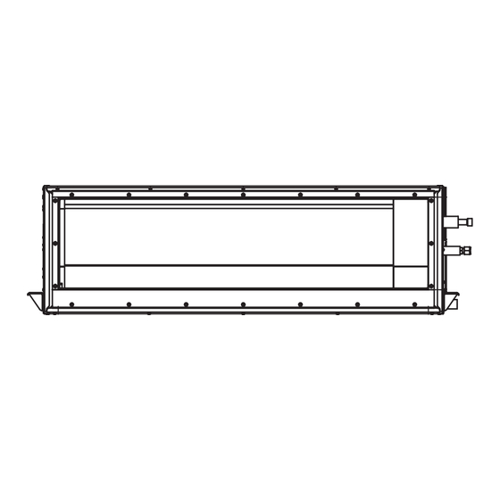
VRF Concealed Duct High Static Pressure air conditioner
Model name:
40VD____H-8S-TST
Notice:
quality and reliability standards, and to meet local regulations and market requirements.
All features and specifications are subject to change without prior notice.
is committed to continuously improving its products to ensure the highest
Installation
Manual
11 289 50 164
For commercial use
สํ า หรั บ ใช ง านเชิ ง พาณิ ช ย
English
Installation Manual
1
คู ม ื อ การติ ด ตั ้ ง
ภาษาไทย
30
Advertisement
Table of Contents

Related Manuals for Carrier 40VD H-8S-TST Series


Summary of Contents for Carrier 40VD H-8S-TST Series
- Page 1 11 289 50 164 VRF Concealed Duct High Static Pressure air conditioner For commercial use สํ า หรั บ ใช ง านเชิ ง พาณิ ช ย Model name: 40VD____H-8S-TST Installation Manual Notice: is committed to continuously improving its products to ensure the highest quality and reliability standards, and to meet local regulations and market requirements.
-
Page 2: Table Of Contents
– 1 – Original instruction Thank you for purchasing this air conditioner. Please read carefully through these instructions that contain important information and ensure that you understand them. Please read this Installation Manual carefully before installing the Air Conditioner. After completing the installation work, hand over this Installation Manual as well as the Owner’s Manual provided •... -
Page 3: Warning Indications On The Air Conditioner Unit
Definition of Protective Gear Warning indications on the air conditioner unit When the air conditioner is to be transported, installed, maintained, repaired or removed, wear protective gloves and ‘Safety’ work clothing. In addition to such normal protective gear, wear the protective gear described below when undertaking the special Warning indication Description work detailed in the following table. -
Page 4: Precautions For Safety
– 3 – • Only a qualified installer(*1) or qualified service person(*1) is Precautions for safety allowed to undertake work at heights using a stand of 50 cm or The manufacturer shall not assume any liability for the damage more or to remove the intake grille of the indoor unit to undertake caused by not observing the description of this manual. -
Page 5: Selection Of Installation Location
• When the air conditioner must be transported by hand, carry it by Installation four or more people. • Suction duct length must be longer than 850 mm. • Do not move or repair any unit by yourself. There is high voltage •... -
Page 6: Electrical Wiring
– 5 – • Tighten the flare nut with a torque wrench in the specified • Do not connect earth wires to gas pipes, water pipes, and manner. Excessive tighten of the flare nut may cause a crack in lightning conductor or telephone earth wires. the flare nut after a long period, which may result in refrigerant •... -
Page 7: New Refrigerant Air Conditioner Installation
• After the work has finished, use an insulation tester set CAUTION (500V Megger) to check the resistance is 1MΩ or more between New refrigerant air conditioner installation the charge section and the non-charge metal section • This air conditioner adopts the new HFC refrigerant (R410A) (Earth section). -
Page 8: Accessory Parts
– 7 – Accessory parts Selection of installation place Accessory parts Avoid installing in the following places Select a location for the indoor unit where the cool or warm air will circulate evenly. Avoid installation in the following kinds of locations. Part name Q’ty Shape... -
Page 9: Installation Space
Installation under high-humidity atmosphere Installation space (Unit: mm) In some cases including the rainy season, especially inside of the ceiling may become high-humidity atmosphere Reserve sufficient space required for installation or service work. (dew-point temperature: 23 °C or higher). Space required for installation and servicing 1. -
Page 10: Installation
– 9 – Installation of hanging bolt Installation of indoor unit Installation Consider the piping / wiring after the unit is hung to Treatment of ceiling CAUTION determine the location of the indoor unit installation The ceiling differs according to structure of building. and orientation. -
Page 11: Drain Piping
REQUIREMENT Drain piping Removing the cardboard for transportation CAUTION Make sure to remove the protection cardboard for transportation that is inserted in the gap between the top cabinet and the heat exchanger before installing the indoor unit. Following the Installation Manual, perform the drain piping work so that water is properly drained. Apply a heat insulation so as not to cause a dew condensation. -
Page 12: Connecting Drain Pipe
– 11 – Connecting drain pipe Heat insulating process Insert flexible drain hose into the drain pipe of main unit as far as it will go. Fix it with hose band. As shown in the figure, cover the flexible hose and hose band with the attached heat insulator up to the bottom of the indoor unit tightly. -
Page 13: Fan Characteristics
Fan characteristics 072H type 096H type Standard Air Flow : 3800 (m³/h) Standard Air Flow : 4800 (m³/h) Mid(250Pa) Mid(217Pa) Mid(250Pa) High(250Pa) Mid(183Pa) Mid(217Pa) High(217Pa) Mid(150Pa,117Pa) Mid(183Pa) High(183Pa) Mid(150Pa,117Pa) High(250Pa) High(150Pa) High(217Pa) High(117Pa) High(183Pa) High(83Pa) High(150Pa) High(50Pa) High(117Pa) High(83Pa) High(50Pa) Mid(83Pa) Mid(83Pa) Mid(50Pa) -
Page 14: Duct Design
– 13 – Duct design Duct design Arrangement (Unit: mm) Referring to the following dimensions, manufacture duct at the local site. In order to prevent short circuits, design (Thickness of plate : 0.8 mm) the duct work so that the intake and discharge openings are not adjacent to <Air outlet>... -
Page 15: Refrigerant Piping
Refrigerant piping Tightening connection CAUTION CAUTION Do not burn the pipe heat insulator. Refrigerant piping Flaring Be careful for the flame, due to the brazing Do not apply excessive torque. Otherwise, the Cut the pipe with a pipe cutter. process on the ceiling. nut may crack depending on the conditions. -
Page 16: Electrical Connection
– 15 – Refrigerant amount to be added Heat insulation process Electrical connection For addition of the refrigerant, add refrigerant “R410A” Apply heat insulation for the pipes separately at liquid referring to the attached Installation Manual of outdoor side and gas side. Power supply wire and unit. - Page 17 Power supply [Uh line] L1 = Up to 2000 m Power supply 220V ~, 50 Hz Power supply switch/circuit breaker or power supply wiring/fuse rating for indoor units should be selected by the [Uv and Uc line] accumulated total current values of the indoor units. L2 = Up to 1000 m Below 20 m 2.5 mm²...
-
Page 18: Wiring Example
– 17 – Remote controller wiring Wiring between indoor unit and outdoor unit 2-core with non-polarity wire is used for wiring of the remote controller wiring and group remote controllers wiring. Remote controller wiring, remote controller inter-unit NOTE Wire size: 0.5 mm² to 2.0 mm² wiring An outdoor unit that is interconnected to the indoor units automatically becomes the header unit. -
Page 19: Wire Connection
Wire connection Remote controller wiring Strip off approx. 9 mm the wire to be connected. REQUIREMENT Wiring diagram Connect the wires matching the terminal numbers. Incorrect connection causes a trouble. Pass the wires through the bushing of wire connection holes of the indoor unit. Keep a margin (Approx. -
Page 20: Applicable Controls
– 19 – External static pressure Applicable controls Each time [ ] setting button is pushed, indoor unit numbers in the group settings control change cyclically. Select the indoor Applicable controls setup REQUIREMENT unit to change settings for. To set the external static pressure, refer to the (settings at the site) The fan of the selected indoor unit runs. -
Page 21: Filter Sign Setting
Filter sign setting Group control <Setting up on the circuit board of the indoor unit> To set up the external static pressure, use the DIP switch on the circuit board of the wireless reception part. For details, refer to the instruction manual of the wireless remote controller kit. Alternatively, use the switch on the According to the installation condition, the filter sign In a group control, a remote controller can control up indoor micro computer circuit board as shown in the following figure and table. -
Page 22: Test Run
– 21 – Wired remote controller Test run Be sure to stop the air conditioner before making settings. Before test run Execute a test run (Change the setup while the air conditioner is not working.) Before turning on the power supply, carry out the When a fan operation is to be performed for an following procedure. -
Page 23: Maintenance
Maintenance Periodic Maintenance For environmental conservation, it is strongly recommended that the indoor and outdoor units of the air conditioner in use be cleaned and maintained regularly to ensure efficient operation of the air conditioner. When the air conditioner is operated for a long time, periodic maintenance (once a year) is recommended. CAUTION Furthermore, regularly check the outdoor unit for rust and scratches, and remove them or apply rustproof treatment, if necessary. -
Page 24: Troubleshooting
– 23 – Troubleshooting Confi rmation and check If a problem occurs with the air conditioner, the OFF timer indicator alternately shows the check code and the indoor Unit No. in which the problem occurred. Check code The indoor Unit No. in which the problem occurred. -
Page 25: Check Method
Check method On the wired remote controller, central control remote controller and the interface P.C. Board of the outdoor unit (I/F), a check display LCD (Remote controller) or 7-segment display (on the outdoor interface P.C. Board) to display the operation is provided. - Page 26 – 25 – Check code Wireless remote controller Outdoor unit 7-segment display Sensor block display of receiving unit Check code name Judging device Wired remote controller display Auxiliary code Operation Timer Ready Flash 01: TE1 sensor 02: TE2 sensor TE1,TE2 or TE3 sensor trouble 03: TE3 sensor 01: TL1 sensor 02: TL2 sensor...
- Page 27 Check code Wireless remote controller Outdoor unit 7-segment display Sensor block display of receiving unit Check code name Judging device Wired remote controller display Auxiliary code Operation Timer Ready Flash ─ Model mismatch of indoor and outdoor unit ─ ─ Indoor unit centre unit duplicated Indoor unit ─...
- Page 28 – 27 – Check code Wireless remote controller Outdoor unit 7-segment display Sensor block display of receiving unit Check code name Judging device Wired remote controller display Auxiliary code Operation Timer Ready Flash 01: Comp. 1 side 02: Comp. 2 side IPM short protection trouble Inverter 03: Comp.
-
Page 29: Warnings On Refrigerant Leakage
Warnings on Refrigerant Leakage Important 2) When there is an effective opening with the adjacent room for ventilation of leaking refrigerant gas Check of concentration limit (opening without a door, or an opening 0.15% or larger than the respective floor spaces at the top or bottom of the door). - Page 30 – 29 –...
- Page 31 คํ า แนะนํ า เบื ้ อ งต น ขอบคุ ณ ที ่ เ ลื อ กซื ้ อ เคร องปรั บ อากาศ โปรดอ า นคํ า แนะนํ า ต า งๆ ที ่ ม ี ข อ มู ล สํ า คั ญ และโปรดปฏิ บ ั ต ิ ต ามข อ มู ล ดั ง กล า ว หลั...
- Page 32 – 31 – คํ า อธิ บ ายอุ ป กรณ ป อ งกั น สั ญ ลั ก ษณ ค ํ า เตื อ นของตั ว เครองปรั บ อากาศ สวมถุ ง มื อ ป อ งกั น และชุ ด ที ่ ป ลอดภั ย สํ า หรั บ การทํ า งาน เม อเคล อนย า ย ติ ด ตั ้ ง บํ า รุ ง รั ก ษาซ อ มแซม หรื อ ถอดชิ ้ น ส ว น เคร...
-
Page 33: ข อ ควรระวั ง เพอความปลอดภั ย
ข อ ควรระวั ง เพอความปลอดภั ย สวมถุ ง มื อ ป อ งกั น และเสื ้ อ ผ า ที ่ ป ลอดภั ย สํ า หรั บ การทํ า งานขณะทํ า การติ ด ตั ้ ง ซ อ มแซม หรื อ ถอดชิ ้ น ส ว น ผู... - Page 34 – 33 – การเลื อ กสถานที ่ เ พื ่ อ ทํ า การติ ด ตั ้ ง การติ ด ตั ้ ง หากติ ด ตั ้ ง เครองปรั บ อากาศในห อ งขนาดเล็ ก ปฏิ บ ั ต ิ ต ามมาตรการที ่ เ หมาะสมเพอ ความยาวของท...
- Page 35 ขั น แฟร น ั ท ให แ นนด ว ยประแจวั ด แรงบิ ด ตามวิ ธ ี ท ี ่ ก ํ า หนดไว หากขั น แฟร น ั ท แนน ห า มต อ สายดิ น กั บ ท อ ก า ซ ท อ นํ ้ า และสายล อ ฟ า หรื อ สายดิ น ของโทรศั พ ท เกิ...
- Page 36 – 35 – หลั ง จากเสร็ จ งานแล ว ให ใ ช ช ุ ด อุ ป กรณ ท ดสอบฉนวน (แรงดั น ไฟฟ า 500V) ข อ ควรระวั ง ตรวจสอบว า ความต า นทานระหว า งส ว นที ่ ม ี ป ระจุ ก ั บ ส ว นโลหะที ่ ไ ม ม ี ป ระจุ (ส ว นดิ น ) การติ...
- Page 37 ชิ ้ น ส ว นอุ ป กรณ เ สริ ม การเลื อ กสถานที ่ ต ิ ด ตั ้ ง ชิ ้ น ส ว นอุ ป กรณ เ สริ ม หลี ก เลี ่ ย งการติ ด ตั ้ ง ในบริ เ วณต อ ไปนี ้ เลื...
- Page 38 – 37 – การติ ด ตั ้ ง ในสภาวะที ่ ม ี ค วามชื ้ น สู ง พื ้ น ที ่ ต ิ ด ตั ้ ง (หนวย: mm) ในบางกรณี ร วมถึ ง ช ว งฤดู ฝ นโดยเฉพาะอย า งยิ ่ ง ด า นในของเพดานอาจมี ส ภาวะที ่ ม ี ค วามชื ้ น สู ง สํ...
- Page 39 การติ ด ตั ้ ง การติ ด ตั ้ ง สลั ก สํ า หรั บ แขวน การติ ด ตั ้ ง เครองภายใน ขณะที ่ ท ํ า การกํ า หนดตํ า แหนงและทิ ศ ทางที ่ จ ะแขวน การดู แ ลรั ก ษาฝ า เพดาน ข...
- Page 40 – 39 – การต อ ท อ นํ ้ า ทิ ้ ง ข อ กํ า หนด การนํ า แผ น กั น กระแทกออกเพอการเคลอนย า ย ข อ ควรระวั ง ให แ นใจว า ได ถ อดแผ น กั น กระแทกออกป อ งกั น สํ า หรั บ การเคลอนย า ยที ่ ส อดในช อ งว า งระหว า งโครงด า นบนและตั ว แลกเปลี ่ ย น ต...
- Page 41 การต อ ท อ ระบายนํ ้ า ขั ้ น ตอนการใช ฉ นวนกั น ความร อ น สอดท อ อ อ นระบายนํ ้ า เข า ไปในท อ นํ ้ า ทิ ้ ง ของตั ว เครื ่ อ งหลั ก ให ล ึ ก ที ่ ส ุ ด เท า ที ่ ท ํ า ได ยึ ด ให แ น น ด ว ยสายรั ด ท อ ควรคลุ...
- Page 42 – 41 – คุ ณ ลั ก ษณะการทํ า งานของพั ด ลม ประเภท 072H ประเภท 096H ปริ ม าณอากาศมาตรฐาน : ปริ ม าณอากาศมาตรฐาน : 3800 (m³/h) 4800 (m³/h) กลาง(250Pa) กลาง(217Pa กลาง(250Pa) สู ง (250Pa) กลาง(183Pa) กลาง(217Pa) สู ง (217Pa) กลาง(150Pa,117Pa) กลาง(183Pa) สู...
- Page 43 การออกแบบท อ ลม การออกแบบท อ ลม การจั ด เตรี ย ม (หนวย: mm) โปรดอ า งอิ ง ขนาดต อ ไปนี ้ จั ด ทํ า ท อ ลมในสถานที ่ ต ิ ด ตั ้ ง เพ อป อ งกั น ไม ใ ห เ กิ ด การลั ด วงจร ให ท ํ า การ (ความหนาของแผ...
- Page 44 – 43 – การต อ ท อ ส ง สารทํ า ความเย็ น การเช อมต อ แบบขั น แนน ข อ ควรระวั ง ข อ ควรระวั ง ห า มทํ า ให ฉ นวนกั น ความร อ นของท อ ไหม การต...
-
Page 45: การต อ สายไฟ
การต อ สายไฟ ปริ ม าณสารทํ า ความเย็ น ที ่ จ ะเติ ม ขั ้ น ตอนการใช ฉ นวนกั น ความร อ น สํ า หรั บ การเติ ม สารทํ า ความเย็ น ให เ ติ ม สารทํ า ความเย็ น ใช... - Page 46 – 45 – แหล ง จ า ยไฟ [สายไฟ Uh] L1 = สู ง สุ ด 2000 m แหล ง จ า ยไฟ 220V ~, 50 Hz ควรเลื อ กสวิ ต ช แ หล ง จ า ยไฟ/เครื ่ อ งตั ด กระแสไฟฟ า หรื อ สายไฟของแหล ง จ า ยไฟ/พิ ก ั ด ฟ ว ส ส ํ า หรั บ ตั ว เครื ่ อ งภายใน โดยใช ค า กระแสไฟ [สาย...
- Page 47 การเดิ น สายไฟรี โ มทคอนโทรล การเดิ น สายไฟระหว า งตั ว เครองภายในและตั ว เครองภายนอก สายไฟไม ม ี ข ั ้ ว แบบ 2 แกนใช ส ํ า หรั บ การเดิ น สายไฟรี โ มทคอนโทรลและเดิ น สายรี โ มทคอนโทรลแบบเป น กลุ ม การเดิ...
- Page 48 – 47 – การต อ สายไฟ การเดิ น สายไฟรี โ มทคอนโทรล ปอกฉนวนสายไฟออก 9 mm เพื ่ อ ทํ า การเชื ่ อ มต อ ข อ กํ า หนด เชอมต อ ต อ สายไฟเข า กั บ หมายเลขขั ้ ว ต อ ที ่ ถ ู ก ต อ ง หากต อ ผิ ด อาจเกิ ด ข อ ผิ ด พลาดได แผนผั...
- Page 49 การควบคุ ม การใช ง าน การตั ้ ง ค า แรงดั น สถิ ต ย ภ ายนอก แต ล ะครั ้ ง ที ่ ก ดปุ ม ตั ้ ง ค า [ ] [ ] จํ า นวนของ ตั...
- Page 50 – 49 – <การตั ้ ง ค า บนแผงวงจรของตั ว เครื ่ อ งภายใน> การตั ้ ง ค า สั ญ ญาณของแผ น กรอง การควบคุ ม แบบเป น กลุ ม ใช ส วิ ต ช DIP บนแผงวงจรของส ว นรั บ สั ญ ญาณไร ส ายเพื ่ อ ทํ า การตั ้ ง ค า แรงดั น คงที ่ ภ ายนอก สํ...
- Page 51 การทดสอบการทํ า งาน รี โ มทคอนโทรลแบบมี ส าย ตรวจสอบให แ น ใ จว า ได ป ด เครื ่ อ งปรั บ อากาศก อ นทํ า การ ตั ้ ง ค า ก อ นทํ า การทดสอบการทํ า งาน ดํ...
- Page 52 – 51 – การบํ า รุ ง รั ก ษา การบํ า รุ ง รั ก ษาเครองตามช ว งเวลา เพื ่ อ ป อ งกั น ความสู ญ เสี ย จากสภาพแวดล อ ม ขอแนะนํ า ให ท า นทํ า ความสะอาด และบํ า รุ ง รั ก ษาตั ว เครื ่ อ งภายในและตั ว เครื ่ อ ง ภายนอกของเครื...
- Page 53 การแก ไ ขป ญ หา การยื น ยั น และตรวจสอบ หากเครื ่ อ งปรั บ อากาศมี ป ญ หา สั ญ ญาณ ตั ว ตั ้ ง เวลา OFF จะแสดงขึ ้ น สลั บ กั บ รหั ส ตรวจสอบและหมายเลขของ ตั...
- Page 54 – 53 – วิ ธ ี ก ารตรวจสอบ บนรี โ มทคอนโทรลแบบมี ส าย รี โ มทคอนโทรลควบคุ ม กลางและแผงวงจร P.C. อิ น เตอร เ ฟซของตั ว เครื ่ อ งภายนอก (I/F) การตรวจสอบจะแสดง LCD (รี โ มทคอนโทรล) หรื อ หน า จอแสดงผลแบบ 7 ส ว น (บนแผงวงจร P.C. อิ น เตอร เ ฟซภายนอก) เพื ่ อ แสดงการทํ า งาน ดั...
- Page 55 รหั ส การตรวจสอบ รี โ มทคอนโทรลแบบไร ส าย หน า จอแสดงผลแบบ 7 ส ว นของตั ว เคร องภายนอก หน า จอบล็ อ กเซนเซอร ข องตั ว รั บ สั ญ ญาณ ช อรหั ส การตรวจสอบ เคร องมื อ ตั ด สิ น หน...
- Page 56 – 55 – รหั ส การตรวจสอบ รี โ มทคอนโทรลแบบไร ส าย หน า จอแสดงผลแบบ 7 ส ว นของตั ว เคร องภายนอก หน า จอบล็ อ กเซนเซอร ข องตั ว รั บ สั ญ ญาณ ช อรหั ส การตรวจสอบ เคร องมื อ ตั ด สิ น หน...
- Page 57 รหั ส การตรวจสอบ รี โ มทคอนโทรลแบบไร ส าย หน า จอแสดงผลของ หน า จอแสดงผลแบบ 7 ส ว นของตั ว เคร องภายนอก หน า จอบล็ อ กเซนเซอร ข องตั ว รั บ สั ญ ญาณ ช อรหั ส การตรวจสอบ เคร องมื อ ตั ด สิ น รี...
- Page 58 – 57 – คํ า เตื อ นเกี ่ ย วกั บ การรั ่ ว ไหลของสารทํ า ความเย็ น ข อ สํ า คั ญ 2) เมื ่ อ มี ก ารเป ด ช อ งไปยั ง ห อ งที ่ อ ยู ต ิ ด กั น อย า งมี ป ระสิ ท ธิ ภ าพเพื ่ อ การระบายก า ซสารทํ า ความเย็ น ที ่ ร ั ่ ว ไหล (ช อ งเป ด ที ่ ไ ม ใ ช ตรวจสอบค...
- Page 59 – 58 –...
- Page 60 Installation Manual Model name: 40VD____H-8S-TST 1 1 2 8 9 5 0 1 6 4...
Need help?
Do you have a question about the 40VD H-8S-TST Series and is the answer not in the manual?
Questions and answers