Table of Contents
Advertisement
Quick Links
Advertisement
Table of Contents

Related Manuals for MicroTouch M1 Series


Summary of Contents for MicroTouch M1 Series
- Page 1 USER MANUAL MicroTouch All-In-One PC M1 Series Windows Touch Computer...
-
Page 2: About This Document
Microtouch. The information in this document is subject to change without notice. Microtouch makes no representations or warranties with respect to the contents herein, and specifically disclaims any implied warranties of merchantability or fitness for a particular purpose. -
Page 3: Table Of Contents
User’s Manual User’s Manual Table of contents Introduction ................2 Package of contents .............3 Safety and regulatory information ........5 Safety..........................5 Installation ..............................6 Use ................................. 7 Regulatory compliance ....................8 For FCC (USA) ............................8 For IC (Canada) ............................8 For CE (EU) ..............................8 For UL/cUL (USA/Canada) ........................ - Page 4 User’s Manual User’s Manual Barcode scanner (optional) ..................26 Installing the barcode scanner ......................26 Removing the barcode scanner ......................27 Camera module (optional) ..................28 Installing the camera module ......................28 Removing the camera module ......................29 Light bar (optional) ....................31 Installing the light bar ...........................31 Removing the light bar .........................32 Magnetic stripe reader (MSR) module (optional) ..........33 Installing the MSR module ........................33...
-
Page 5: Safety And Regulatory Information
User’s Manual User’s Manual Safety and regulatory information Safety WARNING: To avoid risk of electric shock, this equipment must only be connected to a supply mains with protective earth. WARNING: To prevent the risk of fire or shock hazards, and do not expose the product to moisture. General recommendations •... -
Page 6: Moisture Condensation
User’s Manual User’s Manual Mission critical applications We strongly recommend there is a replacement device immediately available in mission critical applications. Transient over-voltage To fully disengage the power to the device, please disconnect the adapter from the AC inlet. Liquids and moisture •... -
Page 7: Use
User’s Manual User’s Manual General warnings: • The enclosure has to be checked upon collision damage, refer to qualified service personnel. • The protective screen (if present) is made of tested high-resistance glass. Nonetheless there is the possibility that it may crack if subject to strong impacts. Evaluate and prevent the risk of possible breakages of the protective screen by correctly handling and positioning the device. -
Page 8: Regulatory Compliance
User’s Manual User’s Manual Regulatory compliance For FCC (USA) Notice to Users in the United States: This equipment has been tested and found to comply with the limits for a Class B digital device, pursuant to Part 15 of FCC Rules. These limits are designed to provide reasonable protection against harmful interference in a residential installation. -
Page 9: General Information
User’s Manual User’s Manual General information In this section, you will find information on the package content and device’s features. Package content Unpacking • Before unpacking your device, find a location near a wall outlet and be easily accessible. • Set the device box in an upright position and open from the top of the box before removing the top cushions. -
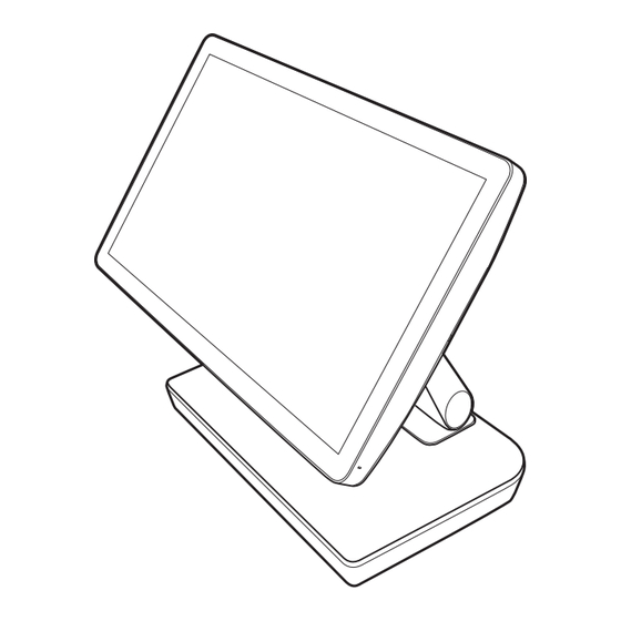
Page 10: Product Overview
User’s Manual User’s Manual Product overview Front view NOTE: The device can be purchased with the stand including the hub (image above) or without the hub. Function Description Display screen with multi-touch functionality. Display screen NOTE: This device supports finger/glove touch method. Device status indicator. -
Page 11: Rear View
User’s Manual User’s Manual Rear view LINE OUT HDMI RJ45 USB 3.0 USB 3.0 DC IN USB-C USB-C LINE OUT HDMI RJ45 USB-Type A USB-Type A USB-C2 USB-C1 Power 10 11 COM2 COM1 Cash Drawer PUSB12V PUSB24V USB 3.0 USB-C 24V Out 24V In 14 15... - Page 12 User’s Manual User’s Manual Function Description Connect peripherals to the device. LINE OUT connector Connect with audio line-out devices. HDMI connector Connect with HDMI compatible devices. RJ45 connector Connect the device to the Internet via RJ45 cable. USB 3.0 connectors (x4) Connect with USB 3.0 compatible devices.
-
Page 13: Setup And Installation
User’s Manual User’s Manual Setup and installation In this section, you will find information on how to remove and install the stand, adjust the viewing angle, wall mount the device, and more. Replacing the stand NOTE: The stand is pre-installed to the device. Removing the stand (without hub) To remove the stand without the hub, do the following: Place the device on a flat surface, with the screen facing down. -
Page 14: Installing The Stand (Without Hub)
User’s Manual User’s Manual Installing the stand (without hub) To install the stand without the hub, do the following: Place the device on a flat surface, with the screen facing down. NOTE: We recommend to cover the surface with soft cloth to prevent damage to the screen of the device. -
Page 15: Removing The Stand (With Hub)
User’s Manual User’s Manual Removing the stand (with hub) To remove the stand with the hub, do the following: Place the device on a flat surface, with the screen facing down. NOTE: We recommend to cover the surface with soft cloth to prevent damage to the screen of the device. -
Page 16: Installing The Stand (With Hub)
User’s Manual User’s Manual Remove the four (4) screws securing the stand to the device. Remove the stand. Installing the stand (with hub) To install the stand with the hub, do the following: Place the device on a flat surface, with the screen facing down. NOTE: We recommend to cover the surface with soft cloth to prevent damage to the screen of the device. - Page 17 User’s Manual User’s Manual Route the power cable through the opening on the stand and then through the cable clip. Connect and secure the power cable to the power connector of the device. Install the upper cable cover to the device and press on it firmly to secure the latches (marked with gray circles).
-
Page 18: Routing The Cables
User’s Manual User’s Manual Routing the cables Routing the cables (stand without hub) To route the power and HDMI cables, do the following: Place the device on a flat surface, with the screen facing down. NOTE: We recommend to cover the surface with soft cloth to prevent damage to the screen of the device. - Page 19 User’s Manual User’s Manual Route the power and HDMI cables through the opening on the bottom of the stand. Continue routing them through the cable clips on top of the stand. Connect the power cable to the power connector of the device. Connect the HDMI cable to the HDMI connector of the device.
-
Page 20: Routing The Cables (Stand With Hub)
User’s Manual User’s Manual Install the cable cover to the stand and press on it firmly to secure the latches (marked with gray circles). Install the upper cable covers to the device and press on them firmly to secure the latches (marked with gray circles). - Page 21 User’s Manual User’s Manual Connect the USB cable to the USB connector of the hub. Route the HDMI cable through the opening on the bottom of the stand. Continue routing it through the cable clip on top of the stand. Connect the HDMI cable to the HDMI connector of the device.
- Page 22 User’s Manual User’s Manual Install the cable cover to the stand and press on it firmly to secure the latches (marked with gray circles). Install the upper cable covers to the device and press on them firmly to secure the latches (marked with gray circles).
-
Page 23: Adjusting The Viewing Angle
User’s Manual User’s Manual Adjusting the viewing angle To adjust the viewing angle, do the following: Place the device in an upright position on a flat, stable surface. Adjust the angle of the screen. The angle of the screen can be adjusted forwards and backwards up to 170°... -
Page 24: Wall Mounting
User’s Manual User’s Manual Wall mounting This device supports VESA standard mount with 100mm x 100mm pattern located at the rear of the device. NOTE: • Before mounting the device on the wall, remove the stand (refer to “Removing the stand (without hub)”... -
Page 25: Removing The Peripheral Compartment Cover
User’s Manual User’s Manual Before installing the optional accessory, remove the selected compartment’s cover. After removing the optional accessory, replace the compartment cover. Removing the peripheral compartment cover Before installing the optional accessory, remove the selected peripheral compartment cover. For example, the compartment cover on the right side: Installing the peripheral compartment cover After removing the optional accessory, replace the peripheral compartment cover. -
Page 26: Barcode Scanner (Optional)
User’s Manual User’s Manual Barcode scanner (optional) Installing the barcode scanner To install the barcode scanner, do the following: Remove the peripheral compartment cover. Refer to page 25. Align and connect the barcode scanner to the device. Attach the mylar pad on each screw. Secure the barcode scanner to the device with the two (2) screws. -
Page 27: Removing The Barcode Scanner
User’s Manual User’s Manual Adjust the laser beam position, either upwards or downwards. • Laser beam is pointing upwards: • Laser beam is pointing downwards: Turn the lock on the barcode reader clockwise to secure the laser beam position. Removing the barcode scanner To remove the barcode scanner, do the following: Detach the mylar pads from the two (2) screws. -
Page 28: Camera Module (Optional)
User’s Manual User’s Manual Disconnect the barcode scanner from the device. Replace the peripheral compartment cover. Refer to page 25. Camera module (optional) Installing the camera module To install the camera module, do the following: Remove the peripheral compartment cover. Refer to page 25. Align and connect the camera module to the device. -
Page 29: Removing The Camera Module
User’s Manual User’s Manual Secure the camera module to the device with the two (2) screws. Attach the mylar pad on each screw. Push the camera module forward to face the front of the device. Removing the camera module To remove the camera module, do the following: Push the camera module backwards until it is flush with its holder. - Page 30 User’s Manual User’s Manual Detach the mylar pads from the two (2) screws. Remove the two (2) screw securing the camera module to the device. Disconnect the camera module from the device. Replace the peripheral compartment cover. Refer to page 25. General information...
-
Page 31: Light Bar (Optional)
User’s Manual User’s Manual Light bar (optional) Installing the light bar To install the light bar, do the following: Remove the peripheral compartment cover. Refer to page 25. Align and connect the light bar to the device. Secure the light bar to the device with the two (2) screws. Attach the mylar pad on each screw. -
Page 32: Removing The Light Bar
User’s Manual User’s Manual Removing the light bar To remove the light bar, do the following: Detach the mylar pads from the two (2) screws. Remove the two (2) screw securing the light bar to the device. Disconnect the light bar from the device. Replace the peripheral compartment cover. -
Page 33: Magnetic Stripe Reader (Msr) Module (Optional)
User’s Manual User’s Manual Magnetic stripe reader (MSR) module (optional) Installing the MSR module To install the MSR module, do the following: Remove the peripheral compartment cover. Refer to page 25. Align and connect the MSR module to the device. Secure the MSR module to the device with the two (2) screws. -
Page 34: Removing The Msr Module
User’s Manual User’s Manual Removing the MSR module To remove the MSR module, do the following: Detach the mylar pads from the two (2) screws. Remove the two (2) screw securing the MSR module to the device. Disconnect the MSR module from the device. Replace the peripheral compartment cover. -
Page 35: Appendix
Item IDC-151 IDC-221 M1-156P-W3-A1 / M1-215P-W3-A1/ MT model number M1-156P-W3-A2 (with stand) M1-215P-W3-A2 (with stand) Version 1.00 1.00 Microtouch model IDC-151J5003G1F001 / IDC-221J5002G1F001 / number IDC-151J7003G1F002 IDC-221J7002G1F002 SAP part number Size 15.6” TFT LCD 21.5” TFT LCD Maximum resolution 1920 x 1080... - Page 36 User’s Manual User’s Manual Description Item IDC-151 IDC-221 IO ports on stand with the hub: 1 x 24V PSUB 1 x 24V PSUB 2 x 12V PSUB 2 x 12V PSUB USB port 8 x USB 3.0 USB-A 8 x USB 3.0 USB-A 1 x USB-C PD ouput 1 x USB-C PD ouput Serial port...
-
Page 37: Peripherals Specification
User’s Manual User’s Manual Peripherals specification MSR module Item Description MT model number MA-MSR-A1 Swipe speed ISO standard card: 5-60 ips Swipe direction Bi-directional Number of tracks Reads up to 3 tracks (supports TDES encryption with DUKPT key management) Power supply +5VDC, +/-5% Power consumption (typical) 7mA (maximum) -
Page 38: Camera Module
User’s Manual User’s Manual Camera module Item Description MT model number MA-CAM-A1 Resolution 3264 x 2448 (8M) @15fps FHD 1920 x 1080 @30fps OS support Windows 10/ Android Compliance RoHS, REACH Module specification Dimension 111.3 x 68.1 x 18 (mm) Net weight Lens specification Lens composition... -
Page 39: Light Bar
User’s Manual User’s Manual Item Description Resolution 1D 3 mil Standard+V11:W27d Presentation mode configuration • USB HID Keyboard Mode • Supported terminal modes USB Serial Mode • HID POS Mode Directly to: • M1-156DT-A1 Compatibility • M1-215DT-A1 • M1-238DT-A1 Illumination & aiming 3000K LED &... -
Page 40: Dimensions
User’s Manual User’s Manual Dimensions IDC-151 (without hub) Appendix... -
Page 41: M1-151 (With Hub)
User’s Manual User’s Manual IDC-151 (with hub) Appendix... -
Page 42: M1-215 (Without Hub)
User’s Manual User’s Manual IDC-221 (without hub) Appendix... -
Page 43: M1-215 (With Hub)
User’s Manual User’s Manual IDC-221 (with hub) Appendix... -
Page 44: Troubleshooting
User’s Manual User’s Manual Troubleshooting This section describes some common problems that you may experience when using the device and provides some general guidelines and solutions for troubleshooting. If the suggested solutions fail to resolve the problem, please contact your dealer or our service center. -
Page 45: Maintenance
The device does not require any routine maintenance other than occasional cleaning the areas of the device. We recommend cleaning every two weeks. All the maintenance and repair should operate by a qualified, factory-trained technician. In any case of doubts, please contact Microtouch service center. Cleaning Enclosure: •...
Need help?
Do you have a question about the M1 Series and is the answer not in the manual?
Questions and answers