Table of Contents
Advertisement
Quick Links
Advertisement
Table of Contents

Related Manuals for MicroTouch IC-100P-AA1


Summary of Contents for MicroTouch IC-100P-AA1
- Page 1 User Manual IC-100P-AA1 Interactive Computer...
- Page 2 MicroTouch a TES Company. The information in this document is subject to change without notice. MicroTouch TES Company makes no representations or warranties with respect to the contents herein, and specifically disclaims any implied warranties of merchantability or fitness for a particular purpose.
- Page 3 Compliance Information For FCC (USA) This equipment has been tested and fund to comply with the limits for a Class A digital device, pursuant to part 15 of the FCC Rules. There limits are designed to provide reasonable protection against harmful interference when the equipment is operated in a commercial environment.
- Page 4 Renseignements relatifs à la conformité Pour la FCC (États-Unis). Ce matériel a fait l’objet d’essais qui ont déterminé qu’il respectait les limites d’un appareil de classe A selon la partie 15 des règlements de la FCC. Ces limites sont établies pour assurer une protection raisonnable contre les parasites nuisant à...
- Page 5 Usage Notice Warning - To prevent the risk of fire or shock hazards, and do not expose the product to moisture. Warning - Please do not open or disassemble the product as this may cause electric shock. Warning - Power cord shall be connected to a socket-outlet with earthing connection.
- Page 6 Avis d’utilisation Mise en garde — Pour prévenir les risques d’incendie ou d’électrocution, ne pas exposer le produit à l’humidité. Mise en garde — Prière de ne pas ouvrir ou démonter le produit, car cela pourrait entraîner l’électrocution. Mise en garde – Le cordon d’alimentation doit être branché à une prise pourvue d’une mise à...
-
Page 7: Table Of Contents
Table of Contents Chapter 1 ........................8 1.1 Overview ........................9 1.2 Feature ........................9 1.3 Specifications ......................9 1.4 Block Diagram ......................11 1.5 Interface Connectors ....................12 1.6 Package Overview ....................14 Chapter 2 ........................16 2.1 About VESA Mount ....................17 2.2 About Wall Mount ..................... - Page 8 Declaration of the Presence Condition of the Restricted Substances Marking ....51...
-
Page 9: Chapter 1
Chapter 1 Product Introduction... -
Page 10: Overview
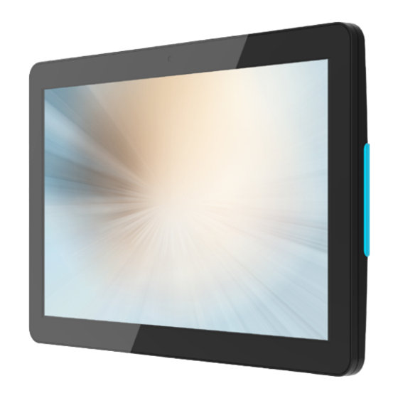
1.1 Overview The IC-100P-AA1 series is a thinner 10.1” touch panel pc that offers a unique screw less design with expandability and flexibility, making expansion and accessory installation much easier. The versatility of IC-100P-AA1 series is an exceptional choice for applications in all business sectors, especially in the retail market. - Page 11 Wi-Fi 802.11a/b/g/n 1T1R Bluetooth 4.0 (Support BLE) 1 x TF slot (Support SDHC 2.0) 1 x LAN (Support 10/100/1000Mbps, POE (802.3at 25W)) External IO Ports 1 x HDMI Type-C (Support 4K@60Hz) 1 x USB2.0 Type-A 1 x USB2.0 Type-C OTG (5V/0.5A) OS Version Android 8.1 Operation Temp.
-
Page 12: Block Diagram
1.4 Block Diagram... -
Page 13: Interface Connectors
1.5 Interface Connectors 12V DC in Pin # Signal Name Pin # Signal Name RJ45 for LAN Pin # Signal Name Pin # Signal Name TP1+ TP1- TP2+ TP3- TP3+ TP2- TP4+ TP4- Function Color Left Active Yellow (Blink) Right 10M/100M/1000M Green USB2.0... - Page 14 USB-C Pin # Signal Name Pin # Signal Name VBUS VBUS VBUS VBUS HDMI-C Pin # Signal Name Pin # Signal Name TMDS Data2 Shield TMDS Data2+ TMDS Data2- TMDS Data1 Shield TMDS Data1+ TMDS Data1- TMDS Data0 Shield TMDS Data0+ TMDS Data0- TMDS Clock Shield TMDS Clock+...
-
Page 15: Package Overview
This product is intended to be supplied by a UL Listed Power Adapter, rated 12Vdc, 2A maximum. (complied with LPS or PS2) T-ambient = 40 degree C minimum, and the altitude of operation = 3048m minimum. If it needs further assistance with purchasing the power source, please contact to MicroTouch for further information. - Page 16 12Vdc, 2A maximum. ( conforme au LPS ou PS2 ) T-ambient = 40 degrés C minimum et l’altitude de l’utilisation = 3048m minimum. Pour d’autres conseils pour l’installation de la source d’alimentation, communiquer avec MicroTouch pour de plus amples renseignements.
-
Page 17: Chapter 2
Chapter 2 Product Installation... -
Page 18: About Vesa Mount
2.1 About VESA Mount The IC-100P-AA1 series conform to the “VESA Flat Display Mounting Interface Standard” which defines a physical mounting interface for touch panel pc, and corresponding with the standards of touch panel pc mounting devices, such as wall-mounted or pole-mounted. The VESA mount is located on the back of this unit. - Page 19 Mise en garde! Sélectionner les vis d’origine de MicroTouch! La distance entre la surface du couvercle arrière et le bas de l’orifice de la vis est de 5 mm (sans kit de montage mural). Utiliser quatre vis M4 de 5 mm de diamètre pour le montage de votre moniteur.
-
Page 20: About Wall Mount
2.2 About Wall Mount The IC-100P-AA1 series support wall mount and this touch panel pc can be mounted to the wooden, glass or concrete wall. Note: Please install/ dismantle the product when the computer system is in the shutdown state. - Page 21 Step 4: Install the touch panel pc on the hook of the wall mount kit. Wooden or concrete wall Step 5: Install the two M3 screws.
-
Page 22: Wall Mount B
2.2.2 Wall Mount B Step 1: Place the wall mount kit on the wall, and using the keyholes on the wall mount kit, mark the positions to drill the two holes. Step 2: Drill two holes in the wall. Step 3: Install the two screws (not supplied) into the wall but do not seat them fully, leave a gap between the screw head and the wall. - Page 23 Step 4: Connect the Ethernet cable and power cable to touch panel pc. Step 5: Hook the wall mount kit into the recess hole on the back of the touch panel pc. Step 5 Step 4 Step 6: Route cables through cable clips and fix it together using the supplied cable tie. Step 7: Install the two M3 screws.
- Page 24 Step 8: Slide the touch panel pc onto the screws Wooden or concrete wall...
-
Page 25: Wall Mount C
2.2.3 Wall Mount C Step 1: Clean the glass with rubbing alcohol and dry thoroughly. Step 2: Route cables through cable clips and fix it together using the supplied cable tie. Step 3: Remove the film from the adhesive tape and attach the wall mount kit to the glass. Note: Touch panel pc must be installed under the cable outlet and power outlet. - Page 26 Step 5: Put additional even pressure on bracket area using rollers. Wait 8~12 hours for adhesive to build. Glass Step 6: Connect the Ethernet cable and power cable to touch panel pc. Step 7: Install the touch panel pc on the hook of the wall mount kit. Step 7 Step 6 Glass...
- Page 27 Step 8: Install the two M3 screws.
-
Page 28: Power On / Off Switch
2.3 Power On / Off Switch Power On/Off Switch Function Description Power on Press the power button 2 sec Press the power button to enter sleep mode, and press again to Sleep resume from sleep Power off Press the power button 2 sec to power off... -
Page 29: Light Bar
2.4 Light Bar Light Light LED Color Green, Red, Blue LED Mode Static, Blink, Smart Fade... -
Page 30: Nfc
2.5 NFC... -
Page 31: Dimension
2.6 Dimension Front View Side View Rear View Bottom View... -
Page 32: Optional Accessory Installation
2.7 Optional Accessory Installation Note: Please install/ dismantle the product when the computer system is in the shutdown state. 2.7.1 Install the Adjustable Cable Hanging Kit Step 1: Insert the cable into the plunger and slide the gripper to the desired position. Press down this spring to adjust the position. - Page 33 Step 3: Clean the glass with rubbing alcohol and dry thoroughly. Remove the film from the adhesive tape and attach the wall mount kit to the glass. Glass Step 4: Press wall mount kit for 30 seconds. Glass...
- Page 34 Step 5: Put additional even pressure on bracket area using rollers. Wait 8~12 hours for adhesive to build. Glass Step 6: Connect the Ethernet cable and power cable to touch panel pc. Step 7: Route cables. Step 7 Step 6...
- Page 35 Step 8: Install the touch panel pc on the hook of the wall mount kit. Glass Step 9: Install the two M3 screws.
- Page 36 Step 10: Determine the length of the cable used to hang the touch panel pc. Step 11: Rings are installed to the ceiling using the three screws (not supplied). Step 10 Step 11 Glass...
- Page 37 Step 12: Adjust the cable to a proper length. Press down this spring to adjust the length. Glass...
- Page 38 Step 13: Finishing installation. Glass Glass...
-
Page 39: Chapter 3
Chapter 3 Operating System Setup... -
Page 40: Initial Turn-On
3.1 Initial Turn-On The initial setup of the operating system takes approximately 5-10 minutes. Additional time may be needed depending on touch panel pc hardware configuration and connected devices. To setup the Android OS for the touch panel pc, turn on the touch panel pc and follow the instructions on the screen. -
Page 42: Chapter 4
Chapter 4 LED Programmable Guide 4.1 App Main Interface... - Page 43 Test: click the button to switch the ON/OFF state of the light.
-
Page 44: Chapter 5
Chapter 5 NFC Programmable Guide 5.1 Operating Instructions... -
Page 45: Equipment Operation (No Identification Card Required)
The CardReaderTest app is divided into three parts: device operation, NTAG card reading and writing function, Mifare card reading and writing function. As shown in Figure 1: Figure 1 5.1.1 Equipment Operation (no identification card required) When the application starts, get the device Information of Version, SN and WorkMode at the same time. -
Page 46: Ntag Card Operation (Other Card Types Are Not Supported)
Set Active: Set the working mode to Active, take the initiative to obtain, and read the card number when the card is recognized, displayed on the page. Set Passive: Set the working mode to Passive, the card number cannot be recognized. -
Page 47: Mifare Card Operation (Other Card Types Are Not Supported)
Figure 3 5.1.3 Mifare Card Operation (other card types are not supported) Please obtain the keys of different key types of the tested Mifare card for testing. The factory-set key of all key types of Mifare card is FFFFFFFFFFFF. Note: All operations of Mifare card need to be in WorkMode is operated in Passive mode. - Page 48 Figure 4 Write Mifare information: In addition to the data in the read operation, the corresponding block data type needs to be filled in. The type is a hexadecimal number and is 32 bits. As shown in Figure 5: Figure 5...
-
Page 49: Project Api Description
5.2 Project API Description If WorkMode is Active, the thread will be started to read the device node file information regularly. Passive, Get on request. ICM351aManager.java class method description: Determine whether the data acquisition is successful. bt[6]==0x00 means data is successfully requested. -
Page 50: Mifare Card Operation
void getNtagInfo(String pageStr); ▪ NTAG block information writing void writeNtagInfo(String ntagInfo, String pageStr); ▪ Obtain the UID of the TypeA card: void getTypeAUid(); 5.2.3 Mifare Card Operation Read and write operations need to be in WorkMode is the Passive mode. ▪... -
Page 51: Appendix
Appendix... - Page 52 Declaration of the Presence Condition of the Restricted Substances Marking 設備名稱:觸控電腦 型號(型式):IC-100P-AA1 Equipment name: Touch Panel PC Type designation (Type): IC-100P-AA1 限用物質及其化學符號 Restricted substances and its chemical symbols 單元 Unit 六價鉻 多溴聯苯 多溴二苯醚 鉛 汞 鎘 Cadmium Hexavalent Polybrominated Polybrominated...
Need help?
Do you have a question about the IC-100P-AA1 and is the answer not in the manual?
Questions and answers