Cissell L36USS36G Maintenance Service Manual
75 lb. laundry dryer
Hide thumbs
Also See for L36USS36G:
- Owner's manual (78 pages) ,
- Installation & operation manual (37 pages) ,
- Owner's manual (74 pages)
Table of Contents
Advertisement
Quick Links
MANUFACTURING COMPANY
MAINTENANCE/SERVICE
L36USS36G
L36USD36G
L36USP36G
CISSELL MANUFACTURING COMPANY
HEADQUARTERS
831 SOUTH FIRST ST.
P.O. BOX 32270
LOUISVILLE, KY 40232-2270
THIS MANUAL MUST BE GIVEN TO THE EQUIPMENT OWNER.
MAN354M
MANUAL
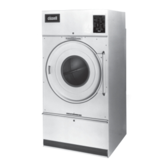
75 Lb. Laundry Dryer
GAS
L36URD36G
L36URS36G
L36URP36G
9/98
MODELS
STEAM
L36URS36S
L36URD36S
L36URP36S
PHONE: (502) 587-1292
SALES FAX: (502) 585-3625
SERVICE/PARTS FAX: (502) 681-1275
Page 1M
ELECTRIC
L36URS36E
L36URD36E
L36URP36E
D0562
Advertisement
Table of Contents
Troubleshooting

Related Manuals for Cissell L36USS36G


Summary of Contents for Cissell L36USS36G
- Page 1 L36USD36G L36URS36G L36URD36S L36URD36E L36USP36G L36URP36G L36URP36S L36URP36E CISSELL MANUFACTURING COMPANY HEADQUARTERS PHONE: (502) 587-1292 831 SOUTH FIRST ST. SALES FAX: (502) 585-3625 P.O. BOX 32270 SERVICE/PARTS FAX: (502) 681-1275 LOUISVILLE, KY 40232-2270 THIS MANUAL MUST BE GIVEN TO THE EQUIPMENT OWNER.
-
Page 2: For Your Safety
IMPORTANT NOTICES—PLEASE READ For optimum efficiency and safety, we recommend that you read the Manual before operating the equipment. Store this manual in a file or binder and keep for future reference. WARNING: For your safety, the information in this manual must be followed to minimize the risk of fire or explosion or to prevent property damage, personal injury, or loss of life. - Page 3 WARNING: Alterations to equipment may not be carried out without consulting with the factory and only by a qualified engineer or technician. Only Cissell parts may be used. WARNING: Remove clothes from dryer as soon as it stops. This keeps wrinkles from setting in and reduces the possibility of spontaneous combustion.
-
Page 4: Cissell Dryer Warranty
Cissell’s factory, transportation prepaid, within the applicable warranty period and found by Cissell to have been defective, and in no event shall Cissell be liable for damages of any kind, whether for any injury to persons or property or for any special or consequential damages. -
Page 5: Table Of Contents
TABLE OF CONTENTS 75 LB. LAUNDRY DRYER PAGE Model Numbers & Company Address ............................. 1M Important Notices ..................................2M-3M Dryer Warranty ....................................4M Table of Contents ..................................... 5M Warnings, Cautionary Notes and Symbols ..........................6M-7M Service Savers ....................................8M Troubleshooting ..................................9M-12M Norton Ignition System ................................ - Page 6 SYMBOLS The following symbols are used in this manual and/or on the machine. The numbers between () refer to the numbers on the machine surveys. Symbol D e s c r i p t i o n P a r t / M e a s u r e m e n t NOTE! Hot! Do Not Touch...
- Page 7 SYMBOLS Symbol Description Part/Measurement rotation in two directions rotation dans les deux sens Drehbewigung in zwei Richtungen movimiento rotativo en los dos sentidos direction of rotation sens de mouvement continu de rotation Drehbewegung in Pfeilrichtung movimiento giratorio o rotatorio en el sentido de la flecha End of Cycle caution attention...
-
Page 8: Service Savers
Service Savers TROUBLESHOOTING To help you troubleshoot the dryer, we list below the most common reasons for service calls and some answers to the problems. Before you call service, please review the following items: DRYER WON’T START DRYER WON’T START 1. -
Page 9: Troubleshooting Chart
Troubleshooting Chart Troubleshooting Chart TROUBLE CAUSE REMEDY Motor will not start. No power. Check fuses on Circuit Breakers. Make sure Main Control Switch is “ON”. Check Bonnet Thermostat (Gas only). Incorrect power. Check power source; voltage, phase and frequency must be the same as specified on Electrical Rating Plate. - Page 10 Troubleshooting Chart Troubleshooting Chart TROUBLE CAUSE REMEDY Dryer noisy or vibrating. Not leveled. Check manual for proper leveling procedures. Fan out of balance. Accidental damage to the fan blade can change the dynamic balance. Damaged fans should be replaced. Adjust basket clearance. Basket rubbing.
- Page 11 Troubleshooting Chart Troubleshooting Chart TROUBLE CAUSE REMEDY Dryer runs, but no heat. Air Switch out of adjustment. See Air Switch Adjustment Sheet. (continued) Air Switch defective. Replace Air Switch. Gas pressure too low. Check manifold pressure and adjust to pressure specified on Rating Plate.
- Page 12 Troubleshooting Chart Troubleshooting Chart TROUBLE CAUSE REMEDY Dryer too hot. Incorrect Main Burner orifice. Replace orifices. Check factory for correct size. Make-up air must be 4 to 6 times the exhaust area of Inadequate make-up air. the dryer. Remove lint. Lint accumulated.
-
Page 13: Norton Ignition System
Operation of the Norton Ignition System OPERATION OF THE Power to the ignition system is 120 volts. It is rated voltage or on higher voltage machines the 120 volts is from a transformer. The ignition system is NORTON IGNITION powered through a timer or coin meter and a thermostat which calls for heat. SYSTEM The two gas valves are plumbed into a single gas line and both must open before the gas can flow into the burners. - Page 14 Operation of the Norton Ignition System FIGURE 2 NORTON IGNITION SYSTEM Figure 2 (Start of Cycle) Step #2 The Ignition Relay closes now and the Relay Coil stays energized by being powered through the normally open (NO) contacts of the Ignition Relay which close before the NC contacts open. The operating gas valve still has the 120 volts applied to both sides of the gas valve and the valve stays closed.
- Page 15 Operation of the Norton Ignition System FIGURE 3 NORTON IGNITION SYSTEM Figure 3 (About 20 Seconds Later) Step #3 The Ignition glows red hot, which causes the Radiant Sensor to open its NC Contacts, which de- energizes the Igniter. As the Radiant Sensor NC Contacts open, the 120 volt to one side of the operating Gas Valve Coil is removed and an electrical circuit is formed through the NO Contacts of the Ignition Relay, through the Gas Valve and through the Igniter, and the Gas Valve opens.
-
Page 16: Safety Features
Operation of the Norton Ignition System IGNITION OPERATION The flame will burn until the thermostat opens the circuit or until the time on the timer or coin meter expires. The following summarizes the ignition operation: • Start machine drying cycle. •... - Page 17 Operation of the Norton Ignition System 120 Volts; 50/60 HZ; 1 Phase - TWL1512 Page 17M...
- Page 18 Operation of the Norton Ignition System 120 Volts; 50/60 HZ; 1 Phase - Gas Dryers - TWL1587 Automatic Computerized Drying Control Page 18M...
-
Page 19: Test Procedure
Operation of the Norton Ignition System TEST PROCEDURE TEST PROCEDURE 1. If igniter does not glow red, disconnect and test with separate 120V. Replace if it does not glow red. If it is damaged or cracked, replace. 2. Check wiring of ignition system parts per wiring diagram. 3. - Page 20 Troubleshooting Trouble analysis for Energy Saver Dryers and the Norton TROUBLE ANALYSIS FOR ENERGY SAVER Ignition System. DRYERS AND THE NORTON IGNITION SYSTEM CAUTION Problems with the Norton Ignition System can also be the result of the following: EXHAUST PIPE SIZE 1.
- Page 21 Troubleshooting TROUBLE ANALYSIS 7. Voltage must be identical to what is on the Electrical Rating FOR ENERGY SAVER Plate. Prevent low voltage; it causes longer drying operation. DRYERS AND THE NORTON IGNITION 8. Back Draft Damper must swing full open to prevent air flow SYSTEM (continued) restrictions.
-
Page 22: General Maintenance
General Maintenance 1. Clean lint trap daily. Remove lint before or after each day of GENERAL MAINTENANCE operation. A clean lint trap will increase the efficiency of the dryer and the moisture-laden air will be exhausted outside more quickly. 2. Keep basket and sweep sheets clean. Clean as often as needed. - Page 23 General Maintenance GENERAL 7. Periodically clean and examine exhaust system. MAINTENANCE 8. Keep dryer area clean and free of gasoline, combustible materials and other flammable liquids or vapors. 9. Do not obstruct the flow of combustion (make-up) air and ventilating air. 10.
-
Page 24: Replacing Bearings And Collars Instructions
Replacing Bearings and Collars Instructions Step 1 Remove belt guard, V-belt, spacer and basket REPLACING BEARINGS sheave. AND COLLARS Step 2 Loosen set screw in first locking collar and remove INSTRUCTIONS from shaft by rotating clockwise. If necessary, use punch and mallet, hitting in clockwise direction to break collar loose. -
Page 25: Basket Alignment
Basket Alignment—Single Motor Model Step 1 Loosen both eccentric locking collars on the two basket bearings BASKET ALIGNMENT— (flange and pillow block types). Loosen the set screws and turn SINGLE MOTOR clockwise. If necessary, use a punch and mallet, striking the MODEL punch hole in a clockwise direction to break it loose. -
Page 26: Basket Alignment- Double Motor Model
Basket Alignment—Double Motor Model Step 1 Loosen the 4 gear reducer mounting bolts “1, 2, 3, & BASKET ALIGNMENT— 4” on rear of dryer, and 2 adjusting bolts “5”, on DOUBLE MOTOR gear reducer housing. (figure 3) MODEL Step 2 Place one “A”... -
Page 27: Shimming The Basket And Spider Assembly
Shimming the Basket and Spider Assembly This procedure is normally necessary when replacing either the SHIMMING THE basket or the spider assembly on any Cissell tumbler. The BASKET AND SPIDER alignment of these two parts is crucial in assuring a true running ASSEMBLY basket. -
Page 28: Air Switch Adjustment
Air Switch Adjustment (with Illustration) AIR SWITCH 1. Shut off current; disconnect leads and remove air switch. ADJUSTMENT 2. Lay air switch assembly on flat surface. Adjust air blade at “A” (figure 1), so that air blade lays flat and surface “B” is parallel to the flat surface. -
Page 29: Fan Rotation
Fan Rotation FAN ROTATION FAN ROTATION NOTE Fan rotates counter-clockwise as viewed from back end of motor (see arrow on motor support). To change rotation, reverse power leads L1 and L2. DRYERS WITHOUT Instruction for dryers without Reversing Control Fan and Basket REVERSING CONTROL Rotation. -
Page 30: Removal & Installation Of Gear Reducer Seals
Removal and Installation of Gear Reducer Seals (with Illustrations) REMOVAL AND REMOVAL AND INSTALLATION OF GEAR REDUCER SEALS INSTALLATION OF GEAR REDUCER SEALS CAUTION Drain oil before removing seals; replace with NEW oil after installing new seals. TU3465 (1 pint) Remove Gear Reducer from dryer if front seal is to be EXISTING FRONT AND replaced. - Page 31 Removal and Installation of Gear Reducer Seals (with Illustrations) FAN ROTATION TO INSTALL NEW FRONT and REAR SEALS: Hold front (and rear) seal tightly in place over gear shaft with rubber seal in. Run edge of thin, dull instrument (such as wooden spatula illustrated, against front seal, Figure 4), carefully around rubber wiping edge of seal and chamfer end of small shaft so that seal is evenly installed all around edge of shaft.
-
Page 32: Burner Air Inlet Shutters Adjustment
Burner Air Inlet Shutters Adjustment (w/Illustrations) Burner Air Inlet BURNER AIR INLET Type of Gas Shutters Adjustment SHUTTERS ADJUSTMENT Natural Gas 1/2 Open Liquid Petroleum 1/4 Open Manufactured Gas 1/16 Open Air Shutters Adjustment Proper Method: Close air shutters to yellow tip, then open air shutters to blue flame tip. - Page 33 Burner Air Inlet Shutters Adjustment Need to Adjust Shutter NEED TO ADJUST Burners Air Inlet Shutters are adjusted insufficient; air is admitted SHUTTER through the burner. Flame pattern is straight up and flame is yellow. WRONG Need to Provide Correct Airflow Through the Dryer NEED TO This flame pattern indicates the Burner Air Inlet Shutters are correctly PROVIDE...
- Page 34 75 lb. Laundry Dryer—Front View (Illustration) Page 34M...
-
Page 35: Dryer - Front View
Parts—75 lb. Laundry Dryer—Front View 1 TU10934 Jacket - Steam or Electric Models 25 TU8368 Lint Screen Housing TU8274 Jacket - Gas Models 26 TU10362 Self-Cleaning Lint Screen ONLY TU5225 Lint Screen Frame ONLY 2 TU8273 Solid Top (Gas Models) 27 TU5876 Sweep Sheet Gaskets TU9274... - Page 36 75 lb. Laundry Dryer—Single Motor Model—Rear View (Illustration) Models: L36USS36 L36URS36 Steam or Electric Page 36M...
-
Page 37: Single Motor Model - Rear View
Parts—75 lb. Laundry Dryer—Single Motor Model—Rear View 1 TU8274 Jacket Welded (Gas/Electric) 28 TU5439 Hex Head Screw - 5/16” - 18 x 3/4” TU10934 Jacket Welded (Pkg. of 6) (Steam Models ONLY) 29 VSB130 Cut Washer - 5/16” (Pkg. of 6) 2 SB170 Junction Box Cover 30 TU2814... - Page 38 75 lb. Laundry Dryer—Double Motor Model—Rear View (Illustration) Models: L36USD36 L36URD36 Steam or Electric Page 38M...
-
Page 39: Double Motor Model - Rear View
Parts—75 lb. Laundry Dryer—Double Motor Model—Rear View 1 TU10934 Jacket Welded (Gas/Electric) 29 TU8206 Air Switch Assembly TU8274 Jacket Welded (Steam) (See separate page) 2 SB107 Junction Box Cover 30 TU7733 8 x 1/2” Self Drill Screw (Pkg. of 6) 3 TU2372 Snap Bushing 31 RC344... - Page 40 Basket and Sensor Assembly - Prompter Models TU9616 TU3266 #8 - 32 Hex Nut TU9618 Insulator Washer TU9776 Conductor Rod TU9796 75 lb. Prompter Basket TU9660 Wiper Strip Assembly RC353 Machine Screw TU9617 Insulator Disc TU9944 Washer AT388 Terminal Connector TU10915 w/Siper Insulator TU9910...
-
Page 41: Bearings And Related Parts
Bearings and Related Parts (with Illustration) 1 TU11093 Bearing Support Bracket 2 OP233 1/2” Hex Nut (pkg 6) 3 TU2831 1/2” Lockwasher (pkg 6) 4 TU2883 1/2” Flat Washer 5 TU10860 Flange Bearing with Collar 6 TU2195 1/2” - 13 x 1-3/4” Cap Screw (pkg 6) 7 TU10870 Pillow Block Bearing with Collar 8 OP251... - Page 42 Parts—Front Panel and Door Assembly TU6056 Front Panel and Door Assembly (Time and Temperature) (Specify Color) TU7627 Front Panel and Door Assembly (Time and Temperature) with Thermometer 1 TU10785 Front Panel (Specify Color) 14 TU3163 Catch Pin 2 TU2194 Door Switch Actuator 15 TU4840 #10 - 32 Hex Crown Nut 3 TU2105...
-
Page 43: Reversing Control Box Assembly
Reversing Control Box Assembly TU9374 Reversing Control Box W/A TU2793 #8 x 3/4” Sheet Metal Screw TU12987 Control Panel Plate 10 TU6808 Reset Button Kit TU7733 #8 - 18 x 1/2” Self Drill 11 TU267900 Overload Heater** (Fan) Screw (Pkg 6) Specify Size TU12989 Transformer (240V) - Page 44 Non-Reversing Panel Label 5 TU12835 Control Panel 6 TU12834 Access Door (Specify Color) 7 TU7983 Trim 8 TU8013 Cissell Nameplate 9 TU3479 #10 - 32 Truss Head Screw 10 P104 1/4” Cut Washer 11 FB187 #10 Lockwasher 12 TU2842 #10 - 32 Hex Nut...
- Page 45 Parts—Duct Work and Air Switch Assembly—TU8206 (with Illustrations) Duct Work Parts 1 TU8053 Duct Elbow 2 TU8055 Duct Long 3 TU8052 Duct Tee 4 TU8499 Rear Air Guide 5 TU7375 Extended Elbow 6 TU8177 Duct Short 7 TU8593 Installation Label Air Switch Assembly TU8206 1 F888...
- Page 46 Parts—Thermistor Assembly - TU10407 (with Insulation) AUTOMATIC COMPUTER CONTROL MODELS 1 TU3400 #6 - 32 Hex Nut - 2 each 2 TU7733 #8 - 1/2” Screw 3 TU3624 #6 - 32 x 1/4” Screw 4 TU5143 Mounting Bracket 5 TU11991 Thermistor 6 TU6067 Tinnerman Clip - 2 each...
- Page 47 Parts—Thermostat Assembly - TU10285 1 TU2045 Thermostat (Cool-Down) Single-Timer Models 2 TU3240 185°F Thermostat (High) Heat 3 TU5150 150°F Thermostat (Medium) Heat 4 TU7244 135°F Thermostat (Low) Heat 5 TU5143 Mounting Bracket 6 TU3624 #6-32 x 1/4” Round Head Screw (6 each) 7 TU3400 #6-32 Hex Nut 8 TU7733...
-
Page 48: Access Door
Access Door and Double Timer Control Panel (Illustration) ACCESS DOOR TU9370 - Reversing TU8133 - Non-Reversing DOUBLE TIMER CONTROL PANEL TU6021 - 120V/60/1 TU6122 - 208-240/60/1 TU6473 - 240/50/1 TU9372 - 120/60/1 Rev. TU9361 - 240/60/1 Rev. TU9362 - 240/50/1 Rev. Page 48M... - Page 49 TU8132 Door with Chrome Trim TU9368 Access Door with Rev. TU9369 Door with Trim - Rev. 2 TU8013 Cissell Nameplate 3 SV136 #6 - 32 x 15/16” Round Head Screw 4 TU4822 Lock #3186 5 TU2844 Key JWC2 6 TU2555...
- Page 50 Parts—Small Gear Reducer—TM100 Quantity 1 TM103 Housing 2 TM104 Small Seal 3 TM105 Small Open End Cap 4 TM107 Small Bearing Cup 5 TM108 Small Bearing Cone 6 TM101 Worm 1-1/2” x 7-1/8” 7 TM110 Large Bearing Cup 8 TM112 Large End Cap 9 TM115 1/4”...
- Page 51 Parts—Standard Gas Bonnet GAS BONNET - TU8672 (Natural Gas) GAS BONNET - TU8857 (LP Gas) 1 TU8683 Bonnet 21 TU2846 1/4” Split Lockwasher 2 TU7733 #8 Self Drill Scr. (Pkg. of 6) 22 TU4934 1/4” - 20 Hex Nut (8 each) 23 TU2847 1/4”...
- Page 52 Parts—Energy-Saver Gas Bonnet GAS BONNET - TU8673 (Natural Gas) GAS BONNET - TU8858 (LP Gas) 1 TU8717 Bonnet Welded Assembly 25 TU2224 1/8” Pipe Plug 1A TU8561 Front Plate Hinge Assembly 26 TU3539 Gas Burner Orifice 1B TU8483 Top Panel (specify size) 2 TU7733 #8 x 1/2”...
- Page 53 Parts—Steam Heating Unit—6 Coil TU10999 (120V) TU10937 (240V) 1 TU3172 Steam Coil (6 Coil) 2 TU6683 Coil Holder 3 TU6679 Manifold 4 TU2846 1/4” Lockwasher (Pkg. of 6) 5 CB36 1/4” - 20 x 1/2” Screw 6 TU10929 Bonnet Weldment 7 TU4600 3/4”...
- Page 54 Parts—Electric Heating Unit 1 TU3103 Bonnet Weldment 2 TU3102 Hold Down Plate 3 TU9402 Control Box W/A 4 TU9398 Terminal Box W/A 5 TU12456 Top Cover 6 TU8519 Branch Circuit Label (Double Motor) 7 TU3104 Air Inlet Cover 8 TU3767 Contact Strap (4 each) 9 TU3768 Contact Strap (1 each)
-
Page 55: Electric Heating Unit
75 lb. Electric Heating Unit Contractor Complete Control Coil Voltage Terminal Fuses Bonnet with Heater Fuse Bonnet Box Less and Ampacity Block Elements Element Holder Assembly Wiring TU9140-240V 40 AMP TU9333 2 required 40KW TU11122 TU11125 TU9143 TU7224 HE10610 TU11096 208V 3 Ph 208V 40KW... -
Page 56: Wire Size Of Power Supply For
Wire Size of Power Supply for Electric Heating Circuit WIRE SIZE OF POWER SUPPLY FOR ELECTRIC HEATING CIRCUIT Double Motor Model Total Connected Branch Circuit Minimum Rated Heater Input Amperes at Rated Minimum Size Maximum Fuse Conduit Trade Voltage Power Wire* Size Size 40KW @ 208V/3Ph**... -
Page 57: Ordering Overload Heaters For Overload Relays
Table for Ordering Overload Heaters for Overload Relays ORDERING OVERLOAD Properly sized Overload Heaters provide motor protection to the dryer. HEATERS FOR OVERLOAD Improper heater size may allow the motor to be damaged, or could cause RELAYS nuisance tripping. Heater sizes are listed on the Overload Heater Table. To use the table, refer to the Motor Rating Plate and locate the Full Load Amps (FLA), the Service Factor (SF), and the Ambient Temperature (Amb.).
Need help?
Do you have a question about the L36USS36G and is the answer not in the manual?
Questions and answers