Cissell L36URD36E Installation & Operation Manual
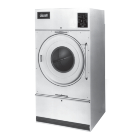
75 lb. laundry dryer
Hide thumbs
Also See for L36URD36E:
- Owner's manual (78 pages) ,
- Maintenance service manual (57 pages) ,
- Owner's manual (74 pages)
Table of Contents
Advertisement
MANUFACTURING COMPANY
INSTALLATION/OPERATION
L36USS36G
L36USD36G
CISSELL MANUFACTURING COMPANY
HEADQUARTERS
831 SOUTH FIRST ST.
P.O. BOX 32270
LOUISVILLE, KY 40232-2270
THIS MANUAL MUST BE GIVEN TO THE EQUIPMENT OWNER.
MAN354
MANUAL
75 Lb. Laundry Dryer
GAS
L36URD36G
L36URS36G
9/98
MODELS
STEAM
L36URS36S
L36URD36S
PHONE: (502) 587-1292
SALES FAX: (502) 585-3625
SERVICE/PARTS FAX: (502) 681-1275
Page 1
ELECTRIC
L36URS36E
L36URD36E
D0561
Advertisement
Table of Contents

Related Manuals for Cissell L36URD36E


Summary of Contents for Cissell L36URD36E
- Page 1 MANUFACTURING COMPANY INSTALLATION/OPERATION 75 Lb. Laundry Dryer L36USS36G L36URD36G L36USD36G L36URS36G CISSELL MANUFACTURING COMPANY HEADQUARTERS 831 SOUTH FIRST ST. P.O. BOX 32270 LOUISVILLE, KY 40232-2270 THIS MANUAL MUST BE GIVEN TO THE EQUIPMENT OWNER. MAN354 9/98 MANUAL MODELS STEAM L36URS36S...
-
Page 2: Important Notices
Do not store or use gasoline or other flammable vapors and liquids in the vicinity of this or any other appliance. WARNING: A clothes dryer produces combustible lint and should be exhausted outside the building. The dryer and the area around the dryer should be kept free of lint. - Page 3 WARNING: Alterations to equipment may not be carried out without consulting with the factory and only by a qualified engineer or technician. Only Cissell parts may be used. WARNING: Remove clothes from dryer as soon as it stops. This keeps wrinkles from setting in and reduces the possibility of spontaneous combustion.
-
Page 4: Cissell Dryer Warranty
Cissell’s factory, transportation prepaid, within the applicable warranty period and found by Cissell to have been defective, and in no event shall Cissell be liable for damages of any kind, whether for any injury to persons or property or for any special or consequential damages. -
Page 5: Table Of Contents
TABLE OF CONTENTS 75 LB. LAUNDRY DRYER PAGE Model Numbers & Company Address ... 1 Important Notices ... 2-3 Dryer Warranty ... 4 Table of Contents ... 5 Warnings, Cautionary Notes and Symbols ... 6-7 Unpacking and General Insulation ... 8 Dryer Outline Dimension (Illustration) ... - Page 6 The following symbols are used in this manual and/or on the machine. between () refer to the numbers on the machine surveys. Symbol SYMBOLS D e s c r i p t i o n NOTE! Hot! Do Not Touch Heib! Nicht Beruhren Haute temperature! Ne pas toucher...
- Page 7 SYMBOLS Symbol Description Part/Measurement rotation in two directions rotation dans les deux sens Drehbewigung in zwei Richtungen movimiento rotativo en los dos sentidos direction of rotation sens de mouvement continu de rotation Drehbewegung in Pfeilrichtung movimiento giratorio o rotatorio en el sentido de la flecha End of Cycle caution attention...
- Page 8 (see adjustable leveling bolts in maintenance section). Check voltage and amperes on rating plate before installing the dryer. The construction of Cissell dryers permits installation side-by-side to save space or to provide a wall arrangement. Position dryer for the least amount of exhaust piping and elbows, and allow free access to the rear of dryer for future servicing of belts, pulleys and motors.
-
Page 9: Dryer Outline Dimension (Illustration)
75 lb. “UR” Dryer Outline Dimensions (Illustration) Page 9... -
Page 10: Dryer Outline Dimension (Illustration)
75 lb. “US” Dryer Outline Dimensions (Illustration) All dimensions given in inches ± 1/4” Page 10... -
Page 11: Specifications
Basket Load Capacity ... 75 lbs. (34.0 kg) dryweight GENERAL SPECIFICATIONS Floor Space ... 75” (191 cm) H x 38” (96 cm) NON-ENERGY SAVER MODELS Basket Size ... 36” (91 cm) diameter x 36” Exhaust Duct ... 8” diameter (20.3 cm) Motor Sizes ... - Page 12 STEAM HEATED MODEL ENERGY SAVER GAS MODEL Specifications Operating Steam Pressure ... 15 PSIG (low pressure) Supply Connection to Solenoid ... 3/4” (1.91 cm) Return Connection ... 1” (2.54 cm) Steam Consumption ... 214, 265 BTU/HR - 6.4 BHP - Drying Time (approximate) ...
-
Page 13: Motor List
DOUBLE MOTOR MODELS Motor No. Voltage MTR203 115/200/230 MTR212 200/230/460 MTR206 110/220 MTR104 240/415 MTR104 220/380 MTR104 220/380 MTR104 200/346 MTR101 MTR209 115/208-230 MTR218 208/230/460 MTR184 240/415 MTR187 220/380 MTR187 220/380 MTR187 200/346 SINGLE MOTOR MODELS Motor No. Voltage MTR246 115/208-230 MTR247 208-230/460... -
Page 14: General Information
ELECTRICAL CONNECTIONS The Cissell Dryer is so designed that when an operator opens the dryer door, the basket and exhaust fan stops. You can expect fast drying from a Cissell Laundry Dryer. Hot, dry air is properly and effectively moved through the basket and exhausted through a lint trap to the atmosphere. -
Page 15: Grounding Instructions
Grounding Instructions (Illustration) Page 15... -
Page 16: Piping Recommendations
PIPING RECOMMENDATIONS STEAM HEATING UNITS Piping Recommendations 1. Trap each dryer individually. Always keep the trap clean and in good working condition. 2. When dryer is on the end of a line of equipment, extend header at least 4 feet beyond dryer. Install globe valve, union, check valve and by-pass trap at end of line. -
Page 17: Gas Piping Installation
GAS PIPING INSTALLATION Gas Piping Check gas rating plate for type of gas to equip the dryer. Check for altitude elevation of the dryer. Check utility for proper installation of gas supply line and gas pressure. NATURAL GAS ONLY Check the gas pressure inlet supply to dryer, 11” W.C. Pressure maximum. - Page 18 Gas Piping Installation (Illustration) The dryer and it’s individual shutoff valve must be disconnected from the gas supply piping system during any pressure testing of that system at test pressures in excess of 1/2 PSIG. The dryer must be isolated from the gas supply piping system by closing it's individual manual shutoff valve during any pressure testing of the gas supply piping system at test pressures equal to or less than 1/2 PSIG.
-
Page 19: Gas Service Installation Instructions
LIQUIFIED PETROLEUM GASES ONLY ! A Gas Pressure Regulator for Liquified Petroleum Gases is not furnished on Cissell Gas Heated Clothes Dryers. This regulator is normally furnished by the installer. In accordance with American Gas Association (AGA) standards, a gas pressure regulator, when installed indoors, must be equipped with a vent limiter or a vent line must be installed from the gas pressure regulator vent to the outdoors. -
Page 20: Gas Pipe Size Chart
TOTAL BTU/HR (for LP Gas correct TOTAL total BTU/HR below by KCAL multiplying by .6) HOUR 15000 60,000 80,000 20000 25200 100,000 30200 120,000 35200 140,000 40300 160,000 45300 180,000 50400 200,000 75600 300,000 100800 400,000 126000 500,000 151200 600,000 176400 700,000 202000... -
Page 21: Steam Piping Installation Instructions
STEAM PIPING INSTALLATION INSTRUCTIONS Steam Piping Installation Instructions 1. Set and anchor dryer in position. Machine should be level to assure proper steam circulation. 2. To prevent condensate draining from headers to dryer, piping should have a minimum 12” above respective header. Do not make steam connection to header with a horizontal or downwardly facing tee or elbow. -
Page 22: Steam Piping Installation
Steam Piping Installation (Illustration) Page 22... -
Page 23: Power Supply
Dryer Installation With Multiple Exhaust For Exhaust Duct less than 14 feet and 2 elbows equivalent and less than 0.3 inches static pressure. Area of section “A-A” must be equal to the sum of dryer exhaust pipes entering multiple exhaust pipe. (See chart below.) MODELS: L28FD30, L28US30, L36FD30, L36UR30, L36CD36, L44FD42 No. -
Page 24: Dryer Installation With Multiple Exhaust
Dryer Installation with Multiple Exhaust DRYER INSTALLATION WITH MULTIPLE EXHAUST For Exhaust Duct more than 14 feet and 2 elbows equivalent and more than 0.3 inches static pressure. (See illustration on next page.) 1. Make-up air from outside building may enter enclosure from top or side walls. -
Page 25: Dryer Installation With Separate Exhaust (Preferred)
Dryer Installation With Separate Exhaust (Preferred) DRYER INSTALLATION WITH SEPARATE EXHAUST (PREFERRED) For ductwork less than 14 feet and 2 elbows equivalent and less than 0.3 inches static pressure: NEVER exhaust the dryer into a chimney. NEVER install wire mesh screen over the exhaust or make-up air area. -
Page 26: Troubleshooting
DRYER AIR FLOW INSTALLATION EXHAUSTING DUCT MAKE-UP AIR OTHER RECOMMENDATIONS TROUBLESHOOTING Exhaust and Venting Nothing is more important than air flow for the proper operation of a clothes dryer. A dryer is a pump which draws make-up air from the out-of-doors, through the heater, through the clothes and then forces the air through the exhaust duct back to the out-of-doors. -
Page 27: Rules For Safe Operation
RULES FOR SAFE OPERATION OF DRYER ENERGY-SAVING TIPS Rules for Safe Operation of Dryer 1. Be sure your dryer is installed properly in accordance with the recommended instructions. 2. CAUTION Be safe—shut main electrical power supply and gas supply off externally before attempting service. -
Page 28: Operating Instructions - Two Timer Models
Operating Instructions - Two Timer Model (Illustration) Page 28... -
Page 29: Operating Instructions - Two Timer Models
Operating Instructions - Two Timer Model OPERATING INSTRUCTIONS - TWO TIMER MODEL TEMPERATURE OPERATING INSTRUCTIONS - TWO TIMER MODEL Step 1. After loading the dryer with water washed clothes, close the loading door. Step 2. Turn the 60 minute drying (heat) timer to the desired time. -
Page 30: Automatic Computerized Drying Control
DESCRIPTION The Automatic Computer Drying Control is used to manage the drying and cooling cycles of one clothes dryer. The operator has the flexibility to select either automatic or timed drying and either automatic or timed cooling. When automatic is selected, the drying cycle will be terminated when the clothes are dry. -
Page 31: Led Display Messages
LED DISPLAY MESSAGES Automatic Computerized Drying Control LED DISPLAY MESSAGES Display “__0” load. “012” timed mode. “012” (Flashing) “-S-” (Flashing) “_PF” (Flashing) “FFF” (Flashing) “-A-” Page 31 Condition Normal display between loads. Dryer is waiting for the next Normal display during drying/ cooling cycle. - Page 32 Automatic Computerized Drying Control OFF/STOP START COOLING TIME DRYING TIME DRYING TEMPERATURE FABRIC SELECTOR OPERATION OF CONTROL PANEL (See drawing on page 33) 1. ON Turn the control on. If dryer is not used for 30 minutes, the power will turn off. Press “on” for power.
- Page 33 DRYING COOLING REPEAT LAST CYCLE NON-REVERSING/ REVERSING LED DISPLAY DRYING COOLING END OF CYCLE OPEN DOOR Automatic Computerized Drying Control OPERATION OF CONTROL PANEL (continued) (See drawing on page 33) 8. DRYING Pressing this button changes the selection of automatic or timed drying, indicated by a light.
- Page 34 Automatic Computerized Drying Control Panel (Illustration) Page 34...
- Page 35 DETAILS OF CONTROL BOARD AND OPTIONS Automatic Computerized Drying Control OPTIONS SWITCH SET #1 Switch #8 F/C #7 SFTY-EN #6 6-Add #5 Repeat S/E #4 2 Deg. #3 5 Deg. #2 10 Deg. #1 20 Deg. Selection of Deg F or Deg C for temperature display.
- Page 36 Automatic Computerized Drying Control DETAILS OF CONTROL BOARD AND OPTIONS REVERSING DWELL COMPUTER RESET 120/230V. SWITCH OPTION SWITCH SET #2 These switches have no function. THERMISTOR CALIBRATION To verify the calibration of the thermistor circuit, proceed as follows: 1. Disconnect the thermistor leads going to the circuit board. 2.
- Page 37 Automatic Computerized Drying Control Board (Illustration) Page 37...
Need help?
Do you have a question about the L36URD36E and is the answer not in the manual?
Questions and answers