Table of Contents
Advertisement
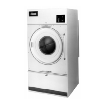
OWNER'S MANUAL
L36USS30G
L36USD30G
CISSELL MANUFACTURING COMPANY
HEADQUARTERS
831 SOUTH FIRST ST.
P.O. BOX 32270
LOUISVILLE, KY 40232-2270
THIS MANUAL MUST BE GIVEN TO THE EQUIPMENT OWNER.
MAN2050 (ECN5662)
Member of:
50 Lb. Laundry Dryer
GAS
L36URD30G
L36URS30G
8/99
MODELS
STEAM
L36URS30S
L36URD30S
PHONE: (502) 587-1292
SALES FAX: (502) 585-3625
SERVICE/PARTS FAX: (502) 681-1275
ELECTRIC
L36URS30E
L36URD30E
Advertisement
Table of Contents
Troubleshooting


Need help?
Do you have a question about the L36USS30G and is the answer not in the manual?
Questions and answers