Table of Contents
Advertisement
Quick Links
Advertisement
Table of Contents

Related Manuals for Datalogic Falcon 5500


Summary of Contents for Datalogic Falcon 5500
- Page 1 Falcon 5500 RFID ® Mobile Hybrid Computer QRG Addendum...
- Page 2 PSC Inc 959 Terry Street Eugene, Oregon 97402 Telephone: (541) 683-5700 Fax: (541) 345-7140 An Unpublished Work - All rights reserved. No part of the contents of this documentation or the procedures described therein may be reproduced or transmitted in any form or by any means without prior written permission of PSC Inc.
-
Page 3: Table Of Contents
Overview ...1 Introduction ...2 Getting Started ...2 Enabling RFID ...2 Reading RFID Tags ...3 Painting ...4 RFID Electrical Considerations ...5 Operating time ...5 Charge time ...5 LEDs/Indicators ...6 RFID Battery Charge LEDs ...6 Discharge indicator ...6 Configuration Settings ...8 Audio ...8 RFID Settings ...9 Report Settings ...9 Power ... - Page 4 Table of Contents NOTES ® Falcon 5500 RFID Mobile Hybrid Computer...
-
Page 5: Overview
Overview This document covers the following topics: Getting Started • Enabling RFID on page 2 • Reading RFID Tags on page 3 Configuration Settings • Audio on page 8 • RFID Settings on page 9 Further Information • About RFID Tags on page 14 •... -
Page 6: Introduction
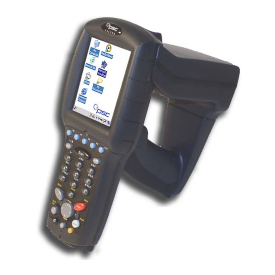
Getting Started Introduction The Falcon 5500 is a Falcon 4420 Windows mounted with a special RFID unit. See the Falcon 4400 Series Quick Reference Guide (QRG) and the Falcon 4400 Series Product Reference Guide (PRG) on the Product CD included with your unit for information not discussed in this RFID Addendum. -
Page 7: Reading Rfid Tags
4. In the Pistol Trigger column, select RFID. 5. Tap For information on other RFID configuration options, see tings on page Reading RFID Tags For tag read demo purposes: Once you have enabled the Falcon to read RFID tags, complete the following steps: 1. -
Page 8: Painting
The RFID Antenna (in the RFID unit) should be positioned to face the tag location. Figure 1. Aiming the Falcon 5500 Configuration Settings on page 8 default settings. For more details about RFID tags, see... -
Page 9: Rfid Electrical Considerations
RFID Electrical Considerations Operating time Under normal operating conditions, the RFID battery will last longer than the Falcon battery. Extended continuous operation may result in the RFID battery discharging before the Falcon battery. When using “paint” mode, the battery will last approximately 3 hours. If the RFID unit fails to operate or produces error messages on the Falcon screen, it could be an indication that the RFID battery is becoming depleted. -
Page 10: Leds/Indicators
RFID Electrical Considerations LEDs/Indicators RFID Battery Charge LEDs These indicators are visible on the back of the RFID pod. The red LED is on when the unit is in a dock and the RFID battery is charging. The green LED is on when the unit is in the dock and the RFID battery has reached full charge. - Page 11 Falcon 5500 Dock Use only the correct battery chargers and docks with the Falcon 5500 RFID. The technology used for this model is incompatible with other PSC Falcon chargers and docks, including the Falcon 4410/4420 color and monochrome models. Go to the PSC website at www.psc.com for information about models and part numbers.
-
Page 12: Configuration Settings
Configuration Settings Configuration Settings Configuration Examples on page 12 different usages. Refer to the Falcon 4400 Series PRG for information about setting other configuration items. Audio 1. Go to Panel icon. 2. Select 3. Choose from the following options: • Volume: lower the audio volume. -
Page 13: Rfid Settings
RFID Settings 1. Go to Panel icon. 2. Select 3. Choose one of the available options. Report Settings In the RFID Decoding Properties, do the following to view or modify Report Set- tings: 1. Under Configure > RFID > Report Settings. Report Frequency RFID tag data is reported to an application. -
Page 14: Power
Configuration Settings Power 1. Under Configure > RFID > Power 2. Enable/disable selecting the checkbox. When dis- abled, a constant level of RF power is output when reading tags. When enabled, the level of RF power starts at a minimum level, and then increases to a maximum level, where it will remain for the duration of the painting operation. -
Page 15: Firmware Version
• New Tag Timeout: painting will automatically stop. This is the maximum amount of time spent waiting for new tags after a tag has been read. If set to Infinite, then painting will stop only when the trigger is released, been read. -
Page 16: Configuration Examples
Configuration Settings Configuration Examples The following examples illustrate ways to optimize RFID settings for specific situations. Reading tagged items from an entire shelf Configuration Item Report Frequency Total Read Timeout Minimum Tag Count New Tag Timeout 1. Press the trigger and move across the items on the shelf. As new tags are found, the Falcon will beep and new data will immedi- ately be sent to an application. - Page 17 Configuration Settings Class 1 Gen 2 Q value Q value sets the number of response slots available for the tags being inventoried (number of slots = 2Q). It is actively managed during an inventory round, but starting with an appropriate Q decreases the time necessary to perform an inventory.
-
Page 18: About Rfid Tags
Read Range The Falcon 5500 RFID has a functional range of two to six feet. Greater read range distances are possible; however, efficiency and predictability of tag data collection will diminish beyond the recommended range. A reduction in func- tional range may result when attempting to read many tags simultaneously (several cases on a pallet) due to tag performance degradation. -
Page 19: Tag Orientation
Single Dipole Antenna Tag Tags that have a single dipole antenna should be vertically positioned for optimal read performance. Factors Affecting Performance • Water or water-based products will inhibit (absorb) the signal. • Metal surfaces near the tags may affect performance. •... -
Page 20: Configuration Parameters
Configuration Parameters Configuration Parameters The following table lists the configuration parameters which have been added to support RFID. For instructions on how to set these parameters, as well as information on all other configuration parameters, consult the Falcon 4400 Series Product Reference Guide (PRG). Code Parameter/ Description Other Controls Label... - Page 21 Code Parameter/ Description Tag Read Adjusts the pitch of the Beep tag read beep frequency. Tone Tag Read Determines the duration Beep of a tag read beep. Duration Specifies the identifier (if any) that is sent by the decoder when parame- ter Send Code ID User ID (Index 0025) is set to 3.
- Page 22 Configuration Parameters Code Parameter/ Description Sets the duration of the Total read operation before it Read stops. This only applies Timeout to reads started by a physical trigger. Sets the duration of time New Tag when no new tags are Read read before a read oper- Timeout...
-
Page 23: Rfid Programming Labels
RFID Programming Labels CLASS 0 ENABLE 0 D 0 0 1 F F 3 E * CLASS 1 ENABLE 0 D 0 1 1 F F 3 E * CLASS 1 GENERATION 2 ENABLE 0 D 0 2 1 F F 3 E * TAG READ BEEP ENABLE 0 D 0 8 1 F F 3 E * READ POWER MODE... - Page 24 RFID Programming Labels TAG READ BEEP TONE 0 D 2 0 0 0 F F 3 E * 0 D 2 0 0 1 F F 3 E * 0 D 2 0 0 2 F F 3 E * 0 D 2 0 0 3 F F 3 E * TAG READ BEEP DURATION 0 D 2 1 0 0 F F 3 E *...
- Page 25 MINIMUM READ POWER 0 D 2 9 0 1 F F 3 E * 0 D 2 9 0 2 F F 3 E * 0 D 2 9 0 3 F F 3 E * 0 D 2 9 0 4 F F 3 E * MAXIMUM READ POWER 0 D 2 A 0 1 F F 3 E * 0 D 2 A 0 2 F F 3 E *...
- Page 26 RFID Programming Labels CLASS 1 GENERATION 2 Q 0 D 3 0 0 0 F F 3 E * 0 D 3 0 0 3 F F 3 E * 0 D 3 0 0 6 F F 3 E * 0 D 3 0 0 9 F F 3 E * 0 D 3 0 1 2 F F 3 E * 0 D 3 0 1 5 F F 3 E *...
- Page 27 TOTAL READ TIMEOUT Infinite 0 D 2 C 0 0 0 0 F F 3 E * 10 seconds 0 D 2 C 1 0 0 0 F F 3 E * 25 seconds 0 D 2 C 2 5 0 0 F F 3 E * 50 seconds 0 D 2 C 5 0 0 0 F F 3 E * 70 seconds...
- Page 28 RFID Programming Labels NEW TAG READ TIMEOUT Infinite 0 D 2 D 0 0 0 0 F F 3 E * 1000 0 D 2 D 1 0 0 0 F F 3 E * 2500 0 D 2 D 2 5 0 0 F F 3 E * 5000 0 D 2 D 5 0 0 0 F F 3 E * 7000...
- Page 29 MINIMUM TAG READ COUNT Inifinite 0 D 2 E 0 0 0 0 F F 3 E * 0 D 2 E 0 0 0 1 F F 3 E * 0 D 2 E 0 0 5 0 F F 3 E * 0 D 2 E 0 1 0 0 F F 3 E * 0 D 2 E 0 1 5 0 F F 3 E * 0 D 2 E 0 2 0 0 F F 3 E *...
- Page 30 RFID Programming Labels READ REPORT FREQUENCY Inifinite 0 D 2 F 0 0 0 0 F F 3 E * 0 D 2 F 0 0 0 1 F F 3 E * 0 D 2 F 0 0 5 0 F F 3 E * 0 D 2 F 0 2 0 0 F F 3 E * 0 D 2 F 0 1 0 0 F F 3 E * 0 D 2 F 0 1 5 0 F F 3 E *...
-
Page 31: Safety Information
5cm (2 inches) from the radio and its integral antenna. CAUTION Radio Type The Falcon 5500 uses a Frequency-Hopping Spread Spectrum (FHSS) radio operating in the 902-928 MHz frequency band. Addendum Safety Information... - Page 32 Safety Information NOTES ® Falcon 5500 RFID Mobile Hybrid Computer...
- Page 33 Safety Information NOTES Addendum...
- Page 34 Safety Information NOTES ® Falcon 5500 RFID Mobile Hybrid Computer...
- Page 36 Asia Pacific PSC Hong Kong Hong Kong Telephone: [852]-2-584-6210 Fax: [852]-2-521-0291 Australia PSC Asia Pacific Pty Ltd. North Ryde, Australia Telephone: [61] 0 (2) 9878 8999 Fax: [61] 0 (2) 9878 8688 France PSC S.A.R.L. LES ULIS Cedex, France Telephone: [33].01.64.86.71.00 Fax: [33].01.64 46.72.44 Germany PSC GmbH...
Need help?
Do you have a question about the Falcon 5500 and is the answer not in the manual?
Questions and answers