Table of Contents
Advertisement
1
INTRODUCTION
1.1
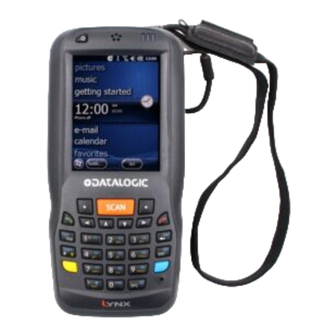
LYNX DESCRIPTION
The Lynx contains the most innovative technical features, providing them to the user
in an ergonomic and elegant form factor. The accelerometer, the vibrator alert and
the 3 LEDs help to do not waste time in the configuration and usage of the product.
Working with the Lynx becomes an easy pleasure.
The great aesthetics does not put the rubustness on a second level.The Lynx has
been deisgned for surviving to industrial environmental, outside and inside the four
walls. The reliability of the product continues with the architecture chosen: an
806MHz processor working with 256 MB RAM and 512 MB of Flash. A Micro SD card
slot supporting SDHC storage cards provides for virtually unlimited storage space.
The Lynx has been equipped with both a 1D laser scanner and 2D bar code imager.
For being ready also to the most demanding applicatinons, an autofocus camera with
flash has been foreseen on the back of the product.
The Lynx provides four wireless technologies in the same form factor, without
antenna protruding: Bluetooth® v2.1 EDR for fast data transfer, 802.11b/g/n with
CCX v4, 802.11i Security, UMTS HSPA+ for real-time communication outside the
four walls and Assisted GPS (A-GPS) with Skyhook's Core Engine hybrid positioning
system for location based applications.
Them micro-USB port facilitates charging with a phone industry standard power
supply or On-the-Go (OTG) communications.
The Lynx integrates the latest Windows Embedded Hend Held 6.5, tailored for mobile
devices.
As all the Datalogic ADC Computers, also this PDA is offering Wavelink Avalanche®
for a fast configuration and deploymant.
Finally, Datalogic's comprehensive service programs protect the Lynx investment.
Advertisement
Table of Contents

Related Manuals for Datalogic Lynx 00N0LD-1N0-MEN0


Summary of Contents for Datalogic Lynx 00N0LD-1N0-MEN0
- Page 1 The Lynx integrates the latest Windows Embedded Hend Held 6.5, tailored for mobile devices. As all the Datalogic ADC Computers, also this PDA is offering Wavelink Avalanche® for a fast configuration and deploymant. Finally, Datalogic’s comprehensive service programs protect the Lynx investment.
-
Page 2: Available Models
For further information regarding Windows Embedded Handheld refer to the website: http://www.microsoft.com/windowsembedded. The currently available models are: 944400000 Lynx 00N0LD-1N0-MEN0 Lynx with Bluetooth v2.0, Wi-Fi 802.11 b/g/n, Decodified Laser (SE955), Windows Mobile 6.5, 27-Key Numeric 944400001 Lynx H2N0LD-1N1-MEN0 Lynx with Bluetooth v2.0, UMTS HSPA+ Voice and Data, Assisted GPS, Wi-Fi... - Page 3 Lynx with Bluetooth v2.0, UMTS HSPA+ Voice and Data, Assisted GPS, Wi-Fi 802.11 b/g/n, Decodified Laser (SE955), Camera, Windows Mobile 6.5, 46-Key QWERTY 944400006 Lynx 00N0WI-1Q1-MEN0 Lynx with Bluetooth v2.0, Wi-Fi 802.11 b/g/n, 2D Imager (4500) Wide Aspect, Camera, Windows Mobile 6.5, 46-Key QWERTY ...
-
Page 4: Package Contents
PACKAGE CONTENTS The Lynx package contains: 1 Lynx PDA 1 Lynx quick start guide 1 rechargeable battery pack (standard for Wi-Fi models, high cap for UMTS models) 1 power supply with regional plugs 1 Lanyard ... - Page 5 Rechargeable battery packs are not initially charged. Therefore the 오류 first operation to perform is to charge them. See paragraph 참조 원본을 찾을 수 없습니다 NOTE...
- Page 6 INSERTING MICROSD CARD Lynx supports microSD memory cards. To access the microSD card slot and insert the card, proceed as follows: Turn off the Lynx. Shift the battery latch to the left and remove the battery pack: Open the card slot and insert the microSD card with the written part downward:...
- Page 7 Shift the card to the right to lock it into the cardholder; close the card slot: First insert the bottom (contacts) and then the upper side of the battery pack into the slot. Press until the battery latch clicks..
-
Page 8: Removing The Microsd Card
1.4.1 Removing the MicroSD Card To remove the microSD card, follow the steps above to access the microSD card cage under the battery, and remove it from microSD slot. Follow proper precautions avoid damaging microprocessors in the Lynx or the microSD card itself. Proper ESD precautions include, but are not limited to, working on an ESD mat and ensuring that the operator is properly grounded. -
Page 9: Installing The Sim Card
INSTALLING THE SIM CARD To correctly insert the SIM Card, proceed as follows: Turn off the Lynx. Shift the battery latch to the left and remove the battery pack: Insert the SIM card with the contacts downwards: First insert the bottom (contacts) and then the upper side of the battery pack into the slot. -
Page 10: Removing The Sim Card
Follow proper ESD precautions to avoid damaging the SIM card. Proper ESD precautions include, but are not limited to, working on an ESD mat and ensuring that the operator is properly grounded. CAUTION Do not force the card. If you feel resistance, remove the card, check the orientation, and reinsert it. - Page 11 ACCESSORIES Cradles 94A150036 Dock, Single Slot, Lynx 94A150037 Charger, 4 Slot Dock, Lynx 94A150038 Dock, Ethernet 4 Slot, Lynx 94A150039 Charger, 4 Slot Battery, Lynx Batteries 94ACC0064 Battery, Standard Capacity, Lynx 94ACC0065 Battery, High Capacity, Lynx Power Supply 94A051975 Power Adapter, 12 to 24v Pwr Plug 2.1mm 94A051976 Adapter, Pwr Jack 2.1mm To Handylink 94ACC1380 Power Supply, Micro USB...
- Page 12 Use only a Datalogic ADC-approved power supply and cables. Use of an alternative power supply will invalidate any approval given to this device and may be dangerous. NOTE...
- Page 13 2. BATTERIES AND MAINTENANCE Rechargeable backup batteries and battery packs are not initially charged. Therefore the initial operation to perform is to charge them. See below. NOTE By default, the battery pack is disconnected at the factory to avoid damage due to excessive draining. Annual replacement of rechargeable battery pack avoids possible risks or abnormalities and ensures maximum performance.
- Page 14 It’s recommended to charge batteries before first use. NOTE Risk of explosion if battery is replaced by an incorrective type. Dispose of used batteries according to the instructions. CAUTION Il y a risque d’explosion si la batterie est remplacée par une batterie de type incorrect.
- Page 15 The Lynx could get warm during charging, this is normal and does not mean a malfunction. NOTE Use only a USB-IF compliant USB port as a charging source. NOTE...
- Page 16 REPLACING THE BATTERY PACK To correctly replace the battery pack, proceed as follows. Turn off the Lynx. Shift the battery latch to the left and remove the battery pack: Install the new battery pack, first insert the bottom (contacts) and then the upper side of the battery pack into the slot.
- Page 17 Use only a Datalogic ADC approved power supply. The use of an alternative power supply will void the product warranty, may cause product damage and may cause heat, explode or ignite.
- Page 18 Do not disassemble or modify (i.e. bend, crush or deform) the battery pack. The battery pack contains safety and protection devices, which, if damaged, may cause the battery pack to generate heat, WARNING explode or ignite. In case of leakage of liquid from the battery, avoid contact with liquid the skin or eyes.
- Page 19 CLEANING THE PDA Periodically clean the Lynx with a slightly dampened cloth. Do not use alcohol, corrosive products or solvents.
-
Page 20: Usb Connection
3. CONNECTIONS USB CONNECTION You can use the standard micro USB cable 94A051968 or the Datalogic Handylink cable 94A051970 to directly connect the Lynx to a host computer to transfer data through the USB interface. Key: Host computer Lynx Standard Micro USB cable... - Page 21 The Single Dock can be connected to the Host by means of the Micro-B USB cord 94A051968. Once the host has been turned on, insert the Lynx PDA into the cradle. Key: Host computer 94A150036 Lynx Single Slot Dock 94A051968 Micro USB Client 94ACC1381 Power Adapter Cable Connection through the cradle complies to 1.1 USB standard.
-
Page 22: Connection To Usb Peripherals
CONNECTION TO USB PERIPHERALS To connect the Lynx to a keyboard or a memory, connect the terminal to the Datalogic 94A051969 cable or to the Datalogic 94A051971 cable (together with a standard A to micro A USB cable). For all these devices maximum current withdrawal must be below 100mA. - Page 23 Connect the Single Slot Dock to the peripheral by means of a Micro-A USB cord, or use a Micro-A to Std-A receptacle USB adapter such as Datalogic 94A051969 (together with a standard USB cable if needed). USB Peripheral (memory) Standard A to Micro A USB Cable...
-
Page 24: Rs232 Connection
RS232 CONNECTION You can use the Datalogic 94A051972 cable to directly connect the Lynx to a host computer to transfer data through the RS232 interface Key: Host computer Lynx 94A051972 Handylink Micro RS232 Client Cable The Single Slot Dock can be connected to the Host by means of a standard null modem cable such as Datalogic 94A051020 CAB-427 for 9-pin connections. -
Page 25: Wlan Connection
WLAN CONNECTION Lynx 802.11 b/g/n radio models can communicate with the host using the on-board radio frequency component and an Access Point connected to the host computer. For models using the 802.11 b/g/n radio, you can find information about the applet for radio configuration: http://www.summitdata.com/SCU.htm. - Page 26 802.11 b/g/n radio module is on by default, in order to avoid wasting energy, you can switch it off using the SCU. NOTE Suspending the terminal powers off the 802.11 b/g/n radio and drops the radio connection. When the terminal resumes, depending on the radio power mode and security protocol selected, it may take up to 30 seconds for the 802.11 b/g/n radio driver to re-associate the radio NOTE...
- Page 27 WPAN CONNECTIONS Lynx Bluetooth®, models can communicate with a Bluetooth®, device, such as a printer, within a range of 10 m, using the on-board Bluetooth®, module. Key: A) Lynx B) Bluetooth®, printer In order to extend battery life, the Bluetooth®, module is off by default.
- Page 28 NOTE...
- Page 29 WWAN CONNECTION Lynx GSM models enhance your connectivity solutions giving you an opening to an international wireless infrastructure that is the global standard. GSM (Global System for Mobile communications) is a digital mobile phone system based on TDMA; it utilizes the 850, 900, 1800 and 1900 MHz bands. ...
- Page 30 The GSM voice capability of this PDA has to be addressed to occasional use, in well covered areas. If the coverage is poor, the voice quality can be highly affected. NOTE...
- Page 31 Calls can be made or received using the Lynx as a phone handset, by the Lynx headset or by a Bluetooth® headset. NOTE During a call, you can set the speaker volume by pressing the arrow navigation keys. NOTE In case of heavy usage the Lynx could get warm, this is normal and does not mean a malfunction.
-
Page 32: Wireless And Radio Frequencies Warnings
However, certain electronic equipment may not be shielded against the RF signals generated by Lynx. WARNING Datalogic recommends persons with pacemakers or other medical devices to follow the same recommendations provided by Health Industry Manufacturers Associations for mobile phones. Persons with pacemakers: WARNING ... - Page 33 RF signals may affect improperly installed or inadequately shielded electronic systems in motor vehicles. Check with the manufacturer or its representative regarding your vehicle. You should also consult the manufacturer of any equipment that has been added to your vehicle. WARNING An air bag inflates with great force.
-
Page 34: Use And Functioning
4. USE AND FUNCTIONING The use of the Lynx depends on the application software loaded. However there are several parameters that can be set and utilities that can be used to perform some basic functions such as data capture, communications, file management, etc STARTUP The Lynx turns on when the battery pack or the external supply is inserted and the ON/OFF Power button is pressed. -
Page 35: Using The Stylus
To recalibrate the touch screen use the Stylus Applet (see par. 1.6.7). Use only original Datalogic styluses supplied with the product itself. In harsh applications, use of screen protectors should be taken into consideration, in order to extend the touch screen operating life. -
Page 36: Windows Embedded Handheld Welcome Wizard
WINDOWS EMBEDDED HANDHELD WELCOME WIZARD In Windows Embedded Handheld, at the very first Lynx startup, following a clean boot or following a registry restore to default values, the PDA startup (see par. 1.1) is preceded by the Welcome Wizard. Welcome Wizard Screen The Welcome Wizard allows the user to calibrate the touch screen (see par. -
Page 37: Data Capture
DATA CAPTURE To capture data first of all tap Start > Settings > System > Decoding: To configure and enable data capture parameters refer to par. 1.6.1. -
Page 38: Laser Data Capture
1.3.1 Laser Data Capture To scan barcodes, point the Lynx laser model onto the code from a distance within the reading range while pressing the SCAN key. The lighted band emitted by the laser must completely cross the barcode as shown in the figure below. - Page 39 Remove the protective film cover over the Laser Output Window before use. NOTE...
-
Page 40: Imager Data Capture
1.3.2 Imager Data Capture The Lynx Imager captures a picture of the entire bar code. The omni-directional scanning does not require that the operator orient the bar code to align with the scan pattern. To read a 1D or 2D code, simply point the Lynx Imager model onto the code and press the SCAN Key. - Page 41 Linear barcode 2D Matrix symbol Ì BX3 ÉÎ Relative Size and Location of Aiming System Pattern The field of view changes its size as you move the reader closer or farther away from the code. The field of view indicated by the aiming system pattern will be smaller when the Lynx Imager is closer to the code and larger when it is farther from the code.
- Page 42 DESCRIPTION OF THE KEYS The Lynx comes with two different keyboards, an alphanumeric keyboard (qwerty), having 46 keys, and a numeric keyboard, having a total of 27 keys. 1.4.1 Alphanumeric Keyboard...
- Page 43 Numeric Keyboard...
-
Page 44: Main Keys Function
Main Keys Function FUNCTION It starts barcode data capture. They let you move forwards, backwards, upwards or downwards within text fields, scroll through a Menu list or browse among folder files. Yellow modifier (toggle key): when pressed before a standard key, it enables the character or function printed in yellow above the key. -
Page 45: Resetting The Lynx
1.4.2 Resetting the Lynx There are several reset methods for the Lynx. A warm boot terminates an unresponsive application and clears the working RAM, but preserves the file system. Registry is restored from persistent memory if available or returned to factory default. A cold boot forces all applications to close reinitializing completely the system. - Page 46 Clean Boot To perform a clean boot, do the following steps: Perform a Cold Boot (see Cold Boot) Press and hold down the 0 and hang up keys simultaneously and then press the on-off key: A dialog box will appear asking for confirmation. Press the Enter Key. Warm Boot Cold Boot Clean Boot...
-
Page 47: Status Indicators
STATUS INDICATORS 1.5.1 LED Status The Lynx provides three different LEDs signaling the PDA status. STATUS Scanning LED is ON from the time the Good Read user hits the scan button (Trigger) until the bar code is decoded (laser models) (right side) Time-out (imager models). - Page 48 1.5.2 Taskbar The Taskbar provides information about the time, the battery level, the keyboard function, and the decoding status. Windows Embedded Handheld Taskbar ICONS DESCRIPTION Zooms the screen. Opens the Wireless Manager (see par. 1.6.6). Displays the system battery status. Allows to set the volume of screen taps.
-
Page 49: Control Panel
CONTROL PANEL From the Start menu, tap Settings. The Control Panel is split into three sections: Personal, System, Connections. Control panel applets are displayed as icons; each icon corresponds to one applet: Windows Embedded Handheld Control Panel... -
Page 50: Data Capture Configuration
1.6.1 Data Capture Configuration You can configure the Lynx’s decoding options by tapping Start -> Settings -> System -> Decoding: There are two sections in the Decoding control panel, each containing additional pages. There are seven General Configuration pages and multiple Barcode symbology pages. - Page 51 Audio From the Decoding menu, tap Configure > General > Audio. Use it to set volume, tone, duration, and number of various types of beeps. Good Read From the Decoding Properties page, tap Configure > General > Good Read. Use it to enable Good Read indications, the use of Green Spot and a to set the decoding timeout for decoding labels.
- Page 52 Formatting From the Decoding Properties page, tap Configure > General > Formatting. Use it to configure prefix, suffix and data separator character strings. General Options From the Decoding menu, tap Configure > General > General Options. Select from Label Programming Enable, Symbology IDs and Group Separator Replacement.
- Page 53 Decoding Options From the Decoding Properties page, tap Configure > General > Decoding Options. Use it to configure the User ID for symbologies, Redundancy and Aggressive Decoding (if supported by the decoding module). Select a symbology to view or change the available properties settings.
- Page 54 Spot Beam From the Decoding Properties page, tap Configure > General > Spot Beam. It allows enabling and configuration of Spot Beam and triggering modes. It is only available on devices equipped with laser and advanced long range laser decoding modules that support the Spot Beam Feature.
-
Page 55: Imager Options
Imager Options From the Decoding Properties page, tap Configure > General > Imager Options. It configures illumination, target beam and Pick List mode, and triggering modes. It is only available on devices equipped with 2D decoding engines. - Page 56 Devices From the Decoding Properties page, tap Configure > General > Devices. Use it to enable or disable the keyboard wedge for Barcode scanner.
- Page 57 1D Barcode Symbology Pages Use the drop-down menus from Configure > 1D Barcode, or tap the left and right arrow keys to navigate the different pages of the barcode symbology pages. Each barcode symbology opens to its own page, as shown in the figure below. Refer to the sample symbology control panels for examples of the types of fields and options you can modify.
- Page 58 Decoding Settings Select from the Decoding Properties Settings menu to restore previous configurations and/or other available default settings. Choose from: Factory Defaults Minimum Settings Maximum Settings Save (New Settings) Revert to Saved Settings The settings are saved when you tap OK. The settings are saved when you tap ‘Yes’.
- Page 59 1.6.2 Buttons From the Start menu, tap Settings > Personal > Buttons. On the Program Buttons tab, customize the program hardware buttons to launch your most used applications. Under ‘Select a button’, tap the button you want to assign a program to, and then select a program from ‘Assign a program’.
- Page 60 1.6.3 DL Buttons In Windows Embedded Handheld devices, <F1>-<F10> buttons (excluding F5) are assigned by Windows to default applications. To customize one of these buttons and assign it to a different application, you first need to disable it. Tap Start > Settings > System > DL Buttons to display the DL Buttons window: Select the button you want to disable.
- Page 61 A dialogue box appears, asking for confirmation. Click ‘Yes’: To add the button back, click ‘New’ and write the name of the button on the box that appears:...
- Page 62 To assign a new application to the button, select the function and then click ‘OK’: To restore the old settings , do a clean boot.
- Page 63 1.6.4 Triggers Triggers are special customizable buttons that are mapped by default by DL Mobile. Also, they can be set as wakeup buttons: TRIGGER APPLICATION Scan Bar Code Bar Code Pistol Trigger...
-
Page 64: Application Switcher
1.6.5 Application Switcher The application switcher provides the same functionality as the standard Windows® Alt+Tab function. This allows the user to switch between the various open applications. The application switcher is activated via an assigned shortcut key specified in the “DL Buttons”... - Page 65 1.6.6 Wireless Communications The Wireless Manager application is a sort of 'Control Panel' for wireless connections. From here it's possible to turn on or off bluetooth® and radio modules. Open the Wireless Manager by tapping Start > Settings > Connections > Wireless Manager, or by tapping the connectivity icon on the taskbar (see par.
- Page 66 Summit Client Utility (SCU) Wireless networking has a customized control, Summit Client Utility (SCU), specific to the radio. From the Start menu, tap: Summit > SCU: The SCU will open to the “Main” tab: Summit Client Utility...
- Page 67 To create a new profile, tap the "Profile" tab: Information about the wireless network can be entered directly in the profile tab or by pressing “Scan” when the desired network ESSID is in range. At the "Scan" screen, select the desired SSID:...
- Page 68 Click the "Configure" button Follow the on-screen instructions to setup security parameters for your network. For more detailed settings specific to your installation please contact your wireless network administrator. When finished, click “Commit” to save your settings. Return to the “Main” tab, if you have not previously selected “Commit” you will be prompted to save your changes.
- Page 69 At the “Main” tab select the profile you just created. If you used the “scan” button the desired profile will have the same name as the ESSID. Use the “Status” tab to check connectivity to the network. More detailed information about the applet for radio configuration can be found at http://www.summitdata.com/SCU.htm.
-
Page 70: Stylus Calibration
1.6.7 Stylus Calibration You might need to recalibrate the touch screen (i.e. when you attempt to select one item with the stylus, another item is erroneously selected). To recalibrate the touch screen, complete the following steps: Select Start > Settings > System > Screen to open the Screen Settings dialog as shown in the figure below: Tap Align Screen to open the Calibration screen shown in the figure below. - Page 71 Startup Stylus Calibration When starting the terminal, a Welcome Wizard (with Stylus Calibration) comes up if valid calibration settings are not available. This happens in the following circumstances: At the first startup of the terminal. After any cold boot if the user skipped stylus calibration earlier. After a Clean Boot.
-
Page 72: Audio Settings
1.6.8 Audio Settings There are two applets that control volume: Audio and Volume & Sounds. Audio From the Start Menu, tap Settings > System > Audio: The audio control panel can be used to independently set the playback or recording volume for different types of audio inputs and outputs, such as a headset, powered mobile dock, or the internal speakers and microphone. - Page 73 Sounds & Notifications From the Start Menu, tap Settings > Sounds and Notifications: The Volume & Sounds applet configures audio features of all speakers and headphones: Sounds Tab Notifications Tab...
- Page 74 To set the Bluetooth® headset volume, you can also tap: Start > Settings > System > Bluetooth Manager > Connections and select the headset. The following window will appear:...
-
Page 75: Windows Connections
WINDOWS CONNECTIONS To connect the Lynx to another device (i.e. Host PC) from Windows, several programs are available. These programs require specific electrical connections in order to function properly. 1.7.1 Windows Mobile® Device Center The desktop application Windows Mobile® Device Center gives you the ability to synchronize information between a desktop computer and your Lynx. - Page 76 Visit the following Microsoft Web site for the latest in updates and technical information: http://www.microsoft.com/windowsphone/en- NOTE us/howto/wp6/sync/prepare-to-sync-windows-phone-6-5-with-my- computer.aspx When a microSD card is inserted, Lynx allows a mass storage data connection to a host PC. This functionality can be enabled through the Control Panel.
- Page 77 1.7.2 Bluetooth®, Manager Device Setup The Bluetooth® Manager icon will only be visible if Bluetooth® hardware has been installed on the unit. NOTE Using the Lynx to connect to another device To create a Bluetooth® pairing between your device and another device that has Bluetooth®...
- Page 78 Once searching is complete, Bluetooth® device Profiles will be displayed in the Discovery tab. You can set up a connection to a device in the list by selecting the device and then tapping the 'Connect' button: To create a pairing: Select a service: Configure any encryption, authentication, or virtual port options required by the service selected.
- Page 79 Icon Service Dialup Networking Printer Object Push (OPP) Object Exchange (OBEX) ActiveSync Human Interface Device (HID) - Keyboard Serial Personal Area Network (PAN) Modem Headset Handsfree Virtual Port allows you to specify the incoming port, which is used to communicate serially with an incoming device just as if it were a physical COM port.
- Page 80 You can also select Encrypt or Authenticate from the Bluetooth® control panel to apply or modify those settings. To require Authentication, check the checkbox, then tap OK. If required, the Authentication Request dialog will then open, requesting that you enter a PIN. Use the Input Panel or the keyboard to type the PIN. Tap OK to complete.
- Page 81 The dialog will also appear when an Authentication request is received from another device. Once you have set up a Pairing, you can view the settings by double-tapping its name from the Connections tab. Tap the arrow to change the Virtual Port, or Delete to remove the device pairing.
- Page 82 Using your device to connect to the Lynx Before turning on Bluetooth®, ensure that the two devices are within close range and that both Bluetooth-enabled devices are discoverable. Tap Start > Settings > System > Bluetooth Manager to open the Bluetooth® control panel.
- Page 83 Select or clear the “Enable Bluetooth Radio” check box. If you’re going to be attaching a serial device (i.e. a scanner) to the Lynx, use the Port control to select a virtual COM port to use for the connection. Tap ‘Find Me’ if you want to make the Lynx visible to other Bluetooth® devices for 60 seconds, allowing them to set up a connection.
- Page 84 By default, Bluetooth® is turned off. If you turn it on, and then turn off your device, Bluetooth® also turns off. When you turn on your device again, Bluetooth® turns on automatically. NOTE...
- Page 85 1.7.3 Windows Mobile Phone For information on Windows Mobile Phone use and functioning, refer to the Windows Mobile web site: http://www.microsoft.com/windowsmobile.
-
Page 86: Configuring Xps
SKYHOOK° XPS SETTINGS 1.8.1 XPS - Virtual GPS for Windows Mobile Skyhook synthesizes data from Skyhook's Wi-Fi Positioning System (WPS), GPS satellites and cell towers with advanced hybrid positioning algorithms combining as much as possible to build a composite position and to provide the best possible location available in any environment. - Page 87 Storage – tab Temporary folder: Select the folder on your device or storage card where the XPS application will store data files. Temporary folder max size: This controls the amount data storage allocated to the XPS Settings application (default setting is 4096kb). Port –...
-
Page 88: Uninstalling Xps
Service – tab Activate / Deactivate: Toggles the XPS service On and Off. About – tab About: View the XPS version and copyright information. 1.8.3 Uninstalling XPS To remove XPS from your Windows Mobile device: Open the Settings panel Open the System panel Tap ‘Remove Programs’... -
Page 89: Faq And Troubleshooting
1.8.4 FAQ and Troubleshooting Can I install to a storage card? Yes – however, as with most mobile apps installing to the device is recommended. What does registering XPS as my default GPS do? Registering XPS simply sets the Windows Mobile OS to use XPS whenever an application asks for positioning. -
Page 90: Datalogic Firmware Utility
Refer to the Product CD included with your device for more information. If Wavelink Avalanche™ is not available or you have only a few Datalogic ADC devices to update, use the Datalogic Firmware Utility (DFU), described below, to install or update the firmware using an ActiveSync connection. -
Page 91: Installing Dfu On The Host Pc
PC. NOTE To install the Datalogic Firmware Utility, complete the following steps on the PC: Insert the CD ROM shipped with your device into the PC and click on the link to install Datalogic Firmware Utility. -
Page 92: Updating The Firmware
Updating the Firmware After copying the firmware image to the host PC (see par. 4.10.1) and installing DFU (see par. 1.9.2), you can upgrade the firmware on your Datalogic device. The following steps require that you have already established an ActiveSync or Windows Mobile®... -
Page 93: Datalogic Configuration Utility
After altering the device’s configuration, the new configuration can be sent to the terminal by clicking on the Send to Device icon. Reference the Wavelink Avalanche™ documentation on your Datalogic CD for a description of indirect mode for DCU, which will allow you to update the configuration... - Page 94 1.11 SUSPEND MANAGEMENT Suspend Management allows the user to keep device features powered while the device is off. The features managed by this feature are: Cellular Data/Voice and GPS. The WiFi driver has been measured to consume about 50 µA when left powered.
- Page 95 The user is given five seconds to respond. If the user selects "Yes", then the device and all features are powered off. If the user selects "No", or does not respond within five seconds, the device will power off, but leave features as they were. The term "device off"...
-
Page 96: Datalogic Desktop Utility
• Create quick access hot keys and configure trigger actions. To open the DDU for the first time, tap Start > Settings > System > Datalogic Desktop Utility or Start > Device tools > Datalogic Desktop Utility. You can also get into DDU by pressing Alt-6. - Page 97 1.12.1 Administrative Options (Admin tab) When you open the DDU control panel, the “Admin” tab appears. COMMAND DESCRIPTION Enable Datalogic Desktop Select/tap this checkbox to activate the DDU functions such as Windows Access Restrictions and Application Selector. Enter Password Enter a password in the text box. This allows the user to specify a password when this utility is launched.
-
Page 98: Setting A Password
You must select/tap “Set Password” prior to exiting DDU in order to store and activate your new password. It is not necessary to select “Enable Datalogic Desktop”. NOTE If you select/tap “Set Defaults” it will remove all custom settings and restore all the factory default settings, except a previously set password. -
Page 99: Removing A Password
Enter blanks in both “Password” fields. Select/tap “Set Password”. Password Request Dialog Box Once the password is set, the next time you open the “Datalogic Desktop Utility”, the DDU Password dialog box opens. This dialog box will only open if a password was defined. - Page 100 1.12.2 WebAppLock Options (WebAppLoc tab) Tap the "WebAppLocK” tab to access the WebAppLock Configuration options. Error Page Redirection Use the Error Redirection option to provide customized recovery from common errors. When an error occurs, the browser can redirect access to a specified error page with instructions on how to recover from the problem.
- Page 101 Other options Full Screen Set the web browser in full screen mode. Status Icon Enable or disable the status icons view (see par. 1.12.3). Trap Keys When checked, all key presses will be trapped by WebAppLock to prevent the user from accessing other parts of the system. DL Buttons keys will not work in WebAppLock when this box is checked.
- Page 102 1.12.3 Status Icons Options (Status Tab) Tap the “Status” tab to access the Status Icons option. You can configure the view of some status icons that are used in “WebAppLock” and in “Application Selector” to display the status of: wi-fi radio, battery and GSM. Status Icons Options Set Status Icon Defaults Restores the status icons’...
-
Page 103: Windows Controls
Windows Controls 1.12.4 Select/tap the “Win” (Windows Controls) tab to access the Windows Controls option. Use Windows controls to allow or restrict access to Windows system functions. You can disable normal Windows functions such as the taskbar, leaving nothing but a blank workspace. - Page 104 WINDOWS CONTROLS Taskbar Enabled Select/tap “Taskbar Enabled” to specify whether the taskbar is accessible. This option is only available when the “Show Taskbar” is checked. AutoSIP Enabled Enables the AutoSIP Windows feature. This control only take effects in WebAppLock. Scroll Bars Enabled When checked, displays horizontal and vertical scroll bars to help view large web pages which do not fit the screen.
- Page 105 1.12.5 AppSelector Options (AppSelect tab) Tap the Application Selector (“AppSelect” Tab) to edit, add, or delete applications for the application selector. Application Selector Options Enable Application Selector Select/tap “Enable Application Selector” enable/disable the application selector. When this is enabled, the Application Selector replaces the desktop allows only...
- Page 106 Add Applications The “Add Application” dialog opens when you tap either “New” or “Edit”. From the “Add Application” dialog the administrator can configure and/or add/change an a new application entry in the list. Applications with the “Run Application at Startup” option enabled will start automatically when the Application Selector starts up.
- Page 107 COMMAND DESCRIPTION Select/tap to browse for the desired icon file. The Browse results of this search are placed in the “Icon File” textbox. Select/tap this box to force this application to auto start when the Application Selector starts up. Applications Run Application at Startup will be started in the order listed in the authorized application list.
- Page 108 1.13 APPSELECTOR (APPLICATION SELECTOR) The Application Selector is an application that allows a device to run in kiosk mode. The administrator can choose for the user to have access to the desktop or not. The Application Selector can replace the desktop and limit the user to the specified list of applications.
- Page 109 1.14 WEBAPPLOCK (LOCKED WEB BROWSER) WebAppLock is a web browser that creates a restricted internet usage environment. It prevents the user from exiting the web application/ website set by the administrator. Zoom In and Zoom Out will only affect screen text and not bitmaps. NOTE If the taskbar has been disabled, the Settings menu is not displayed.
- Page 110 For firmware versions 1.60 and greater, the following command line arguments are supported: /E optional parameter which allows for Exit without entering a password @URL optional parameter which specifies a URL to use as a home page. /C optional parameter which disables the ctrl keys (including the one to exit). /W optional parameter which allows for a performance boost.
- Page 111 </head> tag set. Also, the head tag set must be complete within the first 15K of the web page. The Datalogic WebAppLock defines some special meta-tags that allows the web application to interact with the device: In particular, the special meta-tags allow to:...
- Page 112 CGI Error Meta-tag DL_CGIError – Overrides DDU error page redirection and replaces it with a reference to a CGI script which is passed the error number as an argument. Content – A CGI URL with variable name argument in place. The name of both the CGI function and the error number variable is completely configurable by the user.
- Page 113 GetSerialNumber Meta-tag DL_GetSerialNumber – Obtains the device serial number and sends it as an argument to a customer’s javascript function. Content – name of function to pass serial number to. Example: <meta http-equiv="DL_GetSerialNumber" content="Javascript:CustomerFunction"> When this page is loaded the specified javascript function with the device serial number as the only argument (such as CustomerFunction(‘D10P00031’).
- Page 114 Decoding meta-tags: Each decoding meta-tag has a possible content of “Enable” or “Disable”. The settings are valid for the entire page (enable/disable each symbology). DL_Code_39 DL_Code_128 DL_Code_I25 DL_Code_S25 DL_Code_M25 DL_Code_CODABAR DL_Code_93 DL_Code_UPCA DL_Code_UPCE DL_Code_EAN13 DL_Code_EAN8 DL_Code_MSI DL_Code_MSR DL_Code_GS1_14 DL_Code_GS1_LIMIT DL_Code_GS1_EXP DL_Code_16K DL_Code_49 DL_Code_PDF417...
- Page 115 Key press Metatags The key press meta-tags can be used to call JavaScript functions. They have the name structure: “DL_Key_xxx” where xxx is the VKey code. Example: <meta http-equiv="DL_Key_13" content="Javascript:CheckEnter();"> If one of this tag is present, the pressure of this key is handled at level of page, independently from the currently focused item.
-
Page 116: Installing Cab Files
1.15 AUTOSTART The AutoStart program provides three functions: Allows you to create a list of applications (with optional command line arguments) to run automatically prior to loading CAB files. Automatically reinstalls specified CAB files when the Lynx 10 is cold booted. Allows you to create a list of applications (with optional command line arguments) to run automatically after loading CAB files. -
Page 117: How Autostart Uses Wceload
1.15.2 How AutoStart Uses Wceload If you intend to create highly interactive installers, you should either install the CABs manually or review the section on “Interactive CAB Install” in this chapter.. NOTE In certain environments, CAB files will be deleted after execution. To prevent the CAB file from being deleted, write protect the file before copying the file onto the device. - Page 118 1.15.3 Interactive CAB Install If the CAB installer requires user interaction that must be performed during the AutoStart CAB installation process, you can specify a special file name to disable the silent mode installation. If this mode is specified, the CAB file will be installed with without any command line Wceload...
- Page 119 The following table breaks down the sample Autostart.ini line: Autostart option(s) Full path to executable Command line arguments \windows\pword.exe \file.doc Spaces must be placed between each component of the line in the Autostart.ini. If the executable path is in a folder that contains spaces in the name, quotes are required to distinguish what the actual executable name is.
- Page 120 AutoStart Options The table below shows options you can use when writing a line in the Autostart.ini file. Description Character Comments This may only be used as the first character of the line. If the Comment: This line will not be ‘#’...
- Page 121 Combining Options Autostart options can be combined together as shown in the following sample: ?- \Windows\Pword.exe This line would: Request confirmation before executing the line. The next line would not be processed before the confirmation is answered. Run the next line without waiting on the current line to complete execution. Query Option The query option is intended for use when debugging the autostart.ini.
- Page 122 The fields may be broken up into multiple lines (as shown in the example) due to limited space in the dialog. NOTE AutoStart Query Options Parentheses are used to surround the given field and make it very clear what the value of the field is.
- Page 123 Autostart.ini Samples The next table is a collection of sample Autostart.ini lines: Line Description This will confirm execution ? \windows\wceload.exe “\My \Windows\wceload.exe with specified argument Documents\Sample.cab” “\My Documents\Sample.cab” (invalid) This will execute \Program with the \Program Files\App.exe argument Files\App.exe. (invalid) This will execute \Program with the \Program Files\App.exe /run argument Files\App.exe /run.
-
Page 124: Technical Features
5. TECHNICAL FEATURES TECHNICAL DATA PHYSICAL CHARACTERISTICS DIMENSIONS (LXWXH) 157 x 81x 42 mm (6.18 x 3.18 x 1.65 in) WEIGHT 415 to 440 g (14.6 to 15.5 oz) depending on model (incl. (DEPENDING ON MODEL) battery) Loudspeaker AUDIO Headset LEDS Six LEDs Decoding Status/ Keyboard Status/ Charging Status Reflective TFT daylight readable color display, allowing both... - Page 125 SYSTEM Microsoft Windows Mobile 6.5 with Office Mobile 2010: OPERATING SYSTEM Outlook, Word Mobile, Excel Mobile, PowerPoint Mobile, One Note Mobile and Internet Explorer Mobile 6.0 MICROPROCESSOR XScale™ PXA310 @ 624 MHz SYSTEM RAM MEMORY 256 MB 256 MB (including backup directory for user data & program SYSTEM FLASH MEMORY permanent storage) Removable battery pack with rechargeable Li-ion batteries;...
- Page 126 READING OPTIONS LASER CHARACTERISTICS SCANNING RATE 104 ± 12 scan/sec MINIMUM RESOLUTION 0.10 mm / 4 mils DEPTH OF FIELD 5 to 64 cm (2 to 25 in), depending on bar code density SKEW ANGLE ± 50° PITCH ANGLE ± 65° AIMING LASER VLD, wavelength 630~680 nm GS1 Databar, EAN/UPC, Code 39, 2/5 Codes, Plessey,...
-
Page 127: Reading Diagrams
READING DIAGRAMS Lynx 1D Typical Reading Diagram - Reading Zones (10° skew angle) 1,00 mm (40 mils) 0,35 mm 1,4 mm 0,50 mm (14 mils) (55 mils) (20 mils) 0,25 mm (10 mils) 0,19 mm (7,5 mils) 0,13 mm (5 mils) 1000 1100 1200... - Page 128 LYNX SE4500-DL Typical Reading Diagram - Reading Zones (10° skew angle) 13 mil 20 mil UPC-A Code 39 10 mil 15 mil 6.67 mil PDF417 PDF417 PDF417 5.0 mil 7.5 mil PDF417 Code 39 5.0 mil Code 39...
-
Page 129: Test Codes
6. TEST CODES High Density Codes 0.25 mm (10 mils) !17162H! Code 39 17162 Ë"8NduÌ 2/5 Interleaved 0123456784 ÌtestwÎ Code 128 test x(0B2DE5*KKKKLM( EAN 13 (6450*TRMN( EAN 8 Medium Density Codes 0.38 mm (15 mils) !17162H! Code 39 17162... - Page 130 Ë"8NduÌ Interleaved 2/5 0123456784 ÌtestwÎ Code 128 test 100% x(0B2DE5*KKKKLM( EAN 13 100% (6450*TRMN( EAN 8 Low Density Codes 0.50 mm (20 mils) !17162H! Code 39 17162 Ë"8NduÌ Interleaved 2/5 0123456784...
- Page 131 ÌtestwÎ Code 128 test 120% x(0B2DE5*KKKKLM( EAN 13 120% (6450*TRMN( EAN 8...
- Page 132 2D Codes Datamatrix ECC200 Example Inverse Datamatrix ECC200 Example...
- Page 133 DECODING PARAMETERS This section contains information about programmable settings for the Lynx™. Use the Lynx™ Management Utility (FMU), the Scanner Control Panel applet, the Imaging Control Panel applets to program the Lynx™. It provides the following information: Code Parameter is the “human” name for the programming option. ...
-
Page 134: Programming Codes Without Parameters
PROGRAMMING CODES WITHOUT PARAMETERS The following table describes the functions of special bar codes that take no parameters: Code I.D. # Function Parameter Defaults Turns every On/Off parameter off and sets all minimum and FF39 Minimum Maximum Label Lengths to the lowest values. Turns every On/Off parameter on and sets all minimum and Maximum Label Lengths to the highest values. -
Page 135: Bar Code Parameters
BAR CODE PARAMETERS The following table lists the standard customer programmable settings for the Lynx™: Codabar Defaults Scanner Type Code Accept. Description I.D.# Parameter Input Enter 1 for On and 0 for Off Enables/disables the 0300 On or Off √ √... - Page 136 Defaults Scanner Type Code Accept. Description I.D.# Parameter Input This feature specifies the maximum allowable length of a Codabar label. Maximum The length includes check 0321 01 - 50 √ √ √ Label and data characters. Maximum Label Length Length should be greater than or equal to Minimum Label Length.
- Page 137 Code 39 Defaults Scanner Type Code Accept. Description I.D.# Parameter Input Enter 1 for On and 0 for Off Enables/disables the Code 0100 On or Off √ √ √ Enable 39 symbology. Enables more aggressive Enable decoding algorithms to be 0101 On or Off √...
- Page 138 Pharmacode 39 (Code 32) Defaults Scanner Type Code Accept. Description I.D.# Parameter Input Enter 1 for On and 0 for Off Enables/ disables the Pharmacode 39 (Code 32) 0110 On or Off √ √ √ Enable symbology. Instructs the terminal to Send include the checksum in 0112...
- Page 139 Trioptic Defaults Scanner Type Code Accept. Description I.D.# Parameter Input Enter 1 for On and 0 for Off Enables/disables the 0108 On or Off √ √ Enable Trioptic symbology Enables more aggressive Enable decoding algorithms to be 0109 On or Off √...
- Page 140 Code 93 Defaults Scanner Type Code Accept. Description I.D.# Parameter Input Enter 1 for On and 0 for Off Enables/disables the Code 0400 On or Off √ √ √ Enable 93 symbology. Enables more aggressive Enable decoding algorithms to be 0401 On or Off √...
-
Page 141: Code 128
Code 128 Defaults Scanner Type Code Accept. Description I.D.# Parameter Input Enter 1 for On and 0 for Off Enables/disables the Code 0408 On or Off √ √ √ Enable 128 symbology. Enables more aggressive Enable decoding algorithms to be 0409 On or Off √... - Page 142 Defaults Scanner Type Code Accept. Description I.D.# Parameter Input Specifies the symbology identifier (if any) that is sent when parameter Send single Code ID (Index 0025) is 0427 ASCII ‘K’ ‘K’ ‘K’ √ √ √ User ID set to 3. ASCII code zero character (null) is used to indicate that an identifier is not to...
- Page 143 European Article Numbering-13 (EAN-13) Defaults Scanner Type Code Accept. Description I.D.# Parameter Input Enter 1 for On and 0 for Off Enables/disables the EAN- 0510 On or Off √ √ √ Enable 13 symbology. Enables more aggressive Enable decoding algorithms to be 0511 On or Off √...
- Page 144 Defaults Scanner Type Code Accept. Description I.D.# Parameter Input Specifies the symbology identifier (if any) that is sent by the decoder when single parameter Send Code ID (Index 0025) is set to 3. 0525 ASCII ‘M’ ‘M’ ‘M’ √ √ √...
- Page 145 European Article Numbering-8 (EAN-8) Defaults Scanner Type Code Accept. Description I.D.# Parameter Input Enter 1 for On and 0 for Off Enables/disables the EAN- 0518 On or Off √ √ √ Enable 8 symbology. Enables more aggressive Enable decoding algorithms to be Aggressive 0519 On or Off...
- Page 146 Universal Product Code-A (UPC-A) Defaults Scanner Type Code Accept. Description I.D.# Parameter Input Enter 1 for On and 0 for Off Enables/disables the UPC- 0500 On or Off √ √ √ Enable A symbology. Enables more aggressive Enable decoding algorithms to be Aggressive 0501 On or Off...
- Page 147 Universal Product Code-E (UPC-E) Defaults Scanner Type Code Accept. Description I.D.# Parameter Input Enter 1 for On and 0 for Off Enables/ disables UPC-E Enable System labels with a system digit 0508 On or Off √ √ √ Digit 0 of zero.
- Page 148 UPC / EAN Extensions Defaults Scanner Type Code Accept. Description I.D.# Parameter Input Enter 1 for On and 0 for Off Requires a 2 digit extension Enable 2- (supplemental label) to be 051C On or Off √ √ √ Digit verified for a successful Extensions decode of a label.
-
Page 149: Interleaved 2 Of 5
Interleaved 2 of 5 Defaults Scanner Type Code Accept. Description I.D.# Parameter Input Enter 1 for On and 0 for Off Enables/ disables the Interleaved 2 of 5 0210 On or Off √ √ √ Enable symbology. Enables more aggressive Enable decoding algorithms to be 0211... - Page 150 Defaults Scanner Type Code Accept. Description I.D.# Parameter Input Specifies the symbology identifier (if any) that is sent by the decoder when single parameter Send Code ID (Index 0025) is set to 3. 022B ASCII ‘B’ ‘B’ ‘B’ √ √ √...
-
Page 151: Standard 2 Of
Standard 2 of 5 Defaults Scanner Type Code Accept. Description I.D.# Parameter Input Enter 1 for On and 0 for Off Enables/disables the 0200 On or Off √ √ √ Enable Standard 2 of 5 symbology. Enables more aggressive Enable decoding algorithms to be 0201 On or Off... -
Page 152: Matrix 2 Of 5
Matrix 2 of 5 Defaults Scanner Type Code Accept. Description I.D.# Parameter Input Enter 1 for On and 0 for Off Enables/ disables the 0208 On or Off √ √ Enable Matrix 2 of 5 symbology. Enables more aggressive Enable decoding algorithms to be 0209 On or Off... - Page 153 Defaults Scanner Type Code Accept. Description I.D.# Parameter Input Enter 1 for On and 0 for Off Enables/ disables the MSI 0608 On or Off √ √ √ Enable symbology. Enables more aggressive Enable decoding algorithms to be 0609 On or Off √...
- Page 154 GS1 DataBar-14 Defaults Scanner Type Code Accept. Description I.D.# Parameter Input Enter 1 for On and 0 for Off Enables/ disables the GS1 0800 On or Off √ √ √ Enable DataBar -14 symbology. Instructs the decoder to transmit the label data as one or more UCC-128 Convert to 0804...
- Page 155 GS1 DataBar Limited Defaults Scanner Type Code Accept. Description I.D.# Parameter Input Enter 1 for On and 0 for Off Enables/disables the GS1 DataBar Limited 0808 On or Off √ √ √ Enable symbology. Instructs the decoder to transmit the label data as one or more UCC-128 Convert to 080C...
- Page 156 GS1 DataBar Expanded Defaults Scanner Type Code Accept. Description I.D.# Parameter Input Enter 1 for On and 0 for Off Enables/disables the GS1 DataBar Expanded 0810 On or Off √ √ √ Enable symbology. Instructs the decoder to transmit the label data as one or more UCC-128 Convert to 0814...
-
Page 157: Aztec Code
PROGRAMMABLE 2D SYMBOLOGIES Aztec Code Scanner Defaults Type Code Accept. Description I.D.# Parameter Input Enter 1 for On and 0 for Off Aztec Enables/disables the Aztec 0B18 On or Off √ Code symbology. Enable Set the minimum bar code label length to be less Aztec 0B2C 1-3750... - Page 158 DataMatrix Scanner Defaults Type Code Accept. Description I.D.# Parameter Input Enter 1 for On and 0 for Off Enables/ disables the Datamatrix 0B00 On or Off √ Datamatrix symbology. Enable Set the minimum bar code Datamatrix label length to be less 0B20 1-1500 1500...
- Page 159 Composite Scanner Defaults Type Code Accept. Description I.D.# Parameter Input Enter 1 for On and 0 for Off Enables/disables the Composite 0A10 On or Off √ Composite symbology. Enable Instructs the decoder to transmit the label data as one or more UCC-128 Composite to 0A14 On or Off...
- Page 160 Maxicode Scanner Defaults Type Code Accept. Description I.D.# Parameter Input Enter 1 for On and 0 for Off Enables/ disables the Maxicode 0B08 On or Off √ Maxicode symbology. Enable Set the minimum bar code Minimum label length to be less 0B24 1-138 √...
- Page 161 PDF 417 Scanner Defaults Type Code Accept. Description I.D.# Parameter Input Enter 1 for On and 0 for Off Enables/disables the PDF PDF-417 0A00 On or Off √ 417 symbology Enable Set the minimum bar code label length to be less PDF-417 0A20 1 - 2710...
- Page 162 MicroPDF 417 Scanner Defaults Type Code Accept. Description I.D.# Parameter Input Enter 1 for On and 0 for Off Enables/disables the MicroPDF-417 0A08 On or Off √ MicroPDF 417 symbology. Enable Set the minimum bar code MicroPDF-417 label length to be less 0A24 1 - 366 √...
- Page 163 QR Code Scanner Defaults Type Code Accept. Description I.D.# Parameter Input Enter 1 for On and 0 for Off QR Code Enables/disables QR Code 0B10 On or Off √ Enable symbology. Set the minimum bar code label length to be less QR Code 0B28 1 - 3500...
-
Page 164: Postal Codes
POSTAL CODES Scanner Defaults Type Code Accept. Description I.D.# Parameter Input Enter 1 for On and 0 for Off Enables/ disables PostNet US PostNet 0910 On or Off √ symbology. Enable Enables/ disables Planet US Planet 0911 On or Off √... - Page 165 IMAGING CONTROLS Scanner Defaults Type Code Accept. Description I.D.# Parameter Input Enter 1 for On and 0 for Off Instructs the PDT to illuminate the scanning Imager area (independent of any 0008 On or Off √ Illuminate targeting beam) when using Enable an imager.
-
Page 166: Other Controls
OTHER CONTROLS Scanner Defaults Type Code Accept. Description I.D.# Parameter Input Enter 1 for On and 0 for Off Enables/disables Enable Label the ability to FF00 On or Off √ √ √ Programming perform label programming. Select symbology identifier to transmit immediately preceding... - Page 167 Scanner Defaults Type Code Accept. Description I.D.# Parameter Input Character sent A string of immediately prior to 0026 √ √ √ Unicode Label Prefix symbology identifier characters. (0=None). Character sent A string of immediately after final 0027 Unicode CR+LF CR+LF CR+LF √...
- Page 168 Scanner Defaults Type Code Accept. Description I.D.# Parameter Input Defines the maximum time the scanner will remain on without 2 to 40 reading a (step=1) barcode. This value Decode 002D 2 = 500 ms √ √ √ does not include time Timeout 40 = 10000 spent with a spot...
- Page 169 DATALOGIC ADC LABEL IDS Datalogic ADC Label IDs UPC-A = A M 2 of 5 = D Datamatrix = v UPC-E = E Code 93 = L Composite = s EAN-8 = G MSI = H Maxicode = w EAN 13 = M...
- Page 170 GLOSSARY Access Point A device that provides transparent access between Ethernet wired networks and IEEE 802.11 interoperable radio-equipped mobile units. Hand-held mobile computers, PDAs or other devices equipped with radio cards, communicate with wired networks using Access Points (AP). The mobile unit (mobile computer) may roam among the APs in the same subnet while maintaining a continuous, seamless connection to the wired network.
- Page 171 Decode To recognize a bar code symbology (e.g., Codabar, Code 128, Code 3 of 9, UPC/EAN, etc.) and analyze the content of the bar code scanned. Depth of Field (DOF) The portion of a scene that appears acceptably sharp in the image. Although a lens can precisely focus at only one distance, the decrease in sharpness is gradual on each side of the focused distance, so that within the DOF, the unsharpness is imperceptible under normal viewing conditions.
- Page 172 Host A computer that serves other mobile computers in a network, providing services such as network control, database access, special programs, supervisory programs, or programming languages. WLAN A Wireless Local Area Network links devices via a wireless distribution method (typically spread-spectrum or OFDM radio), and usually provides a connection through an access point to the wider internet.
- Page 173 A piconet is a Bluetooth PAN that links up to eight devices. Each piconet is controlled by one master device, and up to seven slave devices at any one time. Any device may be a member of more than one piconet, changing its membership as a user moves from one area to another.
- Page 174 Random Access memory. Data in RAM can be accessed in random order, and quickly written and read. Radio Frequency. Real Time Clock. TDMA Time division multiple access (TDMA) is digital transmission technology that allows a number of users to access a single radio-frequency (RF) channel without interference by allocating unique time slots to each user within each channel.
- Page 175 technology that permits communication within about 10 meters - in other words, a very short range.
- Page 176 Reading Diagrams; 94 Laser Data Capture; 45 References; 6 Data Capture Configuration; 57 Replacing the Batteries; 25 Datalogic Configuration Utility; 88 Resetting the Lynx; 53 Datalogic Firmware Utility; 83 RF Exposure Information (SAR); 148 Decoding Parameters; 100 Description of the Keys; 49 Safety Regulations;...
- Page 177 Suspend Management; 89 Volume Settings; 68 Taskbar; 56 Technical Data; 91 WEEE Compliance; 151 Technical Features; 91 Windows Connections; 70 Test Codes; 96 Windows Mobile Phone; 78 Windows Mobile Welcome Wizard; 44 Windows Mobile® Device Center; 70 Wireless and Radio Frequencies Using the Stylus;...
- Page 178 Datalogic ADC S.r.l. Via S. Vitalino 13 40012 - Lippo di Calderara Bologna - Italy dichiara che declares that the déclare que le bescheinigt ,daß das Gerät declare que el LYNX modelli con funzionalità radio 802.11a/b/g+BT models with 802.11a/b/g+BT radio feature modèles avec 802.11a/b/g+BT radio intégrés...
- Page 179 EN 60950-1:2006 INFORMATION TECHNOLOGY EQUIPMENT AFETY 1 : G ENERAL EQUIREMENTS EN 62311:2008 SSESSMENT OF ELECTRONIC AND ELECTRICAL EQUIPMENT RELATED TO HUMAN EXPOSURE RESTRICTIONS FOR ELECTROMAGNETIC FIELDS - 300 GH Lippo di Calderara, June 27th 2011 Paola Chientaroli Quality Assurance Manager...
- Page 180 Datalogic ADC S.r.l. Via S. Vitalino 13 40012 - Lippo di Calderara Bologna - Italy dichiara che declares that the déclare que le bescheinigt ,daß das Gerät declare que el LYNX modelli con funzionalità radio Edge+BT+802.11a/b/g models with Edge+BT+802.11a/b/g radio feature modèles avec Edge+BT+802.11a/b/g radio intégrés...
- Page 181 ETSI EN 301 489-17 2.1.1, M 2009 : LECTROMAGNETIC COMPATIBILITY AND ADIO SPECTRUM ATTERS (ERM); E (EMC) LECTRO AGNETIC OMPATIBILITY STANDARD FOR 17: S 2,4 GH RADIO EQUIPMENT PECIFIC CONDITIONS FOR , 5 GH WIDEBAND TRANSMISSION SYSTEMS Z HIGH PERFORMANCE RLAN 5,8 GH EQUIPMENT AND...
- Page 182 REFERENCE DOCUMENTATION For further information regarding Lynx refer to the SDK Help on-Line. SERVICES AND SUPPORT Datalogic provides several services as well as technical support through its website. Log on to www.adc.datalogic.com and click on the links indicated for further...
-
Page 183: General View
GENERAL VIEW A) Color Display* H) Laser Safety Label B) ON/OFF Power Key Loudspeaker C) Receiver Color Camera D) LEDs K) Flash E) Front Scan Key Product Label Keyboard M) MicroSD Card Slot (under battery) G) Stylus N) SIM Card Slot (under battery) ... - Page 184 O) Side Scan Key (right) Q) Side Scan Key (left) P) Up/down Volume Keys R) Headset Connector S) Micro USB Charging Port...
- Page 185 Data Capture/Laser Output Window U) Handylink™ Connector (host/slave)
- Page 186 Lynx™ - Safety and Regulatory Addendum Ed.: 09/2012 ©2012 Datalogic ADC Inc. • ALL RIGHTS RESERVED. • Protected to the fullest extent under U.S. and international laws. • Copying, or altering of this document is prohibited without express written consent from Datalogic ADC Inc.
-
Page 187: Table Of Contents
CONTENTS BATTERIES AND MAINTENANCE ............ 1 Charging the Battery Pack ..............1 Replacing the Battery Pack ..............3 SAFETY REGULATIONS ..............6 General Safety Rules ................6 Power Supply ..................6 Laser Safety ..................7 LED Class ..................13 Radio Compliance................13 2.5.1 Information for the User.............. -
Page 189: Batteries And Maintenance
BATTERIES AND MAINTENANCE Rechargeable backup batteries and battery packs are not initially charged. Therefore the initial operation to perform is to charge them. See below. NOTE Annual replacement of rechargeable battery pack avoids possible risks or abnormalities and ensures maximum performance. - Page 190 Even if the storage temperature range is wider, In order to achieve the longest battery life, store the terminal and the spare batteries between 20 to 30 ºC (68 to 86 ºF). The Batteries must be charged at a temperature ranging from 0°...
-
Page 191: Replacing The Battery Pack
REPLACING THE BATTERY PACK To correctly replace the battery pack, proceed as follows. Turn off the Lynx. Shift the battery latch to the left and remove the battery pack: Install the new battery pack, first insert the bottom (contacts) and then the upper side of the battery pack into the slot. - Page 192 Use only a Datalogic Mobile approved power supply. The use of an alternative power supply will void the product warranty, may cause product damage and may cause heat, explode or ignite.
- Page 193 Do not disassemble or modify (i.e. bend, crush or deform) the battery pack. The battery pack contains safety and protection devices, which, if damaged, may cause the battery pack to generate heat, explode or ignite. WARNING In case of leakage of liquid from the battery, avoid contact with liquid the skin or eyes.
-
Page 194: Safety Regulations
Do not submerge the Lynx in liquid products. For further information, refer to this manual and to the Datalogic Mobile web site: www.adc.datalogic.com. POWER SUPPLY This device is intended to be connected to a UL Listed/CSA Certified computer which supplies power directly to the Lynx or else be supplied by a UL Listed/CSA Certified Power Unit marked “Class 2”... -
Page 195: Laser Safety
LASER SAFETY The laser light is visible to the human eye and is emitted from the window indicated in the figure. This information applies to both laser models and the Lynx Imager Aiming System. Laser output window... - Page 196 La luce laser è Die Laserstrahlung Le rayon laser est La luz láser es visibile all'occhio ist für das visible à l'oeil nu et il visible al ojo umano e viene menschliche Auge est émis par la humano y es emessa dalla sichtbar und wird am fenêtre désignée sur...
- Page 197 ENGLISH The following information is provided to comply with the rules imposed by international authorities and refers to the correct use of your mobile computer. STANDARD LASER SAFETY REGULATIONS This product conforms to the applicable requirements of both CDRH 21 CFR 1040 Subchapter J and IEC 60825-1:2007 at the date of manufacture.
- Page 198 Non tentare di accedere allo scomparto contenete i componenti ottici o di farne la manutenzione. L’apertura dello scomparto, o la manutenzione di qualsiasi parte ottica da parte di personale non ATTENZIONE autorizzato, potrebbe violare le norme della sicurezza. Il sistema ottico può essere riparato solamente alla fabbrica.
- Page 199 Jegliche Änderungen am Gerät sowie Vorgehensweisen, die nicht in dieser Betriebsanleitung beschrieben werden, können ein gefährliches Laserlicht verursachen. ACHTUNG Der Produkt benutzt eine Laserdiode. Obwohl zur Zeit keine Augenschäden von kurzen Einstrahlungen bekannt sind, sollten Sie es vermeiden für längere Zeit in den Laserstrahl zu schauen, genauso wenig wie in starke Lichtquellen (z.B.
- Page 200 L’utilisation d’instruments optiques avec le scanneur augmente le danger pour les yeux. Les instruments optiques comprennent les jumelles, les microscopes, les lunettes et les verres grossissants. ATTENTION ESPAÑOL Las informaciones siguientes son presentadas en conformidad con las disposiciones de las autoridades internacionales y se refieren al uso correcto del terminal.
-
Page 201: Led Class
LED CLASS LED illuminators integrated in the LYNX models with SE-4500 imager engine are compliant with exempt risk group requirements according to IEC62471:2006 and EN62471:2008. Flash LED integrated in the LYNX models with camera is blue light hazard risk group 1 according to IEC62471:2006 and EN62471:2008 RADIO COMPLIANCE In radio systems configured with mobile computers and access points, the frequencies to be used must be allowed by the spectrum authorities of the... -
Page 202: Information For The User
2.5.1 Information for the User ENGLISH Contact the competent authority responsible for the management of radio frequency devices of your country to verify any possible restrictions or licenses required. Refer to the web site http://europa.eu.int/comm/enterprise/rtte/spectr.htm further information. ITALIANO Prendi contatto con l'autorità competente per la gestione degli apparati a radio frequenza del tuo paese, per verificare eventuali restrizioni o licenze. -
Page 203: Fcc Compliance
FCC COMPLIANCE FCC Regulations: This device complies with part 15 of the FCC Rules. Operation is subject to the following two conditions: (1) This device may not cause harmful interference, and (2) this device must accept any interference received, including interference that may cause undesired operation. -
Page 204: Rf Exposure Information (Sar)
RF EXPOSURE INFORMATION (SAR) This model device meets the government’s requirements for exposure to radio waves. This device is designed and manufactured not to exceed the emission limits for exposure to radio frequency (RF) energy set by the Federal Communications Commission of the U.S. Government. The exposure standard for wireless devices employs a unit of measurement known as the Specific Absorption Rate, or SAR. -
Page 205: Industry Canada Compliance
INDUSTRY CANADA COMPLIANCE Operation is subject to the following two conditions: (1) this device may not cause interference, and (2) this device must accept any interference, including interference that may cause undesired operation of the device. This Class B digital apparatus complies with Canadian ICES-003. Cet appareil numérique de la classe B est conforme à... -
Page 206: Sar Compliance
SAR COMPLIANCE For the used worst case positions, the portable device Lynx from Datalogic (FCC ID: U4G0070 and U4G0073) is in compliance with the IC RSS 102 Issue 4 [RSS 102] and Federal Communications Commission (FCC) Guidelines [OET 65] for uncontrolled exposure. SAR assessment in body worn was conducted with a distance of 15 mm between the housing of the handheld and the flat phantom. -
Page 207: Weee Compliance
Per maggiori dettagli sulle modalità di smaltimento, contattare il Fornitore dal quale è stata acquistata l’apparecchiatura o consultare la sezione dedicata sul sito www.mobile.datalogic.com. Information for the user in accordance with the European Commission Directive 2002/96/EC At the end of its useful life, the product marked with the crossed out wheeled wastebin must be disposed of separately from urban waste. - Page 208 Pour obtenir des informations complémentaires concernant l'élimination, veuillez contacter le fournisseur auprès duquel vous avez acheté le produit ou consulter la section consacrée au site Web www.mobile.datalogic.com. Información para el usuario de accuerdo con la Directiva Europea 2002/96/CE Al final de su vida útil, el producto marcado con un simbolo de contenedor de...
- Page 209 Edited by Foxit Reader Copyright(C) by Foxit Corporation,2005-2009 For Evaluation Only. Datalogic ADC s.r.l. Via S. Vitalino 13 40012 – Calderara di Reno Bologna - Italy EC-062 rev. 0 dichiara che declares that the déclare que le bescheinigt ,daß das Gerät...
- Page 210 TO DETERMINE THE SPECIFIC ABSORPTION RATE (SAR) FOR WIRELESS COMMUNICATION DEVICES USED IN CLOSE PROXIMITY TO THE HUMAN BODY 30 MH 6 GH FREQUENCY RANGE OF Z TO Lippo di Calderara, September 5, 2012 Ruggero Cacioppo Quality & Reliability Manager - Europe Datalogic ADC s.r.l.
- Page 211 Edited by Foxit Reader Copyright(C) by Foxit Corporation,2005-2009 For Evaluation Only. Datalogic ADC s.r.l. Via S. Vitalino 13 40012 – Calderara di Reno Bologna - Italy EC-063 rev. 0 dichiara che declares that the déclare que le bescheinigt ,daß das Gerät...
- Page 212 ETSI EN 301 489-7 1.3.1 :2005 LECTROMAGNETIC COMPATIBILITY ADIO (ERM); E SPECTRUM ATTERS LECTRO AGNETIC (EMC) OMPATIBILITY STANDARD RADIO 7: S EQUIPMENT SERVICES PECIFIC CONDITIONS FOR MOBILE AND PORTABLE RADIO AND ANCILLARY EQUIPMENT OF DIGITAL CELLULAR RADIO (GSM DCS) TELECOMMUNICATIONS SYSTEMS ETSI EN 301 489-17 2.1.1:2009 LECTROMAGNETIC...
- Page 213 SPECIFIC (SAR) ABSORPTION RATE WIRELESS COMMUNICATION DEVICES USED CLOSE PROXIMITY TO THE HUMAN BODY FREQUENCY 30 MH 6 GH RANGE OF Z TO Lippo di Calderara, September 5, 2012 Ruggero Cacioppo Quality & Reliability Manager - Europe Datalogic ADC s.r.l.
Need help?
Do you have a question about the Lynx 00N0LD-1N0-MEN0 and is the answer not in the manual?
Questions and answers