Autonics BD Series Product Manual
Laser displacement sensors
Hide thumbs
Also See for BD Series:
- User manual (84 pages) ,
- Reference manual (58 pages) ,
- Manual (14 pages)
Advertisement
Quick Links
TCD230043AC
Laser Displacement Sensors
: Sensor head
(Regular reflective type)
BD Series
PRODUCT MANUAL
For your safety, read and follow the considerations written in the instruction
manual, other manuals and Autonics website.
The specifications, dimensions, etc. are subject to change without notice for product
improvement. Some models may be discontinued without notice.
Features
• Reference distance :30/65/100 mm
• Easy maintenance with detachable sensor head/amplifier unit
• Maximum resolution: 1㎛ (vary by model)
• Accurate measurement of mirror and transparent materials
• Interconnection of up to 8 sensor amplifier units
: Mutual interference prevention function and auto channel sorting
• Various calculation functions supported (addition, subtraction, average)
• Various filter functions for stable measurement (movement average, differential,
median)
• Auto sensitivity adjustment (1-point, 2-point teaching)
• Dedicated software provided (atDisplacement)
• DIN Rail and wall mount support (bracket accessory required for wall mount)
• Sensor head: IP67 protection structure
※ Regular reflective type sensor head model supports only over 5.0 firmware version of
the amplifier unit (BD-A1) and communication converter (BD-C).
ᜢ ᜧ
Safety Considerations
• Observe all 'Safety Considerations' for safe and proper operation to avoid hazards.
• symbol indicates caution due to special circumstances in which hazards may occur.
Warning
Failure to follow instructions may result in serious injury or death.
01. Fail-safe device must be installed when using the unit with machinery that may
cause serious injury or substantial economic loss.(e.g. nuclear power control,
medical equipment, ships, vehicles, railways, aircraft, combustion apparatus,
safety equipment, crime/disaster prevention devices, etc.)
Failure to follow this instruction may result in personal injury, economic loss or fire.
02. Do not use the unit in the place where flammable/explosive/corrosive gas, high
humidity, direct sunlight, radiant heat, vibration, impact or salinity may be
present.
Failure to follow this instruction may result in explosion or fire.
03. Do not disassemble or modify the unit.
Failure to follow this instruction may result in fire.
04. Do not connect, repair, or inspect the unit while connected to a power source.
Failure to follow this instruction may result in fire.
Caution
Failure to follow instructions may result in injury or product damage.
01. Use the unit within the rated specifications.
Failure to follow this instruction may result in fire or product damage.
02. Use a dry cloth to clean the unit, and do not use water or organic solvent.
Failure to follow this instruction may result in fire.
03. Mount the ferrite core to specified position before using.
Failure to follow this instruction may result in output with noise.
Cautions during Use
• Follow instructions in 'Cautions during Use' . Otherwise, it may cause unexpected accidents.
• The power supply should be insulated and limited voltage/current or Class 2, SELV power
supply device.
• Do not install where strong magnetic or electric field exist. Otherwise, the resolution may be
adversely affected.
• Mutual optical interference between laser sensors and photoelectric sensors may result in
malfunction.
• Mutual optical interference between laser sensors may result in malfunction.
• When connecting DC relay or other inductive load to the output, remove surge by using diode
or varistor.
• Since external disturbance light (sunlight, fluorescent lighting, etc.) can cause product
malfunction, use the product with a light shield or slit.
• For the optimized performance, it is recommended to measure after 30 minutes from supplying
power.
• Keep the emitter/receiver part clean to prevent water, oil, dust, etc. Use a soft cloth that does
not produce dust during cleaning.
• When detecting with the maximum sensitivity, an error may occur depending on each
characteristic deviation.
• Since it is a precision sensor, use it with caution against large shocks and thermal shocks.
• Remove the front protective sticker before operate the unit. If not it may affect the product
performance.
• This unit may be used in the following environments.
- Indoors (in the environment condition rated in 'Specifications')
- Altitude max. 2,000 m
- Pollution degree 3
- Installation category II
Advertisement

Related Manuals for Autonics BD Series


Summary of Contents for Autonics BD Series
- Page 1 - Installation category II For your safety, read and follow the considerations written in the instruction manual, other manuals and Autonics website. The specifications, dimensions, etc. are subject to change without notice for product improvement. Some models may be discontinued without notice.
- Page 2 Insert connector of the sensor head into amplifier This is only for reference, the actual product does not support all combinations. unit with aligning ↑ mark and ▲ mark until it For selecting the specified model, follow the Autonics website . sounds click. ❶...
-
Page 3: Unit Descriptions
Installation Step 3. Precautions for Mounting Sensor Head Dimensions • Install the sensor head to minimize measurement error for stable measurement. • Unit: mm, For the detailed dimensions of the product, follow the Autonics web site. Consider the listed conditions below. Optical axis of emitter - Installation environment background (reflected light) ■... - Page 4 -|Transparent Guide|- Sold Separately: Extension Cable • Unit: mm, For the detailed drawings, follow the Autonics website. 31.7 29.8 General type Robot type L (length) CID6P-1-SI-BD CIDR6P-1-SI-BD CID6P-2-SI-BD CIDR6P-2-SI-BD CID6P-5-SI-BD CIDR6P-5-SI-BD CID6P-10-SI-BD CIDR6P-10-SI-BD 10 m ■ Accessory: Ferrite core Within 30 mm from the connector of...
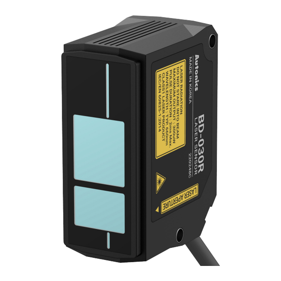
- Page 5 • The label description (left) - label attachment locations (right) for the warning labels on this device are shown below. ■ BD-030R ■ BD-065R ■ BD-100R 18, Bansong-ro 513Beon-gil, Haeundae-gu, Busan, Republic of Korea, 48002 www.autonics.com | +82-2-2048-1577 | sales@autonics.com...
Need help?
Do you have a question about the BD Series and is the answer not in the manual?
Questions and answers