Autonics BD Series Manual
Laser displacement sensor
Hide thumbs
Also See for BD Series:
- User manual (84 pages) ,
- Reference manual (58 pages) ,
- Product manual (6 pages)
Table of Contents
Advertisement
Quick Links
BD Series
Laser Displacement Sensor
▣ Features
● Easy maintenance with separable structure of sensor head/amplifier unit
● Maximum resolution: 1μm (different by models)
● Stable measurement regardless of color or material of the object
● Mutual connection up to 8 amplifier units
: Interference prevention and channel alignment are automatically applied
● Various calculation function (add, subtraction, average)
● Various filter function for stable measurement (average, differential, median)
● Teaching modes configuration (1-point, 2-point) for user environment
● Mounting on DIN-Rail or wall (accessory bracket is needed) is available
● Sensor head IP67 protection structure (patented)
: Korea patent application number 2017-0043925
Please read "Safety Considerations"
in the instruction manual before using.
▣ Manuals
For the detail information and instructions, please refer to user manual for communication, and be sure to follow cautions written
in the technical descriptions (catalog, website).
Visit our website (www.autonics.com) to download manuals.
▣ Model
Max.30
Sensor head
◎ Sensor head
Reference distance
Beam
Model
(Maximum
shape
measurement range)
BD-030
Standard
30mm (20-40mm)
BD-065
Standard
65mm (50-80mm)
BD-100
Standard
100mm (70-130mm)
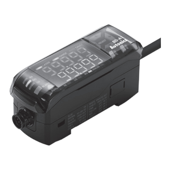
◎ Amplifier unit
Model
Compatible sensor head
BD-A1
BD series sensor head: 1
E-6
Max.30
Extension cable (sold separately)
Spot diameter
Near
Approx. 290×790㎛
(at 25mm)
Approx. 360×1590㎛
(at 55mm)
Approx. 480×1870㎛
(at 80mm)
◎ Extension cable (sold separately)
Model
Length
CID6P-1-SI-BD
1m
CID6P-2-SI-BD
2m
CID6P-5-SI-BD
5m
CID6P-10-SI-BD
10m
Sensor head
: Attaching location of ferrite core
Amplifier unit
Reference
Approx. 240×660㎛
(at 30mm)
Approx. 290×1180㎛
(at 65mm)
Approx. 410×1330㎛
(at 100mm)
Amplifier unit
(unit: mm)
Far
Approx. 190×450㎛
(at 35mm)
Approx. 210×830㎛
(at 75mm)
Approx. 330×950㎛
(at 120mm)
Advertisement
Table of Contents

Related Manuals for Autonics BD Series


Summary of Contents for Autonics BD Series
- Page 1 ▣ Manuals For the detail information and instructions, please refer to user manual for communication, and be sure to follow cautions written in the technical descriptions (catalog, website). Visit our website (www.autonics.com) to download manuals. ▣ Model (unit: mm) : Attaching location of ferrite core Max.30...
-
Page 2: Specifications
IP67 (IEC Standards, except connector of extension cable) structure Material Case: Polycarbonate, Sensing part: Glass, Cable: Polyvinyl chloride Amplifier unit BD Series amplifier unit: 1 compatibility Accessory Ferrite core (made by TDK co. ZCAT2132-1130), Mounting bracket, Bolt, Nut Approval Weight Approx. - Page 3 Protection structure IP40 (IEC Standards) Material Case: Polycarbonate, Cover: Polycarbonate, Cable: Polyvinyl chloride Connection Connector type Sensor head compatibility BD Series sensor head: 1 Accessory Mounting bracket, Side connector Approval Weight Approx. 228g (approx. 126g) ※5 ※1: Power to the load is not included.
-
Page 4: Unit Description
-|Transparent setting guide|- Laser Displacement Sensor ▣ Unit Description ◎ Sensor head Power indicator (red) Indicates whether power supply the sensor head. Receiver Receives reflected laster from the object. Emitter Emits laser to the object to measure the displacement. Emission center line The line and the object should be aligned because the laser is emitted along the line. - Page 5 BD Series ▣ Dimensions ◎ Sensor head (unit: mm) • BD-030 • BD-065/100 42.5 25.3 Optical axis Optical axis of emitter of emitter 19.5 22.5 Ø4.2, 0.5m Ø4.2, 0.5m ● Brackets ● Ferrite core (accessory) • BD-030 • BD-065/100 Ø3.2 2-Ø3.2...
-
Page 6: Installation Procedures
Mount to the panel directly or through the enclosed bracket. mount Refer to '▣ Mounting and Connecting Method' to mount the sensor head. BD series support various settings and functions such as pitch light optimization, Check and apply the function zero adjustment setting, automatic sensitivity setting, calculation through the of amplifier unit. -
Page 7: Mounting Location
BD Series ▣ Mounting Location Select mounting location regarding displacement of the object, reference distance and measurement range. Mount sensor head where the object is located at the reference distance by checking the operation of indicators and displacement value. ◎ Indicator display Check the operation of indicators to know distance between sensor head and the object. - Page 8 -|Transparent setting guide|- Laser Displacement Sensor ▣ Mounting and Connecting Methods ◎ Sensor head Mounting ◎ Connecting to amplifier unit M3 bolt M3 nut Emission center line • Check the mounting position considering emission center line, vibration and shock. ① Connecting: Insert connector of the sensor head into amplifier •...
-
Page 9: Installation Precautions
BD Series ▣ Installation Precautions For stable measurement, mount the sensor head by referring to the below items. ◎ Moving object measurement 1. Object with material / color difference Install the emitter and receiver in parallel to the material or color boundary of the object. -
Page 10: Parameter Setting
-|Transparent setting guide|- Laser Displacement Sensor ▣ Parameter Setting Mode Description Present value (PV) display • Solo: Displays present value (PV). • When using calculation: Displays the result of calculation, and calculation indicator (CALC) of master amplifier unit turns on. Run mode Setting value(SV) display Can change the type of value by the [◀/▶] keys, and each recognition lamp turns on. -
Page 11: Parameter Group
BD Series ▣ Parameter Group • Push the [MODE] key over 2 sec to enter the parameter setting mode. • In the setting mode, change the parameter group by the [◀/▶] keys and enter the group by pushing the [MODE] key. -
Page 12: Error Display
AMP-C Mismatch the version of firmware between sensor head and Please contact the Autonics technical advisory center. amplifier unit. Disconnection of the judgment After turn off the power, check connection of HIGH (black) / GO (gray) / LOW output (orange) wire, and supply the power again. -
Page 13: Cautions During Use
BD Series ▣ Cautions during Use 1. Follow instructions in 'Cautions during Use'. Otherwise, it may cause unexpected accidents. 2. The power supply should be insulated and limited voltage/current or Class 2, SELV power supply device. 3. Do not install where strong magnetic or electric field exist. Otherwise, the resolution may be adversely affected.
Need help?
Do you have a question about the BD Series and is the answer not in the manual?
Questions and answers