Autonics BD Series User Manual
Displacement sensor
Hide thumbs
Also See for BD Series:
- Reference manual (58 pages) ,
- User manual (25 pages) ,
- Manual (14 pages)
Table of Contents
Advertisement
Quick Links
Advertisement
Table of Contents

Related Manuals for Autonics BD Series


Summary of Contents for Autonics BD Series
- Page 1 User Manual Displacement Sensor BD Series MSO-BDU1-V1.1-2002US Thank you for purchasing an Autonics product. This user manual contains information about the product and its proper use, and should be kept in a place where it will be easy to access. www.autonics.com...
- Page 3 Preface Preface Thank you for purchasing Autonics product. Please familiarize yourself with the information contained in the Safety Considerations section before using this product. This user manual contains information about the porduct and its proper use, and should be kept in a place where it will be easy to access.
- Page 4 (www.autonics.com) to download a copy. The manual's content may vary depending on changes to the product's software and other unforeseen developments within Autonics, and is subject to change without prior notice. Upgrade notice is provided through our homepage. ...
- Page 5 User Manual Symbols User Manual Symbols Symbol Description Supplementary information for a particular feature. Failure to follow instructions can result in serious injury or death. Failure to follow instructions can lead to a minor injury or product damage. An example of the concerned feature's use. ※...
-
Page 6: Safety Considerations
Safety Considerations Safety Considerations Following these safety considerations will ensure the safe and proper use of the product and help prevent accidents, as well as minimizing possible hazards. Safety considerations are categorized as Warnings and Cautions, as defined below: Failure to follow the instructions may lead to a serious Warning injury or accident. -
Page 7: Cautions During Use
Cautions during Use Cautions during Use Follow instructions in 'Cautions during Use'. Otherwise, it may cause unexpected accidents. The power supply should be insulated and limited voltage/current or Class 2, SELV power supply device. Do not install where strong magnetic or electric field exist. Otherwise, the resolution may be adversely affected. - Page 8 Table of Contents Table of Contents...
- Page 9 Table of Contents...
- Page 10 Table of Contents PARA1 RSPD SENS NoNC DISP H-SC L-SC H-AN L-AN ERR.OUT FIxOUT PARA2 CALC GAIN FILTER MEDIAN HOLD HOLdT AtLV AtHYS T-MODE TIME PARA3 □ D-IN□ PARA4...
- Page 11 Table of Contents BANK SAVE LOCK INIT...
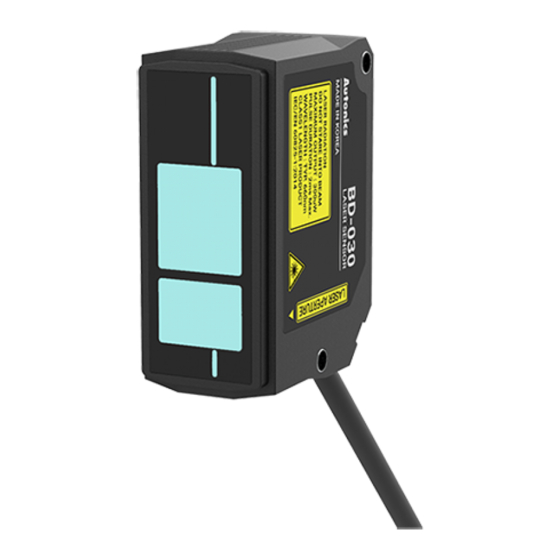
- Page 12 Overview Features Displacement sensor BD Series can accurately measure displacement precisely by high resolution (max. 1㎛, BD-030) and wide measurement range (max. 120mm, BD-100). And consists of a connector type sensor head, an amplifier unit which can be connected up to 8 units, and a communication converter which supports RS-232C, RS-485 communication, to configure the measuring system efficiently.
-
Page 13: Warning Label
1 Overview Warning Label The description on the warning labels attached to the device and the label locations are described below. Label description BD-030 BD-065 BD-100... - Page 14 1 Overview Label attachment locations BD-030 BD-065 BD-100...
- Page 15 1 Overview Components and Sold separately Sensor head Components - BD series sensor head - Bracket for sensor head - Ferrite core - Bolt, Nut 2 sets - Instruction manual Sold separately - External cable for sensor head and amplifier unit...
-
Page 16: Amplifier Unit
1 Overview Amplifier unit Components - BD series amplifier unit - Bracket for amplifier unit - Side connector - Instruction manual Sold separately - External cable for sensor head and amplifier unit... - Page 17 1 Overview Communication converter Components - BD-C series communication converter - Side connector - RS485 connector - Instruction manual Sold separately - SCM-WF48 (Wi-Fi, USB - RS485) - SCM-US48I (USB RS485) - SCM-38I (RS232C - RS485)
- Page 18 1 Overview Please make sure that all of the components are included before using the product. If either component is damaged or missing, please contact our sales office. Components and sold separately image may be slightly different.
-
Page 19: Product Configuration
1 Overview Product configuration Model configuration Sensor head Reference Spot diameter distance Beam Model (Maximum shape measurement Near Reference range) Apporx. Apporx. Apporx. 30mm BD-030 Standard 290×790㎛ 240×660㎛ 190×450㎛ (20-40mm) (at 25mm) (at 30mm) (at 35mm) Apporx. Apporx. Apporx. 65mm BD-065 Standard 360×1590㎛... -
Page 20: External Cable
1 Overview Amplifier unit Model Compatible sensor head BD-A1 BD series sensor head: 1 Communication converter Supported communication Model function BD-CRS RS-232C, RS-485 External cable Model Cable length CID6P-1-SI-BD CID6P-2-SI-BD CID6P-5-SI-BD CID6P-10-SI-BD... -
Page 21: Unit Description
1 Overview Unit Description Sensor head 1. Power indicator (red) Indicates whether power supply the sensor head. 2. Receiver Receives reflected laster from the object. 3. Emitter Emits laser to the object to measure the displacement. 4. Emission center line The line and the object should be aligned because the laser is emitted along the line. - Page 22 1 Overview Amplifier unit 1. Present value (PV) display Displays PV, calculating result (when using calculation), parameter name (when setting parameter). 2. Setting value (SV) display Displays SV (HIGH, LOW, RV, Analog output, Bank), parameter setting value (when setting parameter). The type of displaying SV can be recognized by Setting value (SV) indicator recognition .
- Page 23 1 Overview Communication converter 1. RS485 terminating switch Set the switch to 'RT' when the communication converter is connected to the terminal of RS485 communication connection. 2. RS232C connector A connector for RS232C communication. 3. Status indicator Displays power, communication input/output/error. ...
-
Page 24: Specification
2 Specification Specification Sensor Head Model BD-030 BD-065 BD-100 Near Reference Near Reference Near Reference (25mm) (30mm) (35mm) (55mm) (65mm) (75mm) (80mm) (100mm) (120mm) Spot diameter Approx. Approx. Approx. Approx. Approx. Approx. Approx. Approx. Approx. (Unit: ㎛) 290× 240× 190× 360×... - Page 25 IP67 (IEC Standards, except connector of extension cable) structure Material Case: Polycarbonate, Sensing part: Glass, Cable: Polyvinyl chloride Amplifier unit BD Series amplifier unit: 1 compatibility Accessory Ferrite core (made by TDK co. ZCAT2132-1130), Mounting bracket, Bolt, Nut ᜢ ᜧ...
- Page 26 2 Specification Amplifier Unit Model BD-A1 10-30VDCᜡ ±10% (When connecting BD-C Series Power supply communication converter, 12-30VDCᜡ) Power consumption Max. 2800mW (30VDCᜡ, except connected ) Timing Output reset Control Laser OFF No-voltage input input ※1 Zero adjustment Bank change Judgment output NPN or PNP open collector output (Load current: Max.
- Page 27 2 Specification Sensor head compatibility BD Series sensor head: 1 Accessory Mounting bracket, Side connector ᜢ ᜧ Approval Weight ※4 Approx. 228g (approx. 126g) ※1: Use after assigning to external input line. ※2: It is possible to use among -5-5V, 0-5V, 1-5V, 4-20mA by parameter setting.
- Page 28 2 Specification Communication Converter Model BD-CRS Power supply ※1 Power consumption Max. 2.3W Communication function RS-232C, RS-485 Communication speed 9600, 19200, 38400, 115200bps (default) Indication 4 LED status indicators • Real-time monitoring Function • Executes every BD-Series feature and sets parameter by external device (Master) Ambient -10 to 50℃, Storage: -15 to 60℃...
-
Page 29: Product Connection
3 Product Connection Product Connection Amplifier Unit Connection Control output diagram Judgment (High, Go, Low) and alarm output Analog output (-5-5V, 0-5V, 1-5V, 4-20mA) - Page 30 3 Product Connection Communication Converter Connection RS232C communication RS485 communication Application of system organization Terminating switch Set the switch to 'RT' when the communication converter is connected to the terminal of RS485 communication connection, and set to 'OFF' when it is in the middle of the communication connection.
- Page 31 4 Dimension Dimension (unit: mm) Sensor Head Bracket (accessory) Ferrite core (accessory) Extension cable (sold separately)
- Page 32 4 Dimension Amplifier Unit (unit: mm) Bracket (accessory) Extension cable (sold separately)
- Page 33 4 Dimension Communication Converter (unit: mm)
-
Page 34: Installation Procedures
Mount to the panel directly or through the enclosed bracket. about the Refer to '5.2.1 Mounting’ to mount the sensor head. measurement BD series support various settings and functions such as pitch Check mounting light optimization, zero adjustment setting, automatic method and sensitivity setting, calculation through the amplifier unit. -
Page 35: Mounting Location
5 Installation Sensor Head Mounting Check the mounting position considering emission center line, vibration and shock. Mount to the panel directly or through the bracket by using M3 bolt and nut. Tighten the bolt with 0.5N.m torque when mounting. Mounting Location Select mounting location regarding displacement of the object, reference distance and measurement range. - Page 36 5 Installation Displacement indication The value is displaced more positive (+) as the object is closer to sensor head, more negative value (-) as the object is far from sensor head relative to the origin (0). Indication by distance (unit: mm) Rated Indication...
-
Page 37: Installation Precautions
5 Installation Installation Precautions For stable measurement, mount the sensor head by refering to the below items. Moving object measurement Object with material / color difference Install the emitter and receiver in parallel to the material or color boundary of the object. - Page 38 5 Installation Narrow area or concave object Install the sensor head where the reflected laser beam does not blocked toward the receiver part. Wall mounting Install the sensor head where the reflected laser beam from the wall does not enter the receiver part.
- Page 39 5 Installation Amplifier Unit Mounting with bolt Mounting without DIN rail is possible by using bracket. The method of mounting and detaching with bracket is as same as DIN rail. Mounting on DIN rail Mounting Insert the bottom holder of amplifier unit to 35mm width DIN rail. Push the front part of the unit to arrow direction to mount.
- Page 40 5 Installation Check Point for Installing Sensor Head and Amplifier Unit Ferrite core (accessory) Sensor Head Within 30mm from the sensor head, wind the cable through the inside of the ferrite core three times and mount the ferrite core. ...
- Page 41 5 Installation Connecting amplifier units mutually Remove the side cover at the connecting side. Connect the side connector to the units. After mounting amplifier unit on DIN rail, push it to arrow direction tightly. In case of disconnecting, follow the upper sequence reversely. Distinguishing master/slave amplifier units When the power cable direction is down, the amplifier at the left end is the master unit, and the channel number of slaves increases sequentially to the right.
- Page 42 5 Installation Communication Converter Mounting on DIN rail Mounting Insert bottom holder of communication converter to 35mm width DIN rail. Push the front part of the unit to arrow direction to mount. Detaching Side amplifier unit to direction. Pull the assembly part to direction to detach.
- Page 43 5 Installation Check Point for Installing Communication Converter Connecting to amplifier unit Remove the side cover at the connecting side. Connect the side connector to the units. After mounting amplifier unit and communication unit on DIN rail, push it to arrow direction tightly.
- Page 44 5 Installation Precautions when connecting amplifier unit Mount on DIN rail. Do not supply the power when adding amplifier unit. Supply power to each connected amplifier unit at the same time. Up to 8 amplifier units can be connected, and only 1 calculation function can be performed per 1 group of mutually connected amplifiers.
- Page 45 6 Function Amplifier Unit Function Amplifier Unit Display When Power is ON Displays control output setting screen when connecting a sensor head and supplying power at the first time, or replacing a sensor head. Set the output type as below sequence. Refer to '6.2 Mode Setting' to check the setting range and the reset method.
-
Page 46: Mode Setting
6 Function Amplifier Unit Mode Setting Parameter setting Mode Description Present value (PV) display Solo: Displays present value (PV). When using calculation: Displays the result of calculation, and calculation indicator (CALC) of master amplifier unit Run mode turns on. Setting value(SV) display Displays HIGH setting value, LOW setting value, real distance value (RV), analog output, bank... - Page 47 6 Function Amplifier Unit RUN mode setting 6.2.2.1 Present value (PV) display Solo Displays present value (PV). When using calculation Displays the result of calculation, and calculation indicator (CALC) of master amplifier unit turns on. Refer to ‘7.4.1 Calculation [CALC]’ for the details of calculation’. 6.2.2.2 Setting value(SV) display ...
- Page 48 6 Function Amplifier Unit Exit If there is direction key input [◀] / [▶] / [▲] / [▼] or no key input for 5 sec, returns to run mode. Sensing optimization Optimizes the level of laser emission and receiving sensitivity regarding the object color and environment.
-
Page 49: Sensitivity Adjustment
6 Function Amplifier Unit Sensitivity adjustment The device outputs judgment output by setting the range (HIGH/GO/LOW) and satisfying it. It is possible to set HIGH judgment value and LOW judgment value. HIGH judgment signal is outputted when PV is over HIGH judgment value and LOW judgment signal is outputted when PV is under LOW judgment value. - Page 50 6 Function Amplifier Unit Manual sensitivity adjustment 6.2.5.2 Sets the judgment output (HIGH/GO/LOW) range by manual input. Execution Press [MODE] + [▲] over 2 sec to enter HIGH sensitivity adjustment. Press [MODE] + [▼] over 2 sec to enter LOW sensitivity adjustment. ...
- Page 51 6 Function Amplifier Unit Setting ① '1P' is displayed on setting value (SV) display, push the [AUTO] key within 2 sec. ② After teaching the object for 2 sec, '2P' is displayed on setting value (SV) display, push the [AUTO] key within 2 sec. ③...
- Page 52 7 Parameter Group Amplifier unit Parameter Group Amplifier unit Setting Push the [MODE] key over 2 sec to enter the parameter setting mode. In the setting mode, change the parameter group by the [◀/▶] keys and enter the group by pushing the [MODE] key.
- Page 53 7 Parameter Group Amplifier unit Parameter group 1: Settings related to output type, displacement, PARA1 display and error output. Parameter Setting range Description Default BD-030 L-SC: -5.000 H-SC H-SC: 5.000 BD-065 Display L-SC: -10.000 -99.999 to 99.999 Sets the display scale value. scale H-SC: 10.000 BD-100...
- Page 54 7 Parameter Group Amplifier unit PARA2 Parameter group 2: Settings related to present value Parameter Setting range Description Default ADD-AB Calculatio CALC Sets the type of inner-calculation. SUB-AB Subtraction Averge Sets the level of sensing GAIN Gain 1, 2, 3 sensitivity which increases with level.
- Page 55 7 Parameter Group Amplifier unit PARA2 Parameter group 2: Settings related to present value Parameter Setting range Description Default Set the hysteresis value of Auto trigger level [AtLV]. Auto ※ The parameter is activated AtHYS trigger 0.001 to 99.999 when the value of hold timing 0.001 hysteresis input [T-IN] is over/under...
- Page 56 7 Parameter Group Amplifier unit Parameter group 4: Settings related to user convenience functions PARA4 (This parameter group is common, not saved per bank separately) Parameter Setting range Description Default Set the type of key which lock function is applied. Lock LOCK1 [AUTO], [ZERO] key lock...
- Page 57 7 Parameter Group Amplifier unit Parameter Group 1 [PARA1] Explains items within parameter group 1 related to output type, displacement, display and error output. Refer to ‘7.2 Configuration, Setting range and Factory default’ to check them of each item in group. Response time [RSPD] Sets the data sampling response time.
- Page 58 7 Parameter Group Amplifier unit Output type [NoNC] Selects output type (Normally open, Normally closed) for judgment output(HIGH/GO/LOW). Judgment signal with the type selected in this parameter is outputted according to the judgment output range which is set in 6.2.5 Sensitivity adjustment . PV display [DISP] Sets the type of PV display.
- Page 59 7 Parameter Group Amplifier unit Example setting table Based on sensor head BD-030 model (Reference distance: 30mm, Maximum measurement range: 20 to 40mm, Rated display range: -5 to 5) Setting range Present value (PV) Scale display (SD) H-SC L-SC SD1 PV2 -2.5 -2.5...
- Page 60 7 Parameter Group Amplifier unit Hysteresis [HYS] Sets specific value between ON/OFF of output and delay transition to prevent output instability due to chattering. Refer to below operation timing chart. Hysteresis operation timing chart Analog output scale [H-AN / L-AN] Converts present value (PV) into linear range (Scale) and output it to an analog signal.
- Page 61 7 Parameter Group Amplifier unit Example graph Error output [ERR.OUT] Select the type of output when an error (out of measurement range, lack or saturation of sensitivity), external input output [OUtCLR], filter delay (present value is lower than filter setting value) occurs.
- Page 62 7 Parameter Group Amplifier unit Graph Fixed output [FIxOUT] Outputs the fixed analog value when an error occurs. The parameter is activated when the value of analog output [A-O UT ] is not OFF and error output [ERr.OUT] is Fixed value [FIX] . ...
- Page 63 7 Parameter Group Amplifier unit Parameter Group 2 [PARA2] Explains items within parameter group 2 related to present value. Refer to ‘7.2 Configuration, Setting range and Factory default’ to check them of each item in group. Calculation [CALC] Inner-calculates the measurement value of multiple sensor head and output it. When activating calculation, the mutual interference prevention function and the response speed setting change according to the number of connected amplifiers, and all setting is possible on the master amplifier unit.
- Page 64 7 Parameter Group Amplifier unit Subtraction [SUB-AB] Displays the difference between measurements of 2 sensor heads. Use when measuring step, lifting, bending of the object. Equation: Sensor head A Sensor head B Average [AVG] Displays the average of measurements of 2 or more (up to 8) sensor heads. Use when measuring a flatness of the object.
-
Page 65: Filter [Filter]
Filter [FILTER] Sets the filter to adjust the deviation of the sensor head measurement value. BD series support Average [AVF] , Differential [DIFF] , Median [MEDIAN] filters. Median filter can be set through a separate parameter. Refer to ‘7.4.5 Samples for median [MEDIAN]’. - Page 66 7 Parameter Group Amplifier unit Samples for averaging [AVF] Sets the number to sample for averaging. The amplifier unit calculates the average and outputs it. Only appears when setting ‘Filter [FILTER]’ as ‘Average [AVF]’. Samples for median [MEDIAN] Sets the number to sample for median. The amplifier unit calculates the median and outputs it.
- Page 67 7 Parameter Group Amplifier unit Bottom [BOTTOM] Outputs and maintains the minimum value during the sampling time. The output starts after the sampling ends and remains until the end of the next sampling. Difference [P-P] Outputs and maintains the difference between maximum and minimum value during the sampling time.
- Page 68 7 Parameter Group Amplifier unit Sample [SAMPLE] Outputs and maintains the value of sampling start. The output starts after the sampling ends and remains until the end of the next sampling. Average [AVG] Outputs and maintains the average value during the sampling time. The output starts after the sampling ends and remains until the end of the next sampling.
- Page 69 7 Parameter Group Amplifier unit Hold timing input [HOLdT] Sets the input type of the sampling time for hold function. Only appears when ‘Hold [HOLD]’ is not set to OFF. When setting ‘Over / Under auto trigger mode [AtUP] / [AtDW]’, enters ‘Auto trigger level [AtLV]’, ‘Auto trigger level hysteresis [AtHYS]’...
- Page 70 7 Parameter Group Amplifier unit Auto trigger level [AtLV] Sets the trigger level for auto trigger mode. Only appears when setting ‘Hold timing input [HOLdT]’ to ‘Over / Under auto trigger level [AtUP] / [AtDW]’. When the ‘Display scale [H-SC] / [L-SC] function is applied, the trigger will operate based on the present value (PV).
- Page 71 7 Parameter Group Amplifier unit Off delay [OFD] Holds the judgment output for the set amount of time. Timer value [TIME] Set the time to delay or hold the judgment output. Only appears when setting ‘Timer [T-MODE]’ to ‘On delay [OND]’ or Off delay [OFD]’.
- Page 72 7 Parameter Group Amplifier unit Parameter Group 3 [PARA3] Explains items within parameter group 2 related to external input. Refer to ‘7.2 Configuration, Setting range and Factory default’ to check them of each item in group. External input□ [D-IN□] Assigns the function to each external wire 1 to 4. You can set each function individually or overlay it.
- Page 73 7 Parameter Group Amplifier unit Stop emission [L-OFF] Assigns stop laser emission function. After assigning, laser emission can be stopped by sending signal. Timing chart Minimum input time: 4ms Laser emission ON OFF switch time: 12ms ...
- Page 74 7 Parameter Group Amplifier unit Bank input [BANK-A, BANK-B] Assigns bank load function. After assigning, the bank is activated during the input. Use single wire Activation BANK-A BANK-0 BANK-1 Use double wire Activation BANK-A BANK-B BANK-0 BANK-1 BANK-2 BANK-3 Overlapping BANK-A, B is impossible.
- Page 75 7 Parameter Group Amplifier unit Parameter Group 4 [PARA4] Explains items within parameter group 2 related to user convenience. Refer to ‘7.2 Configuration, Setting range and Factory default’ to check them of each item in group. Parameter group 4 is not saved per bank separately, but used in common. Display direction [DIR] Select display direction (normal, reverse) of amplifier unit to check conveniently regardless of the installation direction.
- Page 76 7 Parameter Group Amplifier unit Saving mode [SAVE] Reduces power consumption by extinguishing the front display lamp when there is no user input for a minute. This fuction is only activated in run mode, all display are on in setting mode. Lock mode [LOCK] Set the key lock function to prevent operating errors.
- Page 77 7 Parameter Group Amplifier unit Initialize [INIT] The bank and all settings can be initialized by selecting parameter. Initialize 1st Select Initialize [INIT] parameter. When pressing [MODE] key, OFF is flashed in SV display. 2nd Select the bank to initialize by pressing [▲] / [▼] keys. 3rd After selecting the bank to initialize and pressing [MODE] key, NO is flashed on SV display.
- Page 78 8 Error Amplifier unit Error Amplifier unit In error status, ERROR is displayed on present value (PV) display. Deal with an error by referring to the below solution of each setting value (SV) display. Setting value Output Reason Solution (SV) display Disconnection of Check the connection between sensor head and...
- Page 79 Check the connection between amplifier units, AMP-C between amplifier and supply the power again. units. Mismatch the version of firmware Please contact the Autonics technical advisory between sensor center. head and amplifier unit. After turn off the power, check connection of Disconnection of the...
- Page 80 9 Communication Converter Communication Converter Communication Setting Switch Default: All switches are OFF Communication speed (Switch 1, 2): Sets RS-232C, RS-485 communication speed to external device. Communication Switch 1 Switch 2 Speed 9600bps 19200bps 38400bps 115200bps Address (Switch 3 to 7): Sets the address of communication converter. It is calculated in binary according to the ON/OFF status of each switch.
- Page 81 9 Communication Converter Parity bit (switch 8, 9): Sets parity bit for RS-232C, RS-485 communication. Parity Switch 8 Switch 9 Even None None Stop bit (switch 10): Sets stop bit for RS-232C, RS-485 communication. Stop bit Switch 10 2bit 1bit...
- Page 82 9 Communication Converter Status Indicator Communication converter Power indicator (POWER): Green, DIsplays power supply. Status Reason Solution Power is supplied After checking the connection between Power is not supplied communication converter and amplifier unit correctly, reconnect the device. Communication output indicator (TX): Green, Displays communication output status from communication converter to external device.
- Page 83 9 Communication Converter Dedicated Device Management Program (atDisplacement) atDisplacement is a comprehensive management program that can be used with Autonics BD-C Series. atDisplacement provides GUI control for easy and convenient parameter setting and monitoring data management of multiple devices. Features ...
- Page 84 * Dimensions or specifications on this manual are subject to change and some models may be discontinued without notice.
Need help?
Do you have a question about the BD Series and is the answer not in the manual?
Questions and answers