Table of Contents
Advertisement
Quick Links
TCD210043AB
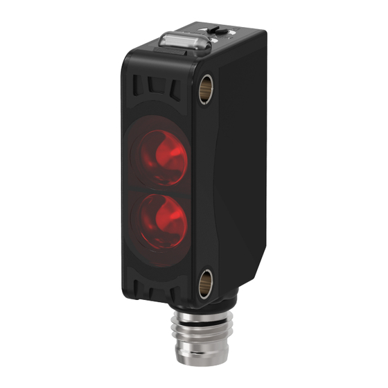
Rectangular
Photoelectric Sensor
BJ Series (Connector type)
PRODUCT MANUAL
For your safety, read and follow the considerations written in the instruction
manual, other manuals and Autonics website.
The specifications, dimensions, etc. are subject to change without notice for product
improvement. Some models may be discontinued without notice.
Features
• Compact size: W 10.6 × H 32 × L 20 mm
• IP67 protection rating (IEC standard)
• Adjuster for selecting Light ON/Dark ON mode
• Built-in sensitivity adjustment adjuster
• Reverse power protection circuit, output short overcurrent protection circuit
• Mutual interference prevention function
• Excellent noise immunity and minimal influence from ambient light
• High performance lens with long sensing distance
• Long sensing distance : Through-beam type 15 m, diffuse reflective type 1 m,
polarized retroreflective type 3 m (MS-2A)
• M.S.R. (Mirror Surface Rejection) function (Polarized retroreflective type)
ᜢ ᜫ
Safety Considerations
• Observe all 'Safety Considerations' for safe and proper operation to avoid hazards.
• symbol indicates caution due to special circumstances in which hazards may occur.
Warning
Failure to follow instructions may result in serious injury or death.
01. Fail-safe device must be installed when using the unit with machinery that
may cause serious injury or substantial economic loss. (e.g., nuclear power
control, medical equipment, ships, vehicles, railways, aircraft, combustion
apparatus, safety equipment, crime/disaster prevention devices, etc.)
Failure to follow this instruction may result in personal injury, economic loss or fire.
02. Do not use the unit in the place where flammable/explosive/corrosive gas,
high humidity, direct sunlight, radiant heat, vibration, impact or salinity
may be present.
Failure to follow this instruction may result in explosion or fire.
03. Do not disassemble or modify the unit.
Failure to follow this instruction may result in fire.
04. Do not connect, repair, or inspect the unit while connected to a power
source.
Failure to follow this instruction may result in fire.
05. Check 'Connections' before wiring.
Failure to follow this instruction may result in fire.
Caution
Failure to follow instructions may result in injury or product damage.
01. Use the unit within the rated specifications.
Failure to follow this instruction may result in fire or product damage.
02. Use a dry cloth to clean the unit, and do not use water or organic solvent.
Failure to follow this instruction may result in fire.
Cautions during Use
• Follow instructions in 'Cautions during Use' . Otherwise, It may cause unexpected
accidents.
• When connecting an inductive load such as DC relay or solenoid valve to the output,
remove surge by using diodes or varistors.
• Use the product after 0.5 sec of the power input.
When using a separate power supply for the sensor and load, supply power to the
sensor first.
• The power supply should be insulated and limited voltage/current or Class 2, SELV
power supply device.
• Wire as short as possible and keep it away from high voltage lines or power lines to
prevent surge and inductive noise.
• When using switching mode power supply (SMPS), ground F.G. terminal and connect
a condenser between 0V and F.G. terminal to remove noise.
• When using a sensor with a noise-generating equipment (e.g., switching regulator,
inverter, and servo motor), ground F.G. terminal of the equipment.
• This unit may be used in the following environments.
- Indoors (in the environment condition rated in 'Specifications')
- Altitude max. 2,000 m
- Pollution degree 3
- Installation category II
Product Components
Sensing type
Through-beam
Product components
Product, instruction manual
Reflector
-
Adjustment screwdriver
× 1
Bracket B
× 2
M3 bolt / nut
× 4
Polarized retroreflective Diffuse reflective
MS-2A
-
× 1
× 1
× 1
× 1
× 2
× 2
Advertisement
Table of Contents

Related Manuals for Autonics BJ Series


Summary of Contents for Autonics BJ Series
- Page 1 - Pollution degree 3 For your safety, read and follow the considerations written in the instruction - Installation category II manual, other manuals and Autonics website. The specifications, dimensions, etc. are subject to change without notice for product Product Components improvement.
- Page 2 MAX (maximum sensitivity): MAX = (B). Set the adjuster at the mid position between (A) and (B) for optimal sensitivity. Dimensions • Unit: mm, For the detailed drawings, follow the Autonics website. Sensor - Reflector: Sensor - Sensing target: At least 0.1 m apart,...
- Page 3 -|Transparent Guide|- Sold Separately: Bracket A Specifications • Unit: mm, For the detailed drawings, follow the Autonics website. Model BJ□-TDT-C-□ BJ3M-PDT-C-□ BJ□-DDT-C-□ Sensing type Through-beam Polarized retroreflective Diffuse reflective 100 mm 300 mm Ø3.4 Sensing distance 10 m 15 m...
- Page 4 -|Transparent Guide|- Sold Separately: Reflector MS Series Sold Separately: Retroreflective Tape MST Series Appearance Size (W × H) Reflectance Sensing type Model Appearance Size (W × H) Approval Packaged unit Sensing type Model Typical Retroreflective MS-2 reflectivity • Retroreflective 50 × 50 mm ᜫ...
- Page 5 Operation area ℓ (mm) • BJ300-DDT • BJ1M-DDT 40 60 Left ← Center → Right Left ← Center → Right Operation area ℓ (mm) Operation area ℓ (mm) 18, Bansong-ro 513Beon-gil, Haeundae-gu, Busan, Republic of Korea, 48002 www.autonics.com | +82-2-2048-1577 | sales@autonics.com...
Need help?
Do you have a question about the BJ Series and is the answer not in the manual?
Questions and answers