Table of Contents
Advertisement
Quick Links
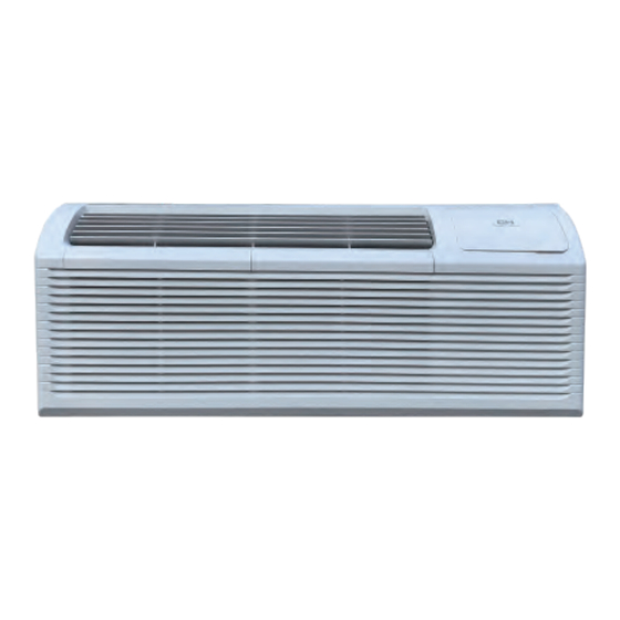
INSTALLATION & USER`S MANUAL
WITH HEAT PUMP AND HEAT STRIP
Model with Heat Pump:
CH-PTHE07HP
CH-PTHE09HP
CH-PTHE12HP
CH-PTHE15HP
For proper operation, please read and keep this manual carefully.
PACKAGED TERMINAL
AIR CONDITIONER
www.cooperandhunter.us
Model with Heat Strip:
CH-PTHE07HS
CH-PTHE09HS
CH-PTHE12HS
CH-PTHE15HS
Advertisement
Table of Contents

Related Manuals for Cooper & Hunter CH-PTHE07HP


Summary of Contents for Cooper & Hunter CH-PTHE07HP
- Page 1 INSTALLATION & USER`S MANUAL PACKAGED TERMINAL AIR CONDITIONER WITH HEAT PUMP AND HEAT STRIP Model with Heat Pump: Model with Heat Strip: CH-PTHE07HP CH-PTHE07HS CH-PTHE09HP CH-PTHE09HS CH-PTHE12HP CH-PTHE12HS CH-PTHE15HP CH-PTHE15HS For proper operation, please read and keep this manual carefully.
-
Page 2: Table Of Contents
CONTENTS 1. SAFETY PRECAUTIONS............... 2. IMPORTANT SAFETY INSTRUCTIONS ..........3. AIR CONDITIONER FEATURES............4. CONTROL PANEL OPERATION............5. DIP SWITCHES CONFIGURATION............6. DIP SWITCHES CONFIGURATION BY PANEL CONTROL....7. WALL THERMOSTAT TERMINAL............8. INSTALLATION..................9. CARE AND CLEANING................. 10. TROUBLESHOOTING................. Read This Manual Inside you will find many helpful hints on how to use and maintain your air conditioner properly. -
Page 3: Safety Precautions
SAFETY PRECAUTIONS To prevent injury to the user or other people and property damage, the following instructions must be followed. Incorrect operation due to ignoring of instructions may cause harm or damage. The seriousness is classified by the following indications. This symbol indicates the possibility of death or serious injury. - Page 4 ! CAUTION Do not clean the air When the air filter is to be Ventilate the room well when conditioner with water. removed, do not touch the used together with a stove, etc. metal parts of the unit. Water may enter the unit and An oxygen shortage may occur.
-
Page 5: Important Safety Instructions
IMPORTANT SAFETY INSTRUCTIONS For your safety WARNING The power supply cord with NOTE Do not store or use gasoline or other flammable vapors and liquids this air conditioner contains a in the vicinity of this or any other appliance. current detection device designed to Avoid fire hazard or electric shock. -
Page 6: Air Conditioner Features
Operation of Current Device(optional) The power supply cord contains a current device that senses damage to the power cord. To test your power supply cord do the following: Plug in the Air Conditioner. The power supply cord will have TWO buttons on the plug head. Press the TEST button, you will notice a click as the RESET button pops out. -
Page 7: Control Panel Operation
CONTROL PANEL OPERATION UP/DOWN BUTTONS (+/-) The control panel keypad will look like the following Fig.1. Push the UP (or DOWN) button to increase (or For some models with REMOTE SIGNALRECEPTOR, the decrease) the set temperature of the unit in cooling or unit can be controlled by the control panel alone or by the heating mode. -
Page 8: Dip Switches Configuration
CONTROL PANEL OPERATION (CONTINUED) Accessory NOTE: This air conditioner is designed to be operated under condition as follows: 64-109°F/18-43°C (64-125°F/18-52°C for Cooling Outdoor temp: special tropical models) operation THIS UNIT IS CONTROLLED BY WALL MOUNTED THERMOSTAT Indoor temp: 62-90°F/17-32°C Note: When the unit displays LC (Pads on Heating Outdoor temp:... - Page 9 DIP SWITCHES CONFIGURATIONS (Optional) Table 1 - DIP SWITCHES CONFIGURATIONS UP(ON) DOWN(OFF) Remarks Electric Heat Only Electric Heat and Pump Heat For Heat Pump unit only Temperature Display in °C Temperature Display in °F Wall Thermostat Enable Control Panel Enable Two configurations (S4*S5) UP*UP:61°F~86°F(16°C~30°C);...
-
Page 10: Dip Switches Configuration By Panel Control
DIP SWITCHES CONFIGURATIONS by PANEL CONTROL (Optional) DIP SWITCHES CONFIGURATIONS by PANEL CONTROL Turn off the unit. LED display window Press the up (+) and down (-) buttons together for 3 High (left) Low (right) seconds to activate the dip switches configurations by panel control (see Fig.4). -
Page 11: Wall Thermostat Terminal
WALL THERMOSTAT TERMINAL (Optional) IMPORTANT: Only trained, qualified personnel Insert the wire connector of the wall thermostat into the should access electrical panel on unit and install relevant terminal according to different shapes as electrical accessories. Please contact your local shown below. - Page 12 WALL THERMOSTAT TERMINAL (Optional) FRONT DESK CONTROL Terminal of PTAC other Wall Thermostat (MODE A) The controller can handle a switch signal from FC(L) and FC(N) input, called front desk control. Input must be 24VAC. If system doesn't receive a 24VAC signal, it will turn unit off;...
-
Page 13: Installation
INSTALLATION HOW TO INSTALL THE UNIT Dimension of air conditioner CAUTION 42in/1067mm There are sharp edges that can cause serious cuts. When lifting the air conditioner, it is HEAVY. Use 2people to lift. 16in/406mm For existing sleeve,you should measure the wall sleeve dimensions. - Page 14 INSTALLATION (CONTINUED) UNIT INSTALLATION (CONTINUED) CAUTION Rotate the vent control lever to either open or close the vent door. (See Fig.9) Do not put obstacles around air-inlet or inside of air-outlet of the unit, such as windowcurtain etc. Vent control lever Always insert the filter securely, clean filter once every two weeks as required.
-
Page 15: Care And Cleaning
CARE AND CLEANING FRONT PANEL AND CASE Removing Air Filter Turn unit off and disconnect power supply. To clean, 2 Air filters use water and a mild detergent. DO NOT use bleach and abrasivers. Some commercial cleaners may Pull up damage the plastic parts. -
Page 16: Troubleshooting
TROUBLESHOOTING POSSIBLE CAUSES SOLUTONS UNIT DOES NOT START Check that plug is plugged securely in wall receptacle. Note: Plug has a test/reset button on it. Make sure that the plug has not Unit may have become unplugged Fuse may have blown tripped. - Page 17 The design and specifications are subject to change without prior notice for product improvement. Consult with the sales agency or manufacturer for details.
Need help?
Do you have a question about the CH-PTHE07HP and is the answer not in the manual?
Questions and answers