Table of Contents
Advertisement
Quick Links
Setup - Operation
PD44 and 1053
Control Box
Meter, mix, and dispense system for precise two-component micro-dispensing of sealants
and adhesives. Not for use in explosive atmospheres.
Important Safety Instructions
Read all warnings and instructions in this
manual before using the equipment.
Save these instructions.
CU8032
EN
Advertisement
Table of Contents

Related Manuals for Graco 1053


Summary of Contents for Graco 1053
- Page 1 Setup - Operation PD44 and 1053 CU8032 Control Box Meter, mix, and dispense system for precise two-component micro-dispensing of sealants and adhesives. Not for use in explosive atmospheres. Important Safety Instructions Read all warnings and instructions in this manual before using the equipment.
-
Page 2: Table Of Contents
PD44 Dispense Valve ..... 6 1053 Dispense Valve ..... . 6 Grounding . -
Page 3: Models
Warnings The following warnings are for the setup, use, grounding, maintenance, and repair of this equipment. The exclamation point symbol alerts you to a general warning and the hazard symbols refer to procedure-specific risks. When these symbols appear in the body of this manual or on warning labels, refer back to these Warnings. Product-specific hazard symbols and warnings not covered in this section may appear throughout the body of this manual where applicable. - Page 4 WARNING PRESSURIZED EQUIPMENT HAZARD Fluid from the equipment, leaks, or ruptured components can splash in the eyes or on skin and cause serious injury. • Follow the Pressure Relief Procedure when you stop spraying/dispensing and before cleaning, checking, or servicing equipment. •...
-
Page 5: Typical Installation
Typical Installation Typical Installation . 1: Typical Installation Key: Control Box Motor PD44 or 1053 Dispense Valve CU8032... -
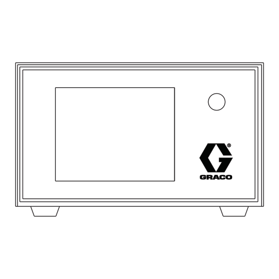
Page 6: Components Identification
Components Identification Components Identification Control Box . 2: Control Box Key: Display B material connection Emergency Stop Switch Servo power connection Remote I/O connection Remote Ethernet connection Sensor, Solenoid valve connection Servo encoder connection A material connection Power assembly Foot Switch connection Cooling Fan CU8032... -
Page 7: Pd44 Dispense Valve
Components Identification PD44 Dispense Valve 1053 Dispense Valve See PD44 dispense valve operation manual 313876 for See 1053 dispense valve operation manual 313812 for detailed dispense valve components identification and detailed dispense valve components identification and instructions. instructions. GREEN YELLOW... -
Page 8: Grounding
Grounding Grounding The equipment must be grounded to reduce the risk of static sparking and electric shock. Electric or static sparking can cause fumes to ignite or explode. Improper grounding can cause electric shock. Grounding provides an escape wire for the electric current. -
Page 9: Hmi Operation
HMI Operation HMI Operation Note: Most of operations of PD44 and 1053 are same, the only difference is System setup screen on page 13. Screen Navigation Diagrams Start Automatic operation Advanced setup screen - 3 main screen (see page 16) -
Page 10: Automatic Operation Main Screen
HMI Operation Automatic operation main 2. Style settings and specified shot size and shot rate • The style setting modes includes two modes: screen external signal control mode and local operation panel control mode. The style setting mode is specified in the advanced settings of the parameter setting screen.The system provides 0-7, a total of 8 groups of style settings. -
Page 11: Automatic Operation Signal Screen
HMI Operation Automatic operation signal Automatic operation external screen signal screen . 6 Automatic operation signal screen . 8 Automatic operation external signal screen (I/O version) In the automatic operation main screen, press the right arrow button to enter the signal screen.The content and functions of this screen are as follows: 1. -
Page 12: System Main Screen
HMI Operation System main screen Manual operation screen . 10 System main screen (I/O version) . 12 Manual operation screen In the system main screen, press ‘Manual’ button,the system enter into the manual operation screen. In this screen, the operator can perform all functions manually. 1. -
Page 13: Setup Screen
1. Basic setup of servo valve • Products type: this control box supports servo valves of type 1053-1’, 1053-2’, 1093 and PD44, if it is needed. • Metering rod size setup: set the diameter of metering rod section. - Page 14 HMI Operation Purge setup screen 3. Reload speed setup Set the reloading speed and ‘Extend’ operations are also performed at this speed. 4. Reload type setup • Reload after each shot: the system automatically completes the reloading after each shot. •...
- Page 15 HMI Operation Advanced setup screen In the setup mode, each screen can be switched to this screen through the advanced button. Advanced setup include three screens. . 18 Advanced setup screen - 2 (I/O version) . 17 Advanced setup screen - 1 The contents and functions of the screen 1 are as follows: 1.
- Page 16 HMI Operation . 20 Advanced setup screen - 3 Password protection setup: when selecting password protection, enter the password, then the operator can enter the setup screen. CU8032...
-
Page 17: Pressure Relief Procedure
1. Turn main air supply valve to the off position. This will bleed air from the system. 2. Close PD44 or 1053 air supply valve to relief air from PD44 or 1053. 3. Perform supply system pressure relief procedure, see related manuals on page 2. -
Page 18: Schematics
Schematics Schematics All electrical wiring must be done by a qualified electrician and comply with all local codes and regulations. CU8032... - Page 19 Schematics JGDL00050 JGDL00050 CU8032...
- Page 20 Schematics JGLG00060 JGLG00060 CU8032...
-
Page 21: Technical Specifications
Technical Specifications Technical Specifications Control Box Metric Power Supply 110 VAC ± 10%, 50/60 Hz Maximum Operating Current 10 A Control Box Size 10.8 in. X 9.8 in. X 5.7 in. 275 mm X 250 mm X 146 mm (Depth X Width X Height), (Depth X Width X Height), not including footing not including footing... -
Page 22: Graco Standard Warranty
With the exception of any special, extended, or limited warranty published by Graco, Graco will, for a period of twelve months from the date of sale, repair or replace any part of the equipment determined by Graco to be defective.
Need help?
Do you have a question about the 1053 and is the answer not in the manual?
Questions and answers