Table of Contents
Advertisement
Quick Links
MCD425A/W VS, MCE425A/W VS, MCC425A/WVS
(See model number configurator on page 2 for details.)
Order parts online
www.follettice.com
Maestro Plus
™
801 Church Lane • Easton, PA 18040, USA
Toll free (877) 612-5086 • +1 (610) 252-7301
www.follettice.com
Ice Machine with RIDE
Installation Instructions for Vision
Technology
™
™
self-contained
01062561R02
Advertisement
Table of Contents

Related Manuals for Follett Maestro Plus MCD425A/W VS


Summary of Contents for Follett Maestro Plus MCD425A/W VS
- Page 1 Maestro Plus Ice Machine with RIDE Technology ™ ™ Installation Instructions for Vision ™ MCD425A/W VS, MCE425A/W VS, MCC425A/WVS (See model number configurator on page 2 for details.) Order parts online www.follettice.com self-contained 801 Church Lane • Easton, PA 18040, USA Toll free (877) 612-5086 •...
- Page 2 Chewblet Ice Machine Model Number Configurations ® Machine Voltage Series Condenser Application Configuration MC Maestro Plus C 208-230/60/1 425 up to Air-cooled, self-contained V Vision™ S RIDE ® Self-contained 454 lbs Chewblet (RIDE remote ice W Water-cooled, H Harmony™ D 115/60/1 Self-contained (206kg) (425 Series)
-
Page 3: Table Of Contents
Contents Unpack .....................................4 Unpack Ice Machine ..............................4 Site Preparation ................................5 Installation site requirements ............................5 Dispenser Preparation ..............................6 Install Vision dispenser ...............................6 Install bin signal ................................6 Install transport tube ..............................7 Mount Ice Machine ................................8 Ice machine in cabinet ..............................9 External Connections ..............................11 Air-cooled ice machines only ............................ 11 Water-cooled ice machines only ..........................11 Bin Stat Cable ................................11 Transport tube installation ............................12 General requirements ............................... -
Page 4: Unpack
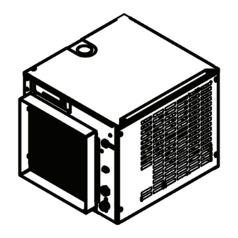
Unpack Carefully unpack and inspect the contents of your Follett ice machine. Unpack Ice Machine Vision • RIDE Technology Maestro Plus... -
Page 5: Site Preparation
Site Preparation Provide drainage, potable water supply and electrical power to within 6 feet (2m) of ice machine in accordance with local and national codes. Outdoor installation is not recommended and will void warranty. Installation site requirements 115 V NEMA 5-15 ➊... -
Page 6: Dispenser Preparation
Dispenser Preparation Install Vision dispenser Refer to Vision Installation, Operation and Service Manual packaged with dispenser for detailed instructions. Install bin signal ➋ Ground Relay in electrical box converts 24 V to contact closure ➊ ➊ 1. Mount the electrical box to the side of the Vision dispenser to establish a ground connection. Note: If a 2 x 4 box is mounted to a non-grounded surface, connect ground wire at an appropriate ground. -
Page 7: Install Transport Tube
Install transport tube Correct installation Incorrect installation § Length of run no more than 20 ft (6 m) § Dips in tube where water can collect § Tube run continuously from ice machine to § Splice or tight bend that restricts ice flow dispenser § Uninsulated tube that results in wet ice and § Insulation on entire run of tube potential dispensing problems § No dips or tight bends § Tube secured in place § No splices 3.3.1 Additional ice transport tube connection specifications for Vision series ice and beverage dispensers Check to make sure bin signal on ice machine control board is switched to 24 V connection. 1. -
Page 8: Mount Ice Machine
Bin thermostat capillary tube mounting Bin thermostat capillary tube mounting Front View, VU155 Front View, VU300 ice tube retaining bracket thermostat thermostat ice tube retaining bracket tabs in ice tube retainer bracket ice tube ice tube engage holes in ice tube and hold tube in place thermostat... -
Page 9: Ice Machine In Cabinet
Ice machine in cabinet Maestro ice machines can be installed undercounter/in-cabinet to fill bins or dispensers using RIDE technology. Care must be taken to ensure proper cabinet venting to avoid recirculation of hot air. Improper venting can cause ice machine outages. Supplied grilles Maestro Ice transport tube ice machine 18.00" (45.7 cm) minimum 1/4" per foot minimum (2 cm per meter) 22.75" (57.8 cm) pitch toward ice machine minimum secure to prevent dips and traps from forming 24.50"... - Page 10 Completed installation with air intake gasket gasket and door in place cabinet door Side View door & gasket must mate directly 22.75" (57.8 cm) 29" Front (74 cm) minimum cutout for supplied air intake grille 12"W x 12"H (30 cm x 30 cm) supplied air drain tube intake grille...
-
Page 11: External Connections
(3/4" MPT). Front View - Water Cooled The rigid drain line from the ice machine must have The rigid drain line from the ice machine must Front View - Air Cooled at least 1/4" per foot (6,4 mm/0,3 m) pitch. have at least 1/" per foot (6,4 mm/0,3 m) pitch. ➋ ➋ § Install ice machine potable water supply § Install ice machine potable water supply (3/8" FPT) (3/8" FPT) . Note: Follett recommends a Follett water filter Note: Follett recommends a Follett water filter system be installed in the ice machine inlet system be installed in the ice machine inlet water line (standard capacity #00130299, high water line (standard capacity #00130299, capacity #00978957, carbonless high capacity high capacity #00978957, carbonless high #01050442). capacity #01050442). ➌ ➍ § Connect cooling water supply and return (3/8" FPT). -
Page 12: Transport Tube Installation
Transport tube installation Incorrect ice transport tube installation can result in wet ice and dispensing problems. Follow guidelines below to ensure correct installation. Call factory for assistance if you are unable to meet these requirements. General requirements § Maximum length of tube run – 20 ft (6 m). Factory approval required for longer runs. § Run tube without dips. § One continuous length of tube; no splices. § Minimum radius of bends in tube – 6" (15.3 cm) inside radius. § Maximum number of bends – 6. § Insulation on entire run of ice tube. Procedure 1. Install supplied insulation on entire length of tube. 2. Remove ice machine top panel. 3. Select side, rear or top knockout in ice machine cabinet for tube entrance and install bushing. 4. Run insulated tube without dips between dispenser and ice machine and secure in place. 5. Slide end of transport tube and insulation through bushing and run to nozzle. 6. Cut tube to that length. 7. Pull insulation back and slip supplied hose clamp over end of transport tube. ➊ ➋ 8. Heat end of transport tube in cup of 160 F (71 C) hot water to soften and spread with pliers before making connection to ease assembly. ➌... -
Page 13: Ride Model Ice Machine Start Up Procedure
RIDE model ice machine start up procedure The start-up procedure below is intended to ensure that ice machine is operating properly after installation has been made. Check each item listed and call factory immediately for assistance if you experience problems with unit. NOTICE! § Ice machine MUST be sanitized prior to operation! § Consult Operation and Service Manual provided with ice machine for sanitizing instructions. Before turning on power 1. Turn on water to ice machine. 2. Check that hose clamp securely holds ice transport tube on evaporator port. After turning on power 1. Turn on power to ice machine and confirm that gearmotor, fan motor and compressor start immediately. 2. Check that ice begins to enter dispenser bin area within approximately 10 minutes. 3. Put ice against bin level thermostat in dispenser bin and check that compressor and gear motor shut down immediately after thermostat opens. Fan will continue to run for an additional 10 minutes. 4. Check that ice machine comes back on in approximately 20 minutes (bin signal must be present). Vision • RIDE Technology Maestro Plus... - Page 14 Vision • RIDE Technology Maestro Plus...
- Page 15 Vision • RIDE Technology Maestro Plus...
- Page 16 Maestro Plus and Harmony are trademarks of Follett LLC. Follett, Chewblet and RIDE are registered trademarks of Follett LLC, registered in the US. 801 Church Lane • Easton, PA 18040, USA Toll free (877) 612-5086 • +1 (610) 252-7301 01062561R02 www.follettice.com...
Need help?
Do you have a question about the Maestro Plus MCD425A/W VS and is the answer not in the manual?
Questions and answers