Advertisement
Quick Links
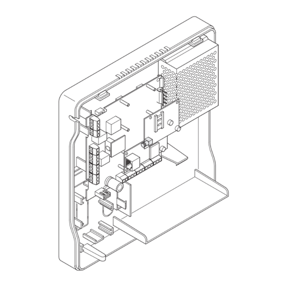
GSM COMMUNICATION EXPANSION MODULE
Fitting the GSM module
√ Make sure the card on which you intend to fi t the module is not connected to the
power supply.
IMPORTANT: any operation involving the assembly or disassembly of expansion
modules must be performed with all input power (from power supply unit or
battery) OFF, in order to avoid permanently damaging the expansion module you
intend to add or remove, as well as the control panel card.
Insert the plastic spacers in the predisposed holes. Then, taking care to plug the module connector into
the control unit connector designated MOD5 correctly, apply suffi cient pressure to engage the spacers in
the GSM expansion card and plug the connector in almost completely.
ART. 30001301
1
1
Advertisement

Related Manuals for Comelit 30001301


Summary of Contents for Comelit 30001301
- Page 1 GSM COMMUNICATION EXPANSION MODULE ART. 30001301 Fitting the GSM module √ Make sure the card on which you intend to fi t the module is not connected to the power supply. IMPORTANT: any operation involving the assembly or disassembly of expansion...
- Page 2 } Once you have fi tted the module correctly, connect the antenna to the respective connector. IMPORTANT: Place the antenna in the special slot under the battery (as shown in the fi gure). CAUTION: If the position of the control panel does not allow the reception of a GSM signal suffi...
- Page 3 GSM telephone dialler: antenna, SIM card and indicator lights Once plugged into the control unit card, the GSM dialler needs only to be connected to the antenna. The antenna must be correctly connected and its connector must be fully tightened. Connecting the antenna Connect the antenna that you intend to use by tightening the connector on the cable to the gold-coloured connector on the GSM module.
- Page 4 DL5, red, radio connection status. Has 5 different statuses: OFF and 4 different levels of strength (from control panel Fw version 2.2.1, this indication is only visible with “service” jumper Jp7 inserted). OFF: indicates that there is no signal (e.g. antenna or SIM card missing). ON: four different levels of strength indicate the level of GSM signal received.
Need help?
Do you have a question about the 30001301 and is the answer not in the manual?
Questions and answers