Table of Contents
Advertisement
Installation, Operation, and Maintenance
VariTrane™ ™ Variable Air Volume
(VAV) Terminal Air Units
Shutoff, Fan Powered, and CoolSense™
Sensible Cooling
S S i i n n g g l l e e - - D D u u c c t t : : VCCF, VCEF, VCWF
D D u u a a l l - - D D u u c c t t : : VDDF
F F a a n n - - P P o o w w e e r r e e d d : : VPCF, VPEF, VPWF, VSCF, VSEF, VSWF
F F a a n n - - P P o o w w e e r r e e d d L L o o w w H H e e i i g g h h t t : : LPCF, LPEF, LPWF, LSCF, LSEF, LSWF
C C h h i i l l l l e e d d W W a a t t e e r r S S e e n n s s i i b b l l e e C C o o o o l l i i n n g g T T e e r r m m i i n n a a l l U U n n i i t t s s : : LDCF, LDEF, LDWF
Only qualified personnel should install and service the equipment. The installation, starting up, and servicing of heating, ventilating, and air-conditioning
equipment can be hazardous and requires specific knowledge and training. Improperly installed, adjusted or altered equipment by an unqualified person
could result in death or serious injury. When working on the equipment, observe all precautions in the literature and on the tags, stickers, and labels that
are attached to the equipment.
September 2021
S S A A F F E E T T Y Y W W A A R R N N I I N N G G
V V A A V V - - S S V V X X 0 0 8 8 R R - - E E N N
Advertisement
Table of Contents

Related Manuals for Trane VariTrane VCCF


Summary of Contents for Trane VariTrane VCCF
- Page 1 Installation, Operation, and Maintenance VariTrane™ ™ Variable Air Volume (VAV) Terminal Air Units Shutoff, Fan Powered, and CoolSense™ Sensible Cooling S S i i n n g g l l e e - - D D u u c c t t : : VCCF, VCEF, VCWF D D u u a a l l - - D D u u c c t t : : VDDF F F a a n n - - P P o o w w e e r r e e d d : : VPCF, VPEF, VPWF, VSCF, VSEF, VSWF F F a a n n - - P P o o w w e e r r e e d d L L o o w w H H e e i i g g h h t t : : LPCF, LPEF, LPWF, LSCF, LSEF, LSWF...
- Page 2 A A L L W W A A Y Y S S r r e e f f e e r r t t o o a a p p p p r r o o p p r r i i a a t t e e S S a a f f e e t t y y D D a a t t a a impact to the environment. Trane advocates the...
- Page 3 , , a a n n d d s s p p r r a a y y i i n n g g m m a a y y g g e e n n e e r r a a t t e e f f i i b b e e r r site are NOT covered by the Trane warranty.
- Page 4 This document and the information in it are the • Running edits. property of Trane, and may not be used or reproduced in whole or in part without written permission. Trane reserves the right to revise this publication at any time, and to make changes to its content without obligation to notify any person of such revision or change.
-
Page 5: Table Of Contents
Table of Contents Model Numbers ......6 Chilled Water Sensible Cooling Terminal Units Moisture Sensor Installation ..26 Single-Duct VAV Units . -
Page 6: Model Numbers
Digit 12, 13, 14, 15 — Controls DD43 = UC400 DDC- Basic (Water heat- Staged) Modulating) DD75 = UC210 DDC- Basic (Electric heat- DD00 = Trane Actuator Only and Enclosure DD44 = UC400 DDC- Basic (Electric heat- PWM) DD01 = UCM4 Cooling Only Control Staged) DD76 = UC210 DDC Ventilation flow- cooling DD02 = UCM4 N.C. - Page 7 B = Spring Return, Normally Closed Digit 24 — Disconnect Switch F = 1” Double Wall C = Belimo™ Actuator G = 3/8” Closed-cell G = Trane Analog Actuator (UC210 or UC400 0 = None only) Digit 17, 18— Not Used W = With Digit 35 —...
- Page 8 M M o o d d e e l l N N u u m m b b e e r r s s Digit 37 — Integral Attenuator with Cam Lock Bottom Access 0 = None 1 = Attenuator and bottom access - left side controls 2 = Attenuator and bottom access - right side controls...
-
Page 9: Dual-Duct Vav Units
0 = Standard Digit 12, 13, 14, 15 — Controls A = Belimo™ Actuator 0 = None B = Trane Analog Actuator (UC400 only) DD00 = Trane Actuator Only 1 = 120/24V, 50 VA DD01 = Dual UCM4.2 Cooling Only Control Digit 35 —... -
Page 10: Descriptions
T =06SQ Fan (1850 nom cfm) FM00 = Other Actuator and Control Modulating SCR) U = 07SQ Fan (2000 nom cfm) FM01 = Trane Supplied Actuator, Other Ctrl DD66 = UC400 Basic plus- Local (Electric heat-Modulating SCR) Remote (Staged EH) Digit 10, 11— Design Sequence... - Page 11 1 = Flanged G = 347/60/1 A = Belimo™ Actuator 2 = Slip–and-Drive Connection H = 575/60/3 G = Trane Analog Actuator (UC210 or UC400 J = 380/50/3 only) Digit 20— Attenuator K = 120/60/1 Digit 35 — Wireless Sensors 0 = None Note: Digit K not available wit low height.
- Page 12 M M o o d d e e l l N N u u m m b b e e r r s s Digit 39 — Water Valve 0 = None 1 = HW Valve 0.7 Cv 2 = HW Valve 2.7 Cv 5 = Analog HW Valve, Field Provided (UC210 or UC400 only) 6 = HW Valve 1.7 Cv...
-
Page 13: Chilled Water Sensible Cooling Terminal
ENCL = Shaft Only in Enclosure Digit 32 — Airflow Switch E = 2 Row Premium, Hot Coil on Discharge, FM00 = Other Actuator and Control FM01 = Trane Supplied Actuator, Other F = 2 Row Premium, Hot Coil on Discharge, 0 = None Control... - Page 14 M M o o d d e e l l N N u u m m b b e e r r s s Digit 36 — Pre-wired Factory Digit 43 — Chilled Water Piping Solutions Package 0 = None 0 = None 1 = Discharge Temperature Sensor (DTS) A = 2–Way Automatic Balancing...
-
Page 15: Unit Information
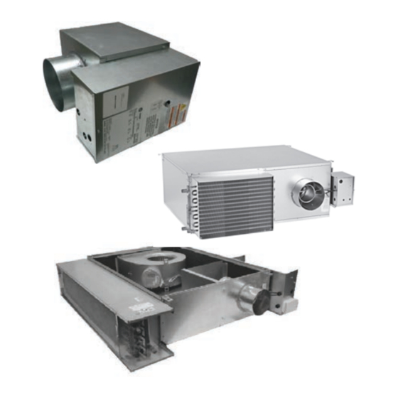
Unit Information Single Duct VAV Units Typical Single Duct VAV Units Figure 1. Typical single duct unit; VCCF VCWF, VCEF The basic unit consists of a sheet metal casing with an air valve, which is used to modulate the air being delivered into the occupied zone. -
Page 16: Dual-Duct Vav Units
The typical result is that the air flowing into the zone stays at a constant flow whether the unit is heating or cooling. Factory-installed Trane unit controls available include; • UC400 — one required per unit •... -
Page 17: Units
U U n n i i t t I I n n f f o o r r m m a a t t i i o o n n Figure 5. Low height series: LSEF (top) and low fan is turned on as the first stage of heat. The fan height parallel: LPCF (bottom) delivers plenum air from above the occupied space to the unit outlet, which is mixed with primary air and... - Page 18 These terminal units can be configured with either a hot water coil or electric heater mounted at the unit discharge. The function of the Trane chilled water sensible cooling terminal units is a little different than traditional VAV VAV-SVX08R-EN...
-
Page 19: Unit Installation
Unit Installation Single-Duct VAV Units W W A A R R N N I I N N G G H H a a z z a a r r d d o o u u s s V V o o l l t t a a g g e e w w / / C C a a p p a a c c i i t t o o r r s s ! ! Figure 10. -
Page 20: Fan-Powered Vav Units And Chilled
U U n n i i t t I I n n s s t t a a l l l l a a t t i i o o n n Fan-Powered VAV Units and Table 1. Dual duct VAV unit hanger location dimensions Chilled Water Sensible Cooling Inlet... - Page 21 U U n n i i t t I I n n s s t t a a l l l l a a t t i i o o n n Figure 13. Series hanger bracket locations Flow Ring Flow Ring tubing tubing...
- Page 22 U U n n i i t t I I n n s s t t a a l l l l a a t t i i o o n n Figure 14. Low-height parallel DS02/PS02 39.1 39.1 [993] [993] Primary Airflow Primary Airflow...
- Page 23 U U n n i i t t I I n n s s t t a a l l l l a a t t i i o o n n Figure 15. Low-height series DS02/PS02/DS03 w/hot water or electric heat 32.3 [821] 32.3...
-
Page 24: Bracket Locationschilled Water Sensible Cooling Terminal
U U n n i i t t I I n n s s t t a a l l l l a a t t i i o o n n Duct Connections Bracket Locations Chilled Water Sensible Cooling Terminal All VariTrane™... -
Page 25: Discharge Duct Temperature Sensor
U U n n i i t t I I n n s s t t a a l l l l a a t t i i o o n n single row coils. For multi-row coils, always plumb damage. -
Page 26: Installation
For proper service, it is recommended that at least 3 unit. Trane chilled water sensible cooling terminal units inches” of side clearance be provided to service and are built with a drip pan located beneath and above the access single-duct and dual-duct terminals units. -
Page 27: Control
U U n n i i t t I I n n s s t t a a l l l l a a t t i i o o n n action is determined by the auxiliary temperature temperature and the zone temperature +10°F (5.5°C) sensor located on TB3-5 and TB3-6 terminals on the [zone temperature <... -
Page 28: Weights
U U n n i i t t I I n n s s t t a a l l l l a a t t i i o o n n Weights Table 5. Single-duct units— lb/kg Single Wall Dual Wall Unit Size VCWF... - Page 29 U U n n i i t t I I n n s s t t a a l l l l a a t t i i o o n n Table 7. Parallel fan-powered units — lb/kg Single Wall Dual Wall VPxF Unit Size...
- Page 30 U U n n i i t t I I n n s s t t a a l l l l a a t t i i o o n n Table 8. Series fan–powered units — lb/kg (continued) Single Wall Dual Wall VSxF...
- Page 31 U U n n i i t t I I n n s s t t a a l l l l a a t t i i o o n n Table 10. Low–height series units — lb/kg Single Wall Dual Wall LSxF Unit Size...
-
Page 32: Unit Setup
Unit Setup Figure 21. Flow sensor ΔP vs. airflow delivery 8" x 12" 6” 8" 14" 16" 10" 12" 16" x 24" 4” 5” 0.01 1,000 10,000 Airflow (CFM) Fan Motor Amperage Reference unit submittal data and motor nameplate. Adjusting the SCR Motor Speed Control In order to make units more convenient and efficient to balance, an SCR (silicone control rectifier) is provided... -
Page 33: Electrically Commutated Motor
25, p. Figure 25. ECM control board 2-10 VDC input signal shunt placement Trane offers an energy efficient ECM as a motor option. The optional Tracer® UC210 and UC400 unit controllers directly interface with the ECM to control fan airflow and fan on/off control. - Page 34 100% 10.0 10.0 % setting from Trane unit controller via pulse width modulating signal or ECM control board with manual fan speed adjust setting. ECM control board with 0-10 VDC fan modulation input and separate fan on/off binary input required.
- Page 35 1222 2100 100% 10.0 10.0 % setting from Trane unit controller via pulse width modulating 1301 signal or ECM control board with manual fan speed adjust setting. 1379 ECM control board with 0-10 VDC fan modulation input and separate fan on/off binary input required.
- Page 36 2050 100% 10.0 10.0 1010 % setting from Trane unit controller via pulse width modulating 1071 signal or ECM control board with manual fan speed adjust setting. ECM control board with 0-10 VDC fan modulation input and separate 1133 fan on/off binary input required.
- Page 37 1960 1300 100% 10.0 10.0 % setting from Trane unit controller via pulse width modulating 2050 signal or ECM control board with manual fan speed adjust setting. 2140 1010 ECM control board with 0-10 VDC fan modulation input and separate fan on/off binary input required.
-
Page 38: Wiring Diagrams
Wiring Diagrams N N o o t t e e s s : : See programming guides listed below for • VV550: VAV-SVP01*-EN detailed class II low voltage unit controls wiring information on the following: • UCM 4.2: VAV-SVX01*-EN • UC400: VAV-SVX07*-EN •... -
Page 39: Box
W W i i r r i i n n g g D D i i a a g g r r a a m m s s Wiring — Electric Heater Control Box Figure 26. Single duct , single phase, 1 leg, 3 stages VAV-SVX08R-EN... - Page 40 W W i i r r i i n n g g D D i i a a g g r r a a m m s s Figure 27. Single duct, single phase, 2 legs, 3 stages VAV-SVX08R-EN...
- Page 41 W W i i r r i i n n g g D D i i a a g g r r a a m m s s Figure 28. Single duct, three phase, delta, 3 stages VAV-SVX08R-EN...
- Page 42 W W i i r r i i n n g g D D i i a a g g r r a a m m s s Figure 29. Single duct, single phase, SCR, 1 leg, 1 stage VAV-SVX08R-EN...
- Page 43 SINGLE PHASE INDICATE COMPONENTS THAT ARE OPTIONAL OR GROUPED HIGH TEMPERATURE CUTOUT (AUTO RESET) LINE VOLTAGES TOGETHER. SOLID LINES INDICATE WIRING BY TRANE. SUPPLY AIR PROVING SWITCH CONTROL POWER TRANSFORMER ALL FIELD WIRING MUST BE IN ACCORDANCE WITH THE NATIONAL ELECTRIC CODE (NEC), STATE AND LOCAL REQUIREMENTS.
- Page 44 W W i i r r i i n n g g D D i i a a g g r r a a m m s s Figure 31. Single duct, three phase, delta, SCR, 1 stage VAV-SVX08R-EN...
- Page 45 W W i i r r i i n n g g D D i i a a g g r r a a m m s s Figure 32. Single duct, single phase, 1 leg VAV-SVX08R-EN...
- Page 46 W W i i r r i i n n g g D D i i a a g g r r a a m m s s Figure 33. Fan powered, single phase, 1 leg, 2 stages VAV-SVX08R-EN...
- Page 47 W W i i r r i i n n g g D D i i a a g g r r a a m m s s Figure 34. Fan powered, single phase, 2 legs, 2 stages VAV-SVX08R-EN...
- Page 48 W W i i r r i i n n g g D D i i a a g g r r a a m m s s Figure 35. Fan powered, three phase, wye, 2 stages VAV-SVX08R-EN...
- Page 49 W W i i r r i i n n g g D D i i a a g g r r a a m m s s Figure 36. Fan powered, single phase, 1 leg, 2 stages VAV-SVX08R-EN...
- Page 50 W W i i r r i i n n g g D D i i a a g g r r a a m m s s Figure 37. Fan powered, single phase, 2 legs, 2 stages VAV-SVX08R-EN...
- Page 51 W W i i r r i i n n g g D D i i a a g g r r a a m m s s Figure 38. Fan powered, three phase, wye, 2 stages VAV-SVX08R-EN...
-
Page 52: Control Box Wiring
W W i i r r i i n n g g D D i i a a g g r r a a m m s s Control Box Wiring Figure 39. Single duct control box VAV-SVX08R-EN... - Page 53 W W i i r r i i n n g g D D i i a a g g r r a a m m s s Figure 40. Fan-powered units with PSC motors VAV-SVX08R-EN...
- Page 54 W W i i r r i i n n g g D D i i a a g g r r a a m m s s Figure 41. Fan-powered units with ECM motor VAV-SVX08R-EN...
- Page 55 W W i i r r i i n n g g D D i i a a g g r r a a m m s s Figure 42. Fan-powered units with ECV motor VAV-SVX08R-EN...
- Page 56 W W i i r r i i n n g g D D i i a a g g r r a a m m s s Figure 43. Fan-powered, old style VAV-SVX08R-EN...
- Page 57 W W i i r r i i n n g g D D i i a a g g r r a a m m s s Figure 44. Fan-powered, ECM, old style VAV-SVX08R-EN...
- Page 58 W W i i r r i i n n g g D D i i a a g g r r a a m m s s Figure 45. Fan-powered, low-height incl 10SQ, old style Fan-Powered Low-Height Control Box Fan-Powered Low-Height Control Box Duct Pressure Switch Option MOTOR 2...
- Page 59 W W i i r r i i n n g g D D i i a a g g r r a a m m s s Figure 46. Fan-powered, low-height incl 10SQ, ECM, old style Fan-Powered Low-Height Control Box Fan-Powered Low-Height Control Box w/ ECM with Electronic or DDC Controls w/ ECM...
-
Page 60: Maintenance
Maintenance Fan Motor Replacement Periodic maintenance of the VariTrane™ product is minimal, but necessary for efficient operation. Routine W W A A R R N N I I N N G G maintenance consists of inspecting/replacing the air filters of the fan-powered terminals. H H a a z z a a r r d d o o u u s s V V o o l l t t a a g g e e w w / / C C a a p p a a c c i i t t o o r r s s ! ! F F a a i i l l u u r r e e t t o o d d i i s s c c o o n n n n e e c c t t p p o o w w e e r r a a n n d d d d i i s s c c h h a a r r g g e e Motors... -
Page 61: Scr Assembly
M M a a i i n n t t e e n n a a n n c c e e SCR Assembly overheating during normal operation. The SCR assembly must always be mounted with the heat sink SCR solid state relays are used to switch a single heater fins oriented vertically (see above) with a minimum stage on and off. - Page 62 N N o o t t e e s s VAV-SVX08R-EN...
- Page 63 N N o o t t e e s s VAV-SVX08R-EN...
- Page 64 For more information, please visit trane.com or tranetechnologies.com. Trane has a policy of continuous product and product data improvements and reserves the right to change design and specifications without notice. We are committed to using environmentally conscious print practices.
Need help?
Do you have a question about the VariTrane VCCF and is the answer not in the manual?
Questions and answers