Advertisement
TCD210236AC
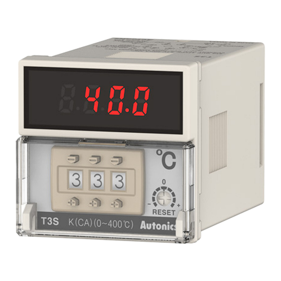
Thumbwheel Switch
Temperature Controllers
T3 / T4 Series
PRODUCT MANUAL
For your safety, read and follow the considerations written in the instruction
manual, other manuals and Autonics website.
The specifications, dimensions, etc are subject to change without notice for product
improvement Some models may be discontinued without notice.
Features
• Various control output options : relay, SSR drive, current
• 2 independent set points and control outputs for heating and cooling control (T4LP)
• Various sizes (W48×H48, W48×H96, W72×H72, W96×H96 mm)
ᜫ
Safety Considerations
• Observe all 'Safety Considerations' for safe and proper operation to avoid hazards.
• symbol indicates caution due to special circumstances in which hazards may occur.
Warning
Failure to follow instructions may result in serious injury or death
01. Fail-safe device must be installed when using the unit with machinery that
may cause serious injury or substantial economic loss.(e.g. nuclear power
control, medical equipment, ships, vehicles, railways, aircraft, combustion
apparatus, safety equipment, crime/disaster prevention devices, etc.)
Failure to follow this instruction may result in personal injury, economic loss or fire.
02. Do not use the unit in the place where flammable/explosive/corrosive gas,
high humidity, direct sunlight, radiant heat, vibration, impact or salinity
may be present.
Failure to follow this instruction may result in explosion or fire.
03. Install on a device panel to use.
Failure to follow this instruction may result in electric shock.
04. Do not connect, repair, or inspect the unit while connected to a power
source.
Failure to follow this instruction may result in fire or electric shock.
05. Check 'Connections' before wiring.
Failure to follow this instruction may result in fire.
06. Do not disassemble or modify the unit.
Failure to follow this instruction may result in fire or electric shock.
Caution
Failure to follow instructions may result in injury or product damage
01. When connecting the power input and relay output, use AWG 20 (0.50 mm
cable or over, and tighten the terminal screw with a tightening torque of 1.0
N m.
When connecting the sensor input and communication cable without
dedicated cable, use AWG 28 to 16 cable and tighten the terminal screw with
a tightening torque of 1.0 N m.
Failure to follow this instruction may result in fire or malfunction due to contact
failure.
02. Use the unit within the rated specifications.
Failure to follow this instruction may result in fire or product damage
03. Use a dry cloth to clean the unit, and do not use water or organic solvent.
Failure to follow this instruction may result in fire or electric shock.
04. Keep the product away from metal chip, dust, and wire residue which flow
into the unit.
Failure to follow this instruction may result in fire or product damage.
Cautions during Use
• Follow instructions in 'Cautions during Use' . Otherwise, it may cause unexpected
accidents.
• Check the polarity of the terminals before wiring the temperature sensor. For RTD
temperature sensor, wire it as 3-wire type, using cables in same thickness and length.
For thermocouple (TC) temperature sensor, use the designated compensation wire for
extending wire.
• Keep away from high voltage lines or power lines to prevent inductive noise. In case
installing power line and input signal line closely, use line filter or varistor at power line
and shielded wire at input signal line. Do not use near the equipment which generates
strong magnetic force or high frequency noise.
)
2
Advertisement
Table of Contents

Subscribe to Our Youtube Channel
Related Manuals for Autonics T3 Series


Summary of Contents for Autonics T3 Series
- Page 1 For your safety, read and follow the considerations written in the instruction • Follow instructions in ‘Cautions during Use’ . Otherwise, it may cause unexpected manual, other manuals and Autonics website. accidents. The specifications, dimensions, etc are subject to change without notice for product •...
-
Page 2: Ordering Information
02) Dual setting output of the T4LP is fixed as relay output and, it is also available as alarm output. F: Fahrenheit (℉) 03) Certification attainment may vary depending on the model. Check the certification on the Autonics website. • Contact us for temperature unit ℉ model. -
Page 3: Unit Descriptions
-|Transparent Guide|- Unit Descriptions Connections ■ T3S SSR OUT: 12VDC± ± 2V 20mA Max. RELAY OUT: CURRENT OUT: DC4-20mA 250VAC 5A 1c Load 500Ω Ω Max. 30VDC 5A 1c RESISTIVE LOAD SENSOR SOURCE 100-240VAC 50/60 Hz 5VA ■ T4M/T4MA SENSOR 1. - Page 4 ① ① Dimensions ② ② • Unit: mm, For the detailed drawings, follow the Autonics website. • Below is based on T3S Series. Press the 8-pin plug with your thumb. Insert Press the peaks (①) on both side with your a flat head driver to the groove (①) and uplift...
- Page 5 Segment Table The segments displayed on the product indicate the following meanings. It may differ depending on the product. 7 Segment 11 Segment 12 Segment 16 Segment 18, Bansong-ro 513Beon-gil, Haeundae-gu, Busan, Republic of Korea, 48002 www.autonics.com | +82-2-2048-1577 | sales@autonics.com...
Need help?
Do you have a question about the T3 Series and is the answer not in the manual?
Questions and answers