Table of Contents
Advertisement
TCD210225AA
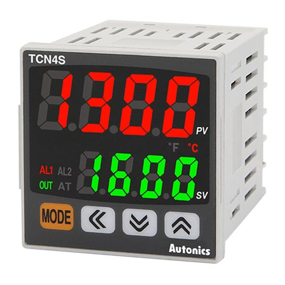
Dual Display PID
Temperature Controllers
TCN Series
PRODUCT MANUAL
For your safety, read and follow the considerations written in the instruction
manual, other manuals and Autonics website.
The specifications, dimensions, etc are subject to change without notice for product
improvement Some models may be discontinued without notice.
Features
• Dual digital display (PV/SV)
• 100ms high-speed sampling rate and ±0.5% display accuracy
• Switch between relay output and SSR drive output (patent) *
• SSR drive output (SSRP function) control options : ON/OFF control, cycle control,
phase control
• Compact design with large display panels for easier reading
• Connector plug types offer easier wiring and maintenance (TCN4S-□-P)
*
Korea Patent Registration 10-1002582, U.S.A. Patent Registration 8645000, Japan Patent Registration 3184816,
China Patent Registration ZL200980111733.X, Vietnam Patent Registration 1-0012131, India Patent Registration
291573, Indonesia Patent Registration IDP0032166
ᜢ ᜧ ᜫ
Safety Considerations
• Observe all 'Safety Considerations' for safe and proper operation to avoid hazards.
• symbol indicates caution due to special circumstances in which hazards may occur.
Warning
Failure to follow instructions may result in serious injury or death
01. Fail-safe device must be installed when using the unit with machinery that
may cause serious injury or substantial economic loss.(e.g. nuclear power
control, medical equipment, ships, vehicles, railways, aircraft, combustion
apparatus, safety equipment, crime/disaster prevention devices, etc.)
Failure to follow this instruction may result in personal injury, economic loss or fire.
02. Do not use the unit in the place where flammable/explosive/corrosive gas,
high humidity, direct sunlight, radiant heat, vibration, impact or salinity
may be present.
Failure to follow this instruction may result in explosion or fire.
03. Install on a device panel to use.
Failure to follow this instruction may result in fire or electric shock.
04. Do not connect, repair, or inspect the unit while connected to a power
source.
Failure to follow this instruction may result in fire or electric shock.
05. Check 'Connections' before wiring.
Failure to follow this instruction may result in fire.
06. Do not disassemble or modify the unit.
Failure to follow this instruction may result in fire or electric shock.
Caution
Failure to follow instructions may result in injury or product damage
01. When connecting the power input and relay output, use AWG 20 (0.50 mm
cable or over, and tighten the terminal screw with a tightening torque of 0.74
to 0.90 N m.
When connecting the sensor input and communication cable without
dedicated cable, use AWG 28 to 16 cable and tighten the terminal screw with
a tightening torque of 0.74 to 0.90 N m.
Failure to follow this instruction may result in fire or malfunction due to contact
failure.
02. Use the unit within the rated specifications.
Failure to follow this instruction may result in fire or product damage
03. Use a dry cloth to clean the unit, and do not use water or organic solvent.
Failure to follow this instruction may result in fire or electric shock.
04. Keep the product away from metal chip, dust, and wire residue which flow
into the unit.
Failure to follow this instruction may result in fire or product damage.
)
2
Advertisement
Table of Contents

Related Manuals for Autonics TCN Series


Summary of Contents for Autonics TCN Series
- Page 1 Failure to follow this instruction may result in fire or product damage. For your safety, read and follow the considerations written in the instruction manual, other manuals and Autonics website. The specifications, dimensions, etc are subject to change without notice for product improvement Some models may be discontinued without notice.
- Page 2 This is only for reference, the actual product does not support all combinations. For selecting the specified model, follow the Autonics website . 0.75 mm amplitude at frequency of 5 to 55 Hz (for 1 min) in each X, Y, Z...
- Page 3 Input Type and Using Range Dimensions The setting range of some parameters is limited when using the decimal point display. • Unit: mm, For the detailed drawings, follow the Autonics website. • Below is based on TCN4S Series . Decimal...
- Page 4 -|Transparent Guide|- Connections Mode Setting ■ TCN4S Move digits: [◀] → SV setting → [MODE], [◀], [▲], [▼] Change value: [▲], [▼] SSR OUT Save: [MODE] AL1 OUT 12 VDCᜡ ±2V 250 VACᜠ 1A 1a 20 mA Max. AL2 OUT →...
- Page 5 -|Transparent Guide|- ■ Parameter 2 group Function: Alarm Parameter Display Default Setting range Condition Set both alarm operation and alarm option by combining. Input 88* 8 KCaH Refer to 'Input Type and Using Range'. Each alarm operates individually in two alarm output models. specification IN-T Alarm...
- Page 6 -|Transparent Guide|- Segment Table The segments displayed on the product indicate the following meanings. It may differ depending on the product. 7 segment 11 segment 12 segment 16 segment 18, Bansong-ro 513Beon-gil, Haeundae-gu, Busan, Republic of Korea, 48002 www.autonics.com | +82-2-2048-1577 | sales@autonics.com...
Need help?
Do you have a question about the TCN Series and is the answer not in the manual?
Questions and answers