
Related Manuals for IBASE Technology MI1001 Series


Summary of Contents for IBASE Technology MI1001 Series
- Page 1 MI1001 Series ® Intel Gen Core™ DT Processor Mini-ITX Motherboard User Manual Version 1.0 (August 2024)
- Page 2 No part of this publication may be reproduced, copied, stored in a retrieval system, translated into any language or transmitted in any form or by any means, electronic, mechanical, photocopying, or otherwise, without the prior written consent of IBASE Technology, Inc. (hereinafter referred to as “IBASE”). Disclaimer IBASE reserves the right to make changes and improvements to the products described in this document without prior notice.
- Page 3 Compliance This product has passed CE tests for environmental specifications and limits. This product is in accordance with the directives of the European Union (EU). In a domestic environment, this product may cause radio interference in which case users may be required to take adequate measures.
-
Page 4: Important Safety Information
Important Safety Information Carefully read the precautions before using the board. Environmental conditions: • Use this product in environments with ambient temperatures between 0˚C and 60˚C. • Do not leave this product in an environment where the storage temperature may be below -20° C or above 80° C. To prevent from damages, the product must be used in a controlled environment. -
Page 5: Warranty Policy
Warranty Policy • IBASE standard products: 24-month (2-year) warranty from the date of shipment. If the date of shipment cannot be ascertained, the product serial numbers can be used to determine the approximate shipping date. • -party parts: 12-month (1-year) warranty from delivery for the 3 -party parts that are not manufactured by IBASE, such as CPU, CPU cooler, memory, storage devices, power adapter, panel and touchscreen. -
Page 6: Table Of Contents
Table of Contents Chapter 1 General Information ..........1 Introduction ..................2 Features ....................2 Packing List ..................3 Optional Accessories ................3 Specifications ..................4 Block Diagram ..................6 Product View ..................7 Board Dimensions ................8 Chapter 2 Hardware Configuration .......... - Page 7 2.5.12 J13: M.2 E-Key Socket ............31 2.5.13 J16: Front Panel Connector ..........32 2.5.14 J17: Digital I/O Connector (4 in, 4 out) ........33 2.5.15 CPU_FAN1: CPU Fan Power Connector ......34 2.5.16 SYS_FAN1: System Fan Power Connector ......34 Chapter 3 Drivers Installation ..........35 Introduction ..................36 ®...
- Page 8 This page is intentionally left blank. viii MI1001 User Manual...
-
Page 9: Chapter 1 General Information
Chapter 1 General Information The information provided in this chapter includes: • Features • Packing List • Optional Accessories • Specifications • Block Diagram • Product View • Board Dimensions... -
Page 10: Introduction
Introduction MI1001 is a Mini ATX motherboard based on 14 Gen Intel® Core DT processors. With support for two DDR5 (5600) slots accommodating up to 64GB memory, it supports independent displays with eDP, LVDS, DisplayPort/DP++ and HDMI interface. This high-performance platform meets demands in next-generation applications in imaging, AI, and edge computing. -
Page 11: Packing List
General Information Packing List Your MI1001 package should include the items listed below. If any of the items below is missing, contact the distributor or dealer from whom you purchased the product. • MI1001 • IO Shield • SATA cable Optional Accessories •... -
Page 12: Specifications
Specifications MI1001AF-10G [with Dual 10GbE, iAMT 16.1, Q670E PCH] Product Name MI1001AF [with iAMT 16.1, Q670E PCH] Form Factor Mini-ITX motherboard Intel® 14th Gen. Core™ DT Processor Based CPU Socket LGA1700 Chipset Intel® FH82Q670E PCH 2x DDR5 SO-DIMM Memory Max. = 64GB - eDP, Up to 3840x2160@60Hz - LVDS (dual channel), Up to 1920x1080 @ 60 Hz Graphics... - Page 13 General Information - Dual DB9 stack connector for COM #1 / COM #2 - DP + HDMI stack connector x1 Edge - RJ-45 (2.5G) [red color] + Connectors dual USB (3.2) [blue color] stack connector x2 (I226V port with power control) - RJ45 (10G) connector x2 ** MI1001AF-10G model only** OS Supported Windows 10 (64-bit), Ubuntu (64-bit)
-
Page 14: Block Diagram
Block Diagram MI1001 User Manual... -
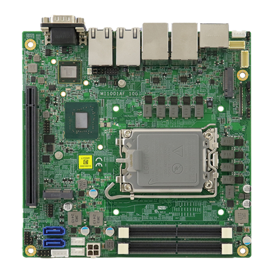
Page 15: Product View
General Information Product View Top View Bottom View MI1001 User Manual... -
Page 16: Board Dimensions
I/O View Board Dimensions MI1001 User Manual... -
Page 17: Chapter 2 Hardware Configuration
Chapter 2 Hardware Configuration This section provides information on jumper settings and connectors on the MI1001 and other installation information in order to set up a workable system. The topics covered are: • Essential installations before you begin • Jumper and connector locations •... -
Page 18: Essential Installations Before You Begin
Essential Installations Before You Begin Follow the instructions below to install the memory modules. 2.1.1 Installing the Memory To install the modules, locate the memory slot on the board and perform the following steps: Align the key of the memory module with that on the memory slot and insert the module slantwise. -
Page 19: Setting The Jumpers
Hardware Configuration Setting the Jumpers Set up and configure your MI1001 by using jumpers for various settings and features according to your needs and applications. Contact your supplier if you have doubts about the best configuration for your use. 2.2.1 How to Set Jumpers Jumpers are short-length conductors consisting of several metal pins with a non-conductive base mounted on the circuit board. -
Page 20: Jumper & Connector Locations
Jumper & Connector Locations MI1001 User Manual... -
Page 21: Jumpers Quick Reference
Hardware Configuration Jumpers Quick Reference Jumper Function LVDS Power Selection eDP Panel Power Selection LVDS Power Brightness Selection PCIe (x16) Bifurcation Selection Clear CMOS Data Clear RTC AT / ATX Selection Clear CMOS2 2.4.1 JP1: LVDS Power Selection Function Pin closed Illustration 3.3V (default) -
Page 22: Jp2: Edp Panel Power Selection
2.4.2 JP2: eDP Panel Power Selection Function Illustration 3.3V (default) MI1001 User Manual... -
Page 23: Jp3: Lvds Power Brightness Selection
Hardware Configuration 2.4.3 JP3: LVDS Power Brightness Selection Function Illustration 3.3V (default) MI1001 User Manual... -
Page 24: Jp4: Pci Express Bifurcation
2.4.4 JP4: PCI Express Bifurcation Function Pin closed Illustration 1 x PCIe (x16) (default) 2 x PCIe (x8) MI1001 User Manual... -
Page 25: Jp5: Clear Cmos
Hardware Configuration 2.4.5 JP5: Clear CMOS Function Pin closed Illustration Normal (default) Clear CMOS MI1001 User Manual... -
Page 26: Jp6: Clear Me Rtc
2.4.6 JP6: Clear ME RTC Function Pin closed Illustration Normal (default) Clear ME RTC MI1001 User Manual... -
Page 27: Jp9: At/Atx Select
Hardware Configuration 2.4.7 JP9: AT/ATX Select Function Pin closed Illustration (default) MI1001 User Manual... -
Page 28: J9: Clear Cmos2
2.4.8 J9: Clear CMOS2 Function Pin closed Illustration Clear CMOS Close MI1001 User Manual... -
Page 29: Connectors Quick Reference
Hardware Configuration Connectors Quick Reference Connector Function CN7 (top) COM1 RS-232/422/485 Port CN7 (bottom) COM2 RS-232 Port CN8, CN9 SATA Connectors eDP Connector J2, J4 LVDS Connector (1st/2nd channel) LCD Backlight Connector J6, J7 DDR5 UDIMM CHA/CHB USB 2.0 #5/#6 Connector 24V DC_IN Power Connector SATA HDD Power Connector M.2 E-Key Socket... -
Page 30: Cn7(Top): Com1 Rs-232/422/485 Ports
2.5.1 CN7(top): COM1 RS-232/422/485 Ports 2.5.2 CN7(bottom): COM2 RS-232 Port Signal Name RS-232 RS-422 RS-485 DATA- DATA+ Ground Ground Ground MI1001 User Manual... -
Page 31: Cn8, Cn9: Sata Connectors
Hardware Configuration 2.5.3 CN8, CN9: SATA Connectors Signal Name Ground Ground Ground MI1001 User Manual... -
Page 32: Cn1: Edp Connector
2.5.4 CN1: eDP Connector Signal Name Signal Name eDP VCC TXN0 eDP VCC TXP0 eDP VCC Ground eDP VCC AUXP eDP VCC AUXN Ground Ground +3.3V Ground +12V Ground Hot Plug detect Ground Ground TXN3 TXP3 Back Light Control Ground Back Lignt Enable TXN2 +12V... -
Page 33: J2, J4 Lvds Connector (1St Ch, 2Nd Ch)
Hardware Configuration 2.5.5 J2, J4 LVDS Connector (1st ch, 2nd ch) Signal Name Signal Name TX0P TX0N Ground Ground TX1P TX1N Ground Ground TX2P TX2N Ground Ground CLKP CLKN Ground Ground TX3P TX3N MI1001 User Manual... -
Page 34: J3: Lcd Backlight Connector
2.5.6 J3: LCD Backlight Connector Signal Name Signal Name +12V Brightness Control Backlight Enable Ground MI1001 User Manual... -
Page 35: J5: M.2 M-Key Nvme (Cpu)
Hardware Configuration 2.5.7 J5: M.2 M-Key NVME (CPU) 2.5.8 J6, J7: DDR5 UDIMM CHA/CHB MI1001 User Manual... -
Page 36: J8: Usb 2.0 #5/#6 Connector
2.5.9 J8: USB 2.0 #5/#6 Connector Signal Name Signal Name Ground Ground MI1001 User Manual... -
Page 37: J10: 24V Dc_In Power Connector
Hardware Configuration 2.5.10 J10: 24V DC_IN Power Connector Signal Name Signal Name Ground +24V Ground +24V MI1001 User Manual... -
Page 38: J12: Sata Hdd Power Connector
2.5.11 J12: SATA HDD Power Connector Signal Name Signal Name Ground Ground +12V MI1001 User Manual... -
Page 39: J13: M.2 E-Key Socket
Hardware Configuration 2.5.12 J13: M.2 E-Key Socket MI1001 User Manual... -
Page 40: J16: Front Panel Connector
2.5.13 J16: Front Panel Connector Signal Name Signal Name Power BTN Power BTN HDD LED+ HDD LED- Reset BTN Reset BTN Power LED+ Power LED- MI1001 User Manual... -
Page 41: J17: Digital I/O Connector (4 In, 4 Out)
Hardware Configuration 2.5.14 J17: Digital I/O Connector (4 in, 4 out) Signal Name Signal Name Ground Out3 Out1 Out2 Out0 MI1001 User Manual... -
Page 42: Cpu_Fan1: Cpu Fan Power Connector
2.5.15 CPU_FAN1: CPU Fan Power Connector Signal Name Ground +12V Rotation detection Control Note: PWM Only 2.5.16 SYS_FAN1: System Fan Power Connector Signal Name Ground +12V Rotation detection Control Note: PWM Only MI1001 User Manual... -
Page 43: Chapter 3 Drivers Installation
Chapter 3 Drivers Installation This chapter introduces installation of the following drivers: • ® Intel Chipset Software Installation Utility • VGA Driver • HD Audio Driver • ® Intel Trusted Execution Engine Drivers • ® Intel Serial I/O Drivers • LAN Drivers... -
Page 44: Introduction
Introduction This section describes the installation procedures for software and drivers. The software and drivers are included with the motherboard. If you find anything missing, please contact the distributor where you made the purchase. The contents of this section include the following: Note: After installing your Windows operating system, you must install the ®... - Page 45 Driver Installation ® When the Welcome screen to the Intel Chipset Device Software appears, click Next to continue. Accept the terms in the License Agreement and click Accept. MI1001 User Manual...
- Page 46 On the Readme File Information screen, click Install. When the driver has been completely installed, press Finish to complete the setup process. MI1001 User Manual...
-
Page 47: Vga Driver Installation
Driver Installation VGA Driver Installation Click Intel on the left pane and then Intel(R) AlderLake-S/ RaptorLake-S Chipset Drivers, and Intel(R) HD Graphics Driver on the right pane. When the Intel Graphics Driver Installer screen appears, click Begin installation. MI1001 User Manual... - Page 48 Click I agree to accept the INTEL SOFTWARE LICENSE AGREEEMENT. In the Pre-Install stage, press Start to start installing the new graphics driver. The next screen will indicate that the new graphics driver is being installed. When the message “Installation complete!” appears, restart your system in order to apply the driver changes.
-
Page 49: Realtek Hd Audio Driver Installation
Driver Installation Realtek HD Audio Driver Installation Click Intel on the left pane and then Intel(R) AlderLake-S/ RaptorLake-S Chipset Drivers, and Realtek High Definition Audio Driver on the right pane. On the Welcome screen of the InstallShield Wizard, click Next to install the drivers. -
Page 50: Lan Drivers Installation
LAN Drivers Installation Click LAN Card on the left pane and then Intel PRO LAN Network Drivers on the right pane. Click Install Drivers and Software. MI1001 User Manual... - Page 51 Driver Installation When the Welcome to the install wizard for Intel(R) Nework Connection screen appears, press Next. On the Setup Options screen, select the program features you want installed. Then press Next to continue. On the Ready to Install the Program screen, press Install to begin the installation.
-
Page 52: Intel ® Me Drivers Installation
® Intel ME Drivers Installation Click Intel on the left pane and then Intel(R) AlderLake-S/ RaptorLake-S Chipset Drivers, and Intel(R) ME Drivers on the right pane. When the Welcome screen to the Intel® Management Engine Components appears, press Next. Accept the terms in the License Agreement and press Next. On the next screen, press Next to install to the default folder. -
Page 53: Intel ® Serial Io Drivers Installation
Driver Installation ® Intel Serial IO Drivers Installation Click Intel on the left pane and then Intel(R) AlderLake-S/ RaptorLake-S Chipset Drivers, and Intel(R) Serial IO Drivers on the right pane. When the Welcome screen to the Intel® Serial IO appears, click Next. Accept the terms in the license agreement and press Next. - Page 54 This page is intentionally left blank. MI1001 User Manual...
-
Page 55: Chapter 4 Bios Setup
Chapter 4 BIOS Setup This chapter describes the different settings available in the AMI BIOS that comes with the board. The topics covered in this chapter are as follows: • Main Settings • Advanced Settings • Chipset Settings • Security Settings •... -
Page 56: Introduction
4.1 Introduction The BIOS (Basic Input/Output System) installed in the ROM of your ® computer system supports Intel processors. The BIOS provides critical low-level support for standard devices such as disk drives, serial ports and parallel ports. It also provides password protection as well as special support for detailed fine-tuning of the chipset controlling the entire system. -
Page 57: Main Settings
BIOS Setup 4.3 Main Settings BIOS Setting Description System Language Choose the system default language. Sets the date. Use the <Tab> key to switch System Date between the date elements. Set the time. Use the <Tab> key to switch System Time between the time elements. -
Page 58: Connectivity Configuration
4.4.1 Connectivity Configuration BIOS Setting Description This is an option to enable/disable BT audio offload which enables audio input from BT BT Audio Offload device to the audio DSP and enables power efficient audio output to BT device. This is an option intended to enable/disable DDR-RFIM feature for Connectivity. -
Page 59: Cpu Configuration
BIOS Setup 4.4.2 CPU Configuration BIOS Setting Description Intel (VMX) Virtualization When enable, a VMM can utilize the Technology additional hardware capabilities provided by Vanderpool Technology. Active Performance-cores Number of P-cores to enable in each processor package. Note: Number of Active Efficient-cores Cores and E-cores are looked at together. -
Page 60: Power & Performance
4.4.3 Power & Performance BIOS Setting Description Intel(R) Allows more than two frequency ranges to be SpeedStep(tm) supported. Enable/Disable Intel(R) Speed Shift Intel(R) Speed Shift Technology support. Enabling will expose the Technology CPPC v2 interface to allow for hardware controlled P-states. Enable/Disable processor Turbo Mode Turbo Mode (requires EMTTM enabled too). -
Page 61: Pch-Fw Configuration
BIOS Setup 4.4.4 PCH-FW Configuration BIOS Setting Description When Disabled ME will be put into ME ME State Temporarily Disabled Mode. Enable/Disable Intel(R) Manageability features. Manageability Note: This option disables/enables Features State Manageability Features support in FW. To disable support platform must be in an unprovisioned state first. -
Page 62: Trusted Computing
4.4.5 Trusted Computing BIOS Setting Description Enables / Disables BIOS support for security device. OS will not show security device. Security Device Support TCG EFI protocol and INTIA interface will not be available. SHA256 / SHA384 / Option: Enabled / Disabled SH3_256 PCR Bank Schedule an operation for the security device. -
Page 63: Acpi Settings
BIOS Setup 4.4.6 ACPI Settings BIOS Setting Description Enable ACPI Auto Enables or Disables BIOS ACPI Auto Configuration Configuration Enables / Disables the system ability to hibernate (OS/S4 Sleep State). This option may Enable Hibernation be not effective with some OS. Select the highest ACPI sleep state the system will enter when the Suspend button is pressed. - Page 64 4.4.7 LVDS (eDP/DP) Configuration BIOS Setting Description LVDS (eDP/DP) Support LVDS (eDP/DP) ON/OFF Panel Color Depth Options: 18 BIT, 24bit(VESA), 24bit(JEIDA) LVDS Channel Type Options: Single, Dual Panel Type Options: 800 x 480, 800 x 600, 1024 x 768, 1280 x 768, 1280 x 800, 1280 x 960, 1366 x 768, 1440 x 900, 1600 x 900, 1600 x 1200, 1680 x 1050, 1920 x 1080, 1920 x 1200 LVDS Brightness Level...
- Page 65 BIOS Setup 4.4.8 F8196x Super IO Configuration MI1001 User Manual...
- Page 66 4.4.9 F8196x Super IO Hardware Monitor BIOS Setting Description Enables / Disables the CPU smart fan feature. CPU Smart Fan Control Options: Disabled / 50 °C / 60 °C / 70 °C / 80 °C Enables / Disables the system smart fan SYS Smart Fan feature.
-
Page 67: Usb Configuration
BIOS Setup 4.4.10 USB Configuration BIOS Setting Description • Enabled enables Legacy USB support. • Auto disables legacy support if there is no Legacy USB Support USB device connected. • Disabled keeps USB devices available only for EFI applications. This is a workaround for OSes without XHCI XHCI Hand-off hand-off support. -
Page 68: Network Stack Configuration
4.4.11 Network Stack Configuration BIOS Setting Description Network Stack Enables / Disables UEFI Network Stack. Enables / Disables IPv4 PXE Boot Support. IPv4 PXE Support If disabled, Ipv4 PXE boot option will not be created. Enables / Disables IPv4 HTTP Boot Support. IPv4 HTTP Support If disabled, Ipv4 HTTP boot option will not be created. - Page 69 BIOS Setup 4.4.12 NVMe Configuration MI1001 User Manual...
- Page 70 4.4.13 Intel(R) Ethernet Converged Network Adapter MI1001 User Manual...
-
Page 71: Chipset Settings
BIOS Setup 4.5 Chipset Settings BIOS Setting Description System Agent (SA) System Agent (SA) parameters Configuration PCH-IO PCH parameters Configuration 4.5.1 System Agent (SA) Configuration Graphics Configuration BIOS Setting Description Select which of IGFX/PEG/PCI Graphics device should be primary display or select HG Primary Display for Hybrid Gfx. - Page 72 Sets the aperture size. Note: Above 4 GB MMIO BIOS assignment is Aperture Size automatically enabled when selecting 2048 MB aperture. To use this feature, disable CSM support. VMD Setup Menu MI1001 User Manual...
- Page 73 BIOS Setup 4.5.2 PCH-IO Configuration BIOS Setting Description SATA Configuration SATA device options settings. Power Failure Specify what state to go to when power is re- applied after a power failure (G3 state). Options: Always On, Always Off MI1001 User Manual...
- Page 74 BIOS Setting Description SATA Controller(s) Enables / Disables the SATA device. SATA Mode Determines how SATA controller(s) operate. Selection Serial ATA Ports Enables / Disables SATA ports. Hot Plug Designates the port as Hot Pluggable. MI1001 User Manual...
-
Page 75: Security Settings
BIOS Setup 4.6 Security Settings BIOS Setting Description Administrator Sets an administrator password for the setup Password utility. User Password Sets a user password. Secure Boot Configures Secure Boot. 4.6.1 Secure Boot MI1001 User Manual... - Page 76 BIOS Setting Description Secure Boot feature is Active if Secure Boot is enabled. Platform Key (PK) Is enrolled and the Secure Boot system is in User mode. The mode change requires platform reset. Secure Boot mode options: Standard or Custom. Secure Boot Mode In Custom mode, Secure Boot policy variables can be configured by a physically present user...
-
Page 77: Boot Settings
BIOS Setup 4.7 Boot Settings BIOS Setting Description Number of seconds to wait for setup activation Setup Prompt key. Timeout 65535(0xFFFF) means indefinite waiting. Bootup NumLock Selects the keyboard NumLock state. State Quiet Boot Enables / Disables Quiet Boot option. Enables or disables boot with initialization of a minimal set of devices required to launch Fast Boot... -
Page 78: Save & Exit Settings
4.8 Save & Exit Settings BIOS Setting Description Save Changes and Exits system setup after saving the changes. Exit Discard Changes Exits system setup without saving any and Exit changes. Save Changes and Resets the system after saving the changes. Reset Discard Changes Resets system setup without saving any... -
Page 79: Mebx
BIOS Setup 4.9 MEBx MI1001 User Manual... - Page 80 This page is intentionally left blank. MI1001 User Manual...
-
Page 81: Appendix
Appendix This section provides the mapping addresses of peripheral devices and the sample code of watchdog timer configuration. -
Page 82: I/O Port Address Map
I/O Port Address Map Each peripheral device in the system is assigned a set of I/O port addresses which also becomes the identity of the device. The following table lists the I/O port addresses used. Address Device Description 0x00000A00-0x00000A0F Motherboard resources 0x00000A10-0x00000A1F Motherboard resources 0x00000A20-0x00000A2F... - Page 83 Appendix Address Device Description 0x00000020-0x00000021 Programmable interrupt controller 0x00000024-0x00000025 Programmable interrupt controller 0x00000028-0x00000029 Programmable interrupt controller 0x0000002C-0x0000002D Programmable interrupt controller 0x00000030-0x00000031 Programmable interrupt controller 0x00000034-0x00000035 Programmable interrupt controller 0x00000038-0x00000039 Programmable interrupt controller 0x0000003C-0x0000003D Programmable interrupt controller 0x000000A0-0x000000A1 Programmable interrupt controller 0x000000A4-0x000000A5 Programmable interrupt controller 0x000000A8-0x000000A9...
-
Page 84: Interrupt Request Lines (Irq)
Interrupt Request Lines (IRQ) The following table shows the IRQ used by the devices on board. Level Function IRQ 4294967264~88 Intel(R) Ethernet Controller I226-V #3 Intel(R) USB 3.20 eXtensible Host Controller IRQ 4294967289 - 1.20 (Microsoft) IRQ 0 System timer IRQ 4294967238 Intel(R) Management Engine Interface #1 IRQ 4294967292... -
Page 85: Watchdog Timer Configuration
Appendix Watchdog Timer Configuration The Watchdog Timer (WDT) is used to generate a variety of output signals after a user programmable count. The WDT is suitable for use in the prevention of system lock-up, such as when software becomes trapped in a deadlock. - Page 86 bTime = strtol (argv[1], endptr, 10); printf("System will reset after %d seconds\n", bTime); if (bTime) EnableWDT(bTime); } else DisableWDT(); } return 0; //--------------------------------------------------------------------------- void EnableWDT(int interval) unsigned char bBuf; bBuf = Get_F81966_Reg(0x2B); bBuf &= (~0x20); Set_F81966_Reg(0x2B, bBuf); //Enable WDTO Set_F81966_LD(0x07); //switch to logic device 7 Set_F81966_Reg(0x30, 0x01);...
- Page 87 Appendix // THIS CODE AND INFORMATION IS PROVIDED "AS IS" WITHOUT WARRANTY OF ANY // KIND, EITHER EXPRESSED OR IMPLIED, INCLUDING BUT NOT LIMITED TO THE // IMPLIED WARRANTIES OF MERCHANTABILITY AND/OR FITNESS FOR A PARTICULAR // PURPOSE. //--------------------------------------------------------------------------- #include "F81966.H" #include <dos.h>...
- Page 88 //--------------------------------------------------------------------------- void Set_F81966_Reg( unsigned char REG, unsigned char DATA) Unlock_F81966(); outportb(F81966_INDEX_PORT, REG); outportb(F81966_DATA_PORT, DATA); Lock_F81966(); //--------------------------------------------------------------------------- unsigned char Get_F81966_Reg(unsigned char REG) unsigned char Result; Unlock_F81966(); outportb(F81966_INDEX_PORT, REG); Result = inportb(F81966_DATA_PORT); Lock_F81966(); return Result; //--------------------------------------------------------------------------- //--------------------------------------------------------------------------- // THIS CODE AND INFORMATION IS PROVIDED "AS IS" WITHOUT WARRANTY OF ANY // KIND, EITHER EXPRESSED OR IMPLIED, INCLUDING BUT NOT LIMITED TO THE // IMPLIED WARRANTIES OF MERCHANTABILITY AND/OR FITNESS FOR A PARTICULAR // PURPOSE.
-
Page 89: Onboard Connector Types
Appendix Onboard Connector Types Compatible Function Connector Type Mating Type (for reference) YIMTEX COM1 & COM2 D-SUB 9-pin 40909AANSABR RS-232/422/485 Digital I/O E-CALL Dupont Connector 0196-01-200-100 2.0 mm 2*5-pin E-CALL Dupont USB 2.0 0126-01-2811009 2.54 mm 2*5-pin Dupont Front Panel E-CALL 2.54 mm 2*5- Settings... -
Page 90: Mi1001 Usb Power Control Bit Mapping
MI1001 USB Power Control Bit Mapping. Function Connector Software Mapping M.2 –E Key bit_0 USB 3.1 bit_1 MI1001 User Manual...
Need help?
Do you have a question about the MI1001 Series and is the answer not in the manual?
Questions and answers