Table of Contents
Advertisement
Quick Links
1.
GENERAL INTRODUCTION ................................................... 1
1.1. Document Purpose ............................................................... 1
1.2. Product Purpose ................................................................... 1
1.3. Product Mounting and Location ............................................ 1
2.
PRODUCT DESCRIPTION ....................................................... 2
3.
INSTALLATION ........................................................................ 4
3.1. Inspecting the Product .......................................................... 4
3.2. Following and Using Safety Precautions................................ 4
3.3. Obtaining Tools and Equipment ............................................ 4
3.4. Preparing the Installation Site ............................................... 4
3.5. Lifting the CUBE .................................................................. 5
3.6. Mounting the CUBE ............................................................. 5
3.7. CUBE Wiring and Equipment................................................ 7
3.8. Conduit Seals ..................................................................... 10
3.9. Verifying the Installation ..................................................... 10
4.
PERIODIC MAINTENANCE .................................................. 10
5.
TECHNICAL ASSISTANCE AND REPAIR SERVICE .......... 11
6.
WARRANTY & CUSTOMER SERVICE ................................. 11
7.
SPECIFICATIONS ................................................................... 11
7.1. Regulatory Specifications .................................................... 11
7.2. Product Specifications ........................................................ 12
7.3. Macro Alarm Wiring........................................................... 13
1. GENERAL INTRODUCTION
1.1. Document Purpose
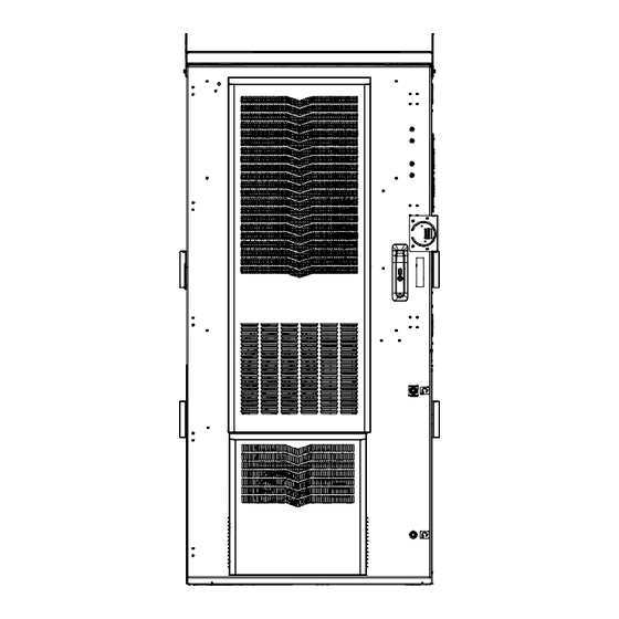
This document provides general information for the CUBE-SS4C2288V2 of the Charles Industries' Universal Broadband Enclosure
(CUBE) product line. Figure 1 shows a closed front view of the enclosure.
Hereafter, the Charles Universal Broadband Enclosure CUBE-SS4C2288V2 will be referred to as the "CUBE."
1.2. Product Purpose
The CUBE consists of a protective enclosure for an integrated system of electronic components and equipment that can serve fiber and
copper interfaces.
1.3. Product Mounting and Location
This enclosure is suitable for outside plant-type (OSP) locations and those that may require NEC compliance. The outdoor, weather-
resistant CUBE is to be mounted on a concrete pad or steel grate platform. The installer connects the power, fiber and copper connections.
Detailed mounting and installation information is covered in Section 3.
©Copyright 2024 Charles Industries LLC. All rights reserved.
Availability of features and technical specifications herein are subject to change without notice.
Charles is a registered trademark of Charles Industries.
Charles Universal Broadband Enclosure
CUBE-SS4C2288V2
General Description and Installation
Figure 1
-NOTE-
LT-SS4C2288V2
7
th
Printing, April 15, 2024
Front View of the CUBE
Page 1 of 13
Advertisement
Table of Contents

Subscribe to Our Youtube Channel
Related Manuals for Amphenol Charles CUBE-SS4C2288V2


Summary of Contents for Amphenol Charles CUBE-SS4C2288V2
-
Page 1: Table Of Contents
LT-SS4C2288V2 Printing, April 15, 2024 Charles Universal Broadband Enclosure CUBE-SS4C2288V2 General Description and Installation GENERAL INTRODUCTION ........... 1 1.1. Document Purpose ............... 1 1.2. Product Purpose ..............1 1.3. Product Mounting and Location ..........1 PRODUCT DESCRIPTION ............2 INSTALLATION ................ 4 3.1. -
Page 2: Product Description
LT-SS4C2288V2 2. PRODUCT DESCRIPTION The CUBE has equipment and battery compartments. The equipment compartment includes 22RU of 23” horizontal rack mount space and 2RU of 19” vertical rack mount space, with a 12k BTU HVAC system mounted on the door. The battery compartment supports three strings of customer supplied 210Ah VRLA batteries and has a 2k BTU HVAC system on the door. - Page 3 LT-SS4C2288V2 (4) LIFTING HOISTS SOLAR SHIELD DOOR ALARM AND HVAC CUTOFF SWITCHES ALARM TERMINAL EQUIPMENT COMPARTMENT PANEL (2) 2X8 POSITION GROUND BARS 3PT LATCH 216 STYLE PADLOCKABLE DOOR HANDLE BATTERY COMPARTMENT GFCI OUTLET WIND LATCH OVERHEAT THERMOSTAT 22RU, 23” (2) BATTERY HORIZONTAL RETAINER BRACKETS RACK SPACING...
-
Page 4: Installation
LT-SS4C2288V2 3. INSTALLATION 3.1. Inspecting the Product The CUBE is shipped mounted upright on a skid. Remove the bolts, unpack the unit, and dispose of the packaging material. -INSPECTION NOTE- Visually inspect the unit for damages prior to installation. If the equipment was damaged in transit, immediately report the extent of the damage to the transportation company. -
Page 5: Lifting The Cube
LT-SS4C2288V2 3.5. Lifting the CUBE See Table 1 for CUBE weight. Charles recommends the following procedure for lifting the CUBE. SPREADER BARS 3.5.1. Required Equipment SHORT SLINGS/CHAINS • One derrick (crane) capable of lifting the CUBE Spreader bars • • Four lifting slings or chains with each having a 2,500 lbs. - Page 6 LT-SS4C2288V2 3.6.2. Constructing a New Pad Use only concrete for new pad construction. Do not use substitute materials • since they lack the rigidity for CUBE placement. 8.59 16.94 • Observe local building practices for pad construction. Charles recommends that 3.45 the pad should extend a minimum of 8”...
-
Page 7: Cube Wiring And Equipment
LT-SS4C2288V2 3.7. CUBE Wiring and Equipment After the CUBE is properly mounted in the desired location, apply No-Ox where bus bar and other 2-hole lug connections will be made. Install ground and power connections. Always ground the equipment first, before making any other connections. WARNING Perform all bonding and grounding connections prior to any electrical and communications connections. -
Page 8: Ground Connection
LT-SS4C2288V2 3.7.1. Ground Connection Use the two 2x8 position ground bars provided in the equipment compartment for all NUTS BELLEVILLE WASHERS grounding of internal equipment. Stack hardware as shown in Figure 8. External ground lugs FLAT WASHERS are available on the rear of the battery compartment for connecting a site ground wire. GROUNDING LUG 3.7.2. -
Page 9: Hvac Operation
LT-SS4C2288V2 See Figure 9 for a diagram of the in-series wiring. Figure 9 Alarm Connections In Series • 3.7.3. Battery Jumpers The equipment compartment has a set of DIN rail terminal blocks with jumpers that serve as a battery breaker monitor. The default jumper positions are on the outside and assume that all battery strings are present and breakers are turned on. -
Page 10: Conduit Seals
LT-SS4C2288V2 3.7.6. Macro Alarm Terminal Panel An integrated macro-site alarm panel is mounted on the left wall of the cabinet. This panel provides forty protected dry contact alarm inputs to screw down terminals or 66-block connections (Figure 10). The cabinet comes with a standard alarm schedule label (See Table 2). The table can be replaced or augmented to match the specific alarms being used. -
Page 11: Technical Assistance And Repair Service
LT-SS4C2288V2 5. TECHNICAL ASSISTANCE AND REPAIR SERVICE For questions on product repair or if technical assistance is required, contact Charles Technical Support. 847-806-8500 techserv@charlesindustries.com (email) http://www.charlesindustries.com/techserv.htm 6. WARRANTY & CUSTOMER SERVICE Charles Industries LLC offers a one-year warranty on the CUBE product. The Charles warranty is limited to the operation of the CUBE hardware as described in this documentation and does not cover equipment which may be integrated by a third party. -
Page 12: Product Specifications
LT-SS4C2288V2 7.2. Product Specifications Physical Dimensions 74”Hx34”Wx32”D Weight Approx. 620 lbs. as shipped 23” Equipment Rack Space and Hole Spacing 38.5” (22RU) rack spacing with tapped EIA #12-24 mounting holes Battery Tray Size 12”Hx30”Wx23”D Materials 0.125” aluminum Maximum Supported Weight Rack Rails: 308 lbs. -
Page 13: Macro Alarm Wiring
LT-SS4C2288V2 7.3. Macro Alarm Wiring Alarm Number Description Door Intrusion Commercial Power Failure Surge Suppressor/Lightening Arrestor Rectifier Failure Multiple Rectifier Failure Battery Discharge Low Voltage DC Power Failure Generator Running CC10 Generator Low Fuel CC11 Generator Failure CC12 HVAC Failure CC13 High Temp CC14...
Need help?
Do you have a question about the Charles CUBE-SS4C2288V2 and is the answer not in the manual?
Questions and answers