Table of Contents
Advertisement
Quick Links
Advertisement
Chapters
Table of Contents

Related Manuals for Komet EnGO-Motor


Summary of Contents for Komet EnGO-Motor
- Page 2 ® ® ® ® ® ® ® ® ® ® ® ® Brasseler , Komet , Art2 , CeraBur , CeraCut , CeraDrill , CeraFusion , CeraPost , DC1 , DCTherm , Derminator , FastFile , F360 , F6 ®...
-
Page 3: Table Of Contents
EnGO - Product Introduction 1 Product introduction ································································ 1 2 Installation ················································································ 2 3 Function and operation of product ·········································· 5 4 Operation instruction································································ 7 5 Troubleshooting ······································································ 13 6 Cleaning, Disinfection and Sterilization ································· 13 7 Storage, maintenance and transport ····································· 17 8 Environmental protection ·······················································... -
Page 4: Product Introduction
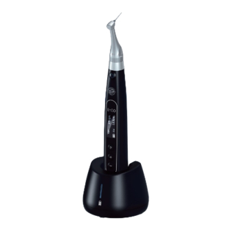
360 degress rotation of the contra angle. d) Make use of real-time feedback technology and dynamic torque control, to effectively prevent inadvertent file separation. 1.2 Model and specification Model: Ai-Motor(EnGo-Motor) Please refer to packing list for device configurations. 1.3 Components The device is composed of charging base, motor handpiece, contra angle, measuring wire, lip hook, file clip, power adapter, protective silicon cover, etc. -
Page 5: Installation
EnGO - Product Introduction 1.9.5 Degree of protection during use in the presence of flammable mixtures of anaesthetics with air, oxygen or nitrous oxide: The device must not be used in the presence of flammable mixtures of anaesthetics with air, oxygen or nitrous oxide. 1.9.6 Active parts: contra angle, lip hook, file clip, touch probe. - Page 6 EnGO - Product Introduction This mode is for canal measurement. The motor handpiece does not run in this mode. 2.2.1.2 CW Mode The motor handpiece rotates forward 360°, clockwise direction. 2.2.1.3 CCW Mode The motor handpiece rotates in a counterclockwise direction only. This mode is used to inject calcium hydroxide or other medicaments.
- Page 7 EnGO - Product Introduction file progression towards the apex. The digital numbers -1 and -2 indicate that the file has passed the apex foramen. The digital number “00” indicates that the file has reached the apex foramen. Subtract 0.5 -1 mm from the measured file length to calculate the working length. These numbers are used to estimate the canal’s working length. 2.3 Instructions for contra angle 2.3.1 The contra angle uses precision gear transmission, and the transmission ratio is 6:1.
-
Page 8: Function And Operation Of Product
EnGO - Product Introduction Before plugging in and pulling out the file, the motor handpiece must be stopped. Be careful when removing files to avoid injury to fingers. Removing files without holding down the push button will damage the chuck of contra angle. 2.6 Connection of the canal measurement equipment This is not required if the canal measurement function will not be used. -
Page 9: Screen Display
EnGO - Product Introduction With the motor handpiece turned off, hold down the setting button “P” and press main button to enter handpiece functions setting, press setting button “P” until the required target setting has been reached, press adjusting button “+”/“-” to adjust, then press main button to confirm. 3.2 Screen display Standby interface a) Customized program sequence number 0 - 9, totally 10 programs in total. -
Page 10: Operation Instruction
EnGO - Product Introduction Speed File rotation speed. Torque For CW and CCW modes, the torque value (Torque Limit) that triggers reverse rotation. For ATR mode, the torque (Torque Limit/Trigger Torque) value (Trigger Torque) that triggers ATR action. 4 Operation instruction 4.1 Power on and power off 4.1.1 Starting and stopping of motor handpiece a) While the handpiece is set to "Power off", press the main button and the handpiece will switch to standby mode. - Page 11 EnGO - Product Introduction Actions that happen automatically when the file tip reaches the predetermined apical reference point inside the canal (flash bar position). Benefit from integration of length determination: when the file reaches the reference point, the motor will response according to setting, i.e.
- Page 12 EnGO - Product Introduction For convenience, we preset some common file systems. Press adjusting button “+”/“-” to switch to preset program (M0-M9, preset program 1 - 5 ), the interface will be displayed as shown on the left. Keep the setting button “P” pressed for a longer period of time “P” to enter preset program during standby mode, the interface will be displayed as shown on the left.
-
Page 13: Motor Operation
EnGO - Product Introduction Cautions: 1. Protective function of automatic reverse is ONLY suitable for CW mode. 2. This function is forbidden under CCW mode, ATR mode. 3. When the motor handpiece battery indicator indicates a low battery capacity, the low battery capacity is insufficient to support the motor handpiece enough to reach the limit torque value, that is, the auto-reverse function will not work properly. - Page 14 EnGO - Product Introduction 11 When the device is used as an apex locator only, we suggest that you put the motor handpiece on the charging base to get a better visual angle. Press setting button “P” once during standby state, press adjusting button “+”/“-” to select EAL operation mode, then press main button to confirm.
-
Page 15: Battery Charging
When the blue indicator on the charging base flashes, it is charging. When the motor handpiece is fully charged, the blue indicator on the charging base remains permanently lit without flashing (Only for EnGO-Motor). After charging, please unplug the power adapter. -
Page 16: Troubleshooting
EnGO - Product Introduction 13 Only the original oil injection nozzle can be used for oiling of contra angle. The contra angle needs to be lubricated after cleaning and disinfection, but before sterilization. 1. Firstly, screw the injecting nozzle onto the jet of oil bottle. (Around 1 to 3 turns) 2. - Page 17 EnGO - Product Introduction 4. Repeat the above steps at least 3 times. Note: a) Use distilled water or deionized water at room temperature for cleaning. 6.3.1.2 Manual disinfection steps: 1. Soak the dry soft cloth with 75% alcohol. 2. Wipe all surfaces of headpiece, charger, base and other components with a wet soft cloth for at least 3 minutes. 3.
- Page 18 EnGO - Product Introduction 15 a) Press the push-button and pull out the shank/file. b) When removing the protective silicon cover, pull it straight out slowly. c) When inserting and removing the contra-angle, turn the handpiece power off beforehand. 6.4.3 Cleaning The cleaning should be performed no later than 24 hours after the operation.
- Page 19 EnGO - Product Introduction Methods: 1. Spread a clean white sheet of paper (white cloth) on the flat table, point the product against the white paper (white cloth), and then dry the product with filtered dry compressed air (maximum pressure 3 bar). The drying cycle is completed when no further liquid is sprayed onto the white paper (white cloth).
-
Page 20: Storage, Maintenance And Transport
EnGO - Product Introduction 17 6.4.10 Transport 1. Prevent excessive shock and vibration during transport, and handle with care; 2. The products should not be mixed with dangerous goods during transport. 3. Avoid exposure to sun or rain or snow during transport. 7 Storage, maintenance and transport 7.1 Storage 7.1.1 This equipment should be stored in a room where the relative humidity is 10 % ~ 93 %, atmospheric pressure is 70kPa to106kPa, and the... -
Page 21: Statement
Table 1: Declaration - electromagnetic emissions Guidance and manufacturer’s declaration - electromagnetic emissions The model EnGO-Motor is intended for use in the electromagnetic environment specified below. The customer or the user of the model EnGO-Motor should assure that it is used in such an environment. - Page 22 RF transmitters, an electromagnetic site survey should be considered. If the measured field strength in the location in which the model EnGO- Motor is used exceeds the applicable RF compliance level above, the model EnGO-Motor should be observed to verify normal operation. If abnormal performance is observed, additional measures may be necessary, such as reorienting or relocating the model EnGO-Motor.
- Page 23 EnGO - Product Introduction Brasseler®, Komet®, Art2®, CeraBur®, CeraCut®, CeraDrill®, CeraPost®, DC1®, DIAO®, FastFile®, F360®, F6 SkyTaper®, H4MC®, KometBioSeal®, OccluShaper®, OptiPost®, PolyBur®, PrepMarker®, Procodile®, Procodile Q® und SHAX® sind eingetragene Marken der Gebr. Brasseler GmbH & Co. KG. ReFlex® und EndoPilot® sind eingetragene Marken der Schlumbohm GmbH & Co. KG Die im Text genannten Produkte und Bezeichnungen sind zum Teil marken-, patent- und urheberrechtlich geschützt.
- Page 24 EnGO - Product Introduction 1 Produktvorstellung ································································· 22 2 Installation ·············································································· 23 3 Funktion und Bedienung des Produkts ································· 26 4 Betriebsanleitung ··································································· 28 5 Fehlersuche ············································································ 34 6 Reinigung, Desinfektion und Sterilisation ····························· 34 Lagerung, Wartung und Transport ············································ 38 8 Schutz der Umwelt ·································································...
-
Page 25: Produktvorstellung
Der EnGO-Motor ist ein kabelloses motorisiertes Handstück für endodontische Behandlungen mit einer integrierten Wurzelkanal- Messfunktion. Es kann für die Aufbereitung und Erweiterung von Wurzelkanälen verwen - det werden. Der EnGO-Motor ist in der Lage die Position der Feilenspitze im Kanal während der Erweiterung des Kanals darzustellen. -
Page 26: Installation
EnGO - Product Introduction 23 1.8.1 Art der Betriebsart: Kontinuierlich arbeitendes Gerät 1.8.2 Art des Schutzes gegen elektrischen Schlag: Gerät der Klasse II mit interner elektrischer Versorgung 1.8.3 Grad des Schutzes gegen elektrischen Schlag: Aktiver Teil Typ B 1.8.4 Schutzgrad gegen schädliches Eindrin - gen von Wasser: Gewöhnliches Gerät (IPX0) 1.8.5 Schutzgrad bei Verwendung in Gegen - wart von entflammbaren Gemischen von Anästhetika mit Luft, Sauerstoff oder Distickstoffoxid: Das Gerät darf nicht in Gegenwart von entflammbaren Gemischen von Anästhetika mit Luft, Sauerstoff oder Distickstoffmonoxid verwendet werden. - Page 27 EnGO - Product Introduction 2.2.1 Anzeigebildschirme für 6 Betriebsmodi und Standby 2.2.1.1 EAL-Modus Dieser Modus ist für die Längenmes - sung vorgesehen. Das Motorhandstück läuft in diesem Modus nicht. 2.2.1.2 CW-Modus Das Motorhandstück dreht sich um 360º im Uhrzeigersinn. 2.2.1.3 CCW-Modus Das Motorhandstück dreht sich nur im Gegenuhrzeigersinn.
- Page 28 EnGO - Product Introduction 25 Die Zählernummern 1.0, 2.0, 3.0 und die Ziffern 00 - 16 stellen nicht die tat - sächliche Länge vom apikalen Fora - men dar. Sie zeigen lediglich den Ver - lauf der Feile in Richtung Apex an. Die Digitalzahlen -1 und -2 zeigen an, dass die Feile das apikale Foramen passiert hat. Die Digitalzahl "00"...
-
Page 29: Funktion Und Bedienung Des Produkts
EnGO - Product Introduction 2.5.2 Entnahme der Feile Drücken Sie die Druckabdeckung nach unten und ziehen Sie die Feile direkt heraus. Warnhinweise: Vor dem Einstecken und Herausziehen der Feile muss das Motorhandstück angehalten werden. Seien Sie beim Entfernen von Feilen vorsichtig, um Verletzungen der Finger zu vermeiden. - Page 30 EnGO - Product Introduction 27 c) Individuelles Programm ändern Drücken Sie die Einstelltaste "+"/"-" im Standby-Zustand. d) Parametereinstellung Einstellknopf "P" drücken, um die gewünschten Zielparameter zu wählen. Drücken Sie die Taste "+"/"-" zum ändern, dann die Haupt-Taste oder warten Sie 5 Sekunden zur Bestätigung. e) Voreingestellte Programmwahl Drücken Sie die Einstelltaste "P"...
-
Page 31: Betriebsanleitung
EnGO - Product Introduction Apikale Aktion Die Aktion der Feile, wenn die Feilenspitze den Flash Bar Punkt erreicht. Position der Blitzleiste Zeigt den Punkt innerhalb des Kanals an, an dem die angegebene apikale Aktion ausgelöst wird. Automatischer Start Die Feilendrehung beginnt automatisch, wenn die Feile in den Kanal eingeführt wird. Automatisch stoppen Die Feilenrotation stoppt automatisch, wenn die Feile aus dem Kanal genommen wird. - Page 32 EnGO - Product Introduction 29 Die Drehmomenteinstellung kann von 0,4 Ncm bis 5,0 Ncm eingestellt werden. Drücken Sie den Einstellknopf "+"/"-", um das Drehmoment zu erhöhen oder zu verringern. Halten Sie die Taste über einen längeren Zeitraum gedrückt, um das Drehmoment schnell zu erhöhen oder zu verringern. Im ATR- Modus ist das Auslösedrehmoment von 0,4 Ncm ~ 4,0 Ncm verfügbar.
- Page 33 EnGO - Product Introduction Der Einfachheit halber sind einige gängige Feilensys - teme voreingestellt. Drücken Sie die Einstelltaste "+"/"- ", um zu den voreingestellten Programmen (M0- M9, voreingestelltes Programm 1 - 5) zu wechseln. Das Display wird wie links abgebildet angezeigt. Halten Sie die Einstelltaste "P"...
- Page 34 EnGO - Product Introduction 31 Vorsichtsmaßnahmen: 1. Die Schutzfunktion des automatischen Rücklaufs ist NUR für den CW-Modus geeignet. 2. Diese Funktion ist im CCW-Modus und im ATR-Modus nicht zulässig. 3. Wenn die Batterieanzeige des Motorhandstücks eine niedrige Batteriekapazität anzeigt, reicht die niedrige Batteriekapazität nicht aus, um das Motorhandstück ausreichend zu unterstützen, um den Grenzdrehmomentwert zu erreichen, d.h.
- Page 35 EnGO - Product Introduction Wenn das Gerät nur als Apex-Locator verwendet wird, empfehlen wir Ihnen, das Handstück auf die Ladestation zu legen, um einen besseren Sichtwinkel zu erhalten. Drücken Sie die Einstelltaste "P" einmal im Standby-Modus, drücken Sie die Einstelltaste "+"/"-", um den EAL-Betriebsmodus zu wählen, und drücken Sie dann die Haupttaste zur Bestä...
-
Page 36: Aufladen Der Batterie
Wenn die blaue Anzeige auf der Lade - station blinkt, wird aufgeladen. Wenn das Handstück vollständig aufgeladen ist, leuchtet die blaue Anzeige an der Ladestation dauerhaft, ohne zu blinken (nur für EnGO-Motor). Nach dem Aufla - den ziehen Sie bitte den Netzadapter aus der Steckdose. -
Page 37: Fehlersuche
EnGO - Product Introduction Zum Ölen des Winkelstücks darf nur die Original-Öleinspritzdüse verwendet werden. Das Winkelstück muss nach der Reinigung und Desinfektion, aber vor der Sterilisation geölt werden. 1. Schrauben Sie zunächst die Einspritz - düse auf die Düse der Ölflasche. (Etwa 1 bis 3 Umdrehungen) 2. - Page 38 EnGO - Product Introduction 35 Das Handstück, die Ladestation und die Basis können nicht mit automati - schen Geräten gereinigt und desinfi - ziert werden. Die manuelle Reinigung und Desinfektion ist erforderlich. 6.3.1.1 Schritte der manuellen Reinigung: 1. Legen Sie Handstück, Ladegerät und Basis auf die Arbeitsfläche. 2.
- Page 39 EnGO - Product Introduction 6.4.2 Vorbereitung vor den Reinigungsschritten: Werkzeuge: Schale, weiche Bürste, sauberes und trockenes weiches Tuch. 1. Entfernen Sie die Schenkel/Feile. 2. Entfernen Sie nacheinander Feilenclip, Schutzhülle, Winkelstück und Verbin - dungskabel vom Handstück und legen Sie diese Komponenten in ein sauberes Sieb.
- Page 40 EnGO - Product Introduction 37 d) Desinfektion: (d1) Direkte Verwendung nach Desinfektion: Temperatur 90°C, Zeit 5 min oder A0 3000; Sterilisation nach Desinfektion und Gebrauch: Temperatur 90°C, Zeit 1 min oder A0 600 (d2) Für die Desinfektion beträgt die Temperatur 93°C, die Zeit 2,5 min und A0 > 3000. e) Nur destilliertes oder deionisiertes Wasser mit einem geringen Gehalt an Mikroorganismen (<10 cfu/ml) kann für alle Spülvorgänge verwendet wer - den.
-
Page 41: Lagerung, Wartung Und Transport
EnGO - Product Introduction d) Bitte verwenden Sie die empfohlenen Sterilisationsverfahren für die Sterilisa - tion. Es wird nicht empfohlen, andere Sterilisationsverfahren wie Ethylenoxid, Formaldehyd und Niedertemperatur- Plasma-Sterilisation zu verwenden. Der Hersteller übernimmt keine Verantwor - tung für Verfahren, die nicht empfohlen werden. Wenn Sie die nicht empfohle - nen Sterilisationsverfahren anwenden, halten Sie sich bitte an die entspre - chenden gültigen Normen und überprü... -
Page 42: Piktogramme
Leitfaden und Herstellererklärung - Elektromagnetische Aussendungen Das Modell EnGO-Motor ist für die Verwendung in der unten angegebenen elektromagneti - schen Umgebung bestimmt. Der Kunde oder der Benutzer des Modells EnGO-Motor sollte sicherstellen, dass es in einer solchen Umgebung verwendet wird. - Page 43 Leitfaden & Erklärung - Elektromagnetische Störfestigkeit Das Modell EnGO-Motor ist für die Verwendung in der unten angegebenen elektromagneti - schen Umgebung bestimmt. Der Kunde oder der Benutzer des Modells EnGO-Motor sollte sicherstellen, dass es in einer solchen Umgebung verwendet wird.
- Page 44 EnGO - Product Introduction Brasseler®, Komet®, Art2®, CeraBur®, CeraCut®, CeraDrill®, CeraPost®, DC1®, DIAO®, FastFile®, F360®, F6 SkyTaper®, H4MC®, KometBioSeal®, OccluShaper®, OptiPost®, PolyBur®, PrepMarker®, Procodile®, Procodile Q® und SHAX® sind eingetragene Marken der Gebr. Brasseler GmbH & Co. KG. ReFlex® und EndoPilot® sind eingetragene Marken der Schlumbohm GmbH & Co. KG Die im Text genannten Produkte und Bezeichnungen sind zum Teil marken-, patent- und urheberrechtlich geschützt.
- Page 45 EnGO - Product Introduction 1 Présentation des produits ······················································ 43 2 Installation ·············································································· 44 3 Fonctionnement et utilisation du produit ······························ 47 4 Mode d'emploi ········································································ 48 5 Dépannage ············································································· 54 6 Nettoyage, désinfection et stérilisation ································· 55 7 Stockage, entretien et transport ············································ 59 8 Protection de l'environnement ···············································...
-
Page 46: Présentation Des Produits
1.1 Description du produit Le moteur endodontique (EnGO-Motor) est principalement utilisé pour les traitements endodontiques. Il s'agit d'un moteur d'endo - dontie sans fil avec une fonction de mesure du canal radiculaire intégrée. Il peut être uti - lisé comme moteur endodontique pour la pré - paration et l'élargissement des canaux radicu - laires ou comme appareil de mesure de la longueur des canaux. -
Page 47: Installation
EnGO - Product Introduction 1.8 Classification de sécurité de l'appareil 1.8.1 Type de mode de fonctionnement : appareil à fonctionnement continu 1.8.2 Type de protection contre les chocs électriques : appareil de classe II avec alimentation électrique interne 1.8.3 Degré de protection contre les chocs électriques : pièce active type B 1.8.4 Degré... - Page 48 EnGO - Product Introduction 45 2.2.1 Écrans d'affichage pour 6 modes de fonctionnement et mode veille 2.2.1.1 Mode EAL Ce mode est prévu pour la mesure de la longueur de travail. La pièce à main motorisée ne fonctionne pas dans ce mode. 2.2.1.2 Mode CW La pièce à...
- Page 49 EnGO - Product Introduction simplement la progression de la lime vers l'apex. Les chiffres numériques -1 et -2 indiquent que la lime a franchi le foramen apical. Le chiffre numérique « 00 » indique que la lime a atteint le foramen apical. Soustraire 0,5 -1 mm de la longueur mesurée de la lime pour calculer la longueur de travail.
-
Page 50: Fonctionnement Et Utilisation Du Produit
EnGO - Product Introduction 47 Avant d'insérer ou de retirer la lime, la pièce à main du moteur doit être arrê - tée. Soyez prudent lorsque vous retirez les limes afin d'éviter de vous blesser les doigts. Si vous retirez des limes sans maintenir le bouton-poussoir enfoncé, le mandrin du contre-angle sera endommagé. 2.6 Raccordement du cable de mesure des canaux Cela n'est pas nécessaire si la fonc - tion de mesure des canaux n'est pas utilisée. -
Page 51: Affichage À L'écran
EnGO - Product Introduction 3.2 Affichage à l'écran Interface de veille a) Séquence de programmes définie par l'utilisa - teur numéro 0 - 9, 10 programmes au total. b) Consommation de la batterie c) Vitesse réglée d) Couple réglé e) Le mode de fonctionnement Interface de travail a) Régler la vitesse de rotation b) Régler le couple... -
Page 52: Mise En Marche Et Arrêt
EnGO - Product Introduction 49 4.1 Mise en marche et arrêt 4.1.1 Mise en marche et arrêt de la pièce à main a) Alors que la pièce à main est éteinte, appuyer sur le bouton principal et la pièce à main se met en mode veille. L'affichage à l'écran est le suivant : Mode veille b) En mode veille, appuyer sur le bouton principal et la pièce à... - Page 53 EnGO - Product Introduction La rotation commence automatiquement lorsque la lime est insérée dans le canal et que la barre de la longueur du canal s'allume de plus de 2 traits. Appuie sur le bouton de réglage « + » / « - » pour modifier. ARRÊT : le moteur ne démarre pas lorsque la lime est insérée dans le canal.
- Page 54 EnGO - Product Introduction 51 Pendant que la pièce à main du moteur est éteinte, maintenez le bouton de Réglage « P » appuyé et appuyez sur le bouton principal pour entrer dans le programme de fonctions de la pièce à main. Le numéro de la version du logiciel apparaîtra sur l’écran.
-
Page 55: Fonctionnement Du Moteur
EnGO - Product Introduction 4.7 Fonctionnement du moteur Veuillez régler le mode de fonctionnement, le couple et la vitesse de rotation conformé - ment aux spécifications recommandées par le fabricant de limes. Mode moteur seul Si l'appareil est utilisé uniquement comme moteur, la barre de couple s'affiche à l'écran. (Pour plus d'informations sur la barre de couple, voir le chapitre 3.2 Affichage à... - Page 56 EnGO - Product Introduction 53 La pince-lime doit maintenir la lime correcte - ment. Appuyez sur le bouton de la pince-lime avec le pouce dans le sens de la flèche. Placez le support sur la partie supérieure métallique de la lime et relâchez le bouton.
-
Page 57: Recharge De La Batterie
EnGO - Product Introduction Couronnes ou prothèses métalliques en contact avec la gencive Une mesure précise n'est pas possible si la lime touche une prothèse métallique qui entre en contact avec la gencive. Dans ce cas, élargissez l'ouverture en haut de la couronne de manière à ce que la lime ne touche pas la prothèse métallique. -
Page 58: Recherche D'erreurs
EnGO - Product Introduction 55 5.1 Recherche d'erreurs Dérangement Cause possible Solutions L'appareil est en mode EAL. Le mode EAL est La pièce à main du moteur ne tourne pas. Passez en mode CW, CCW, RECIP ou ATR. uniquement destiné aux mesures de canaux. Après le démarrage de la pièce à... - Page 59 EnGO - Product Introduction d) Après avoir nettoyé et désinfecté la pièce à main, mettre en place le man - chon jetable après avoir laissé sécher la surface du dispositif avant de l'utili - ser, et répéter les étapes 1, 2 et 3 pour nettoyer la gaine isolante jetable (pour les étapes d'installation détail - lées, voir la section 2.7). 6.3.2 Traitement après l'opération Après chaque utilisation, nettoyez et désinfectez la pièce à...
- Page 60 EnGO - Product Introduction 57 c) Lorsque vous insérez ou retirez le contre-angle, éteignez préalablement la pièce à main. 6.4.3 Nettoyage Le nettoyage doit être effectué au plus tard 24 heures après l'opération. Le net - toyage peut être divisé en un nettoyage automatique et un nettoyage manuel.
- Page 61 EnGO - Product Introduction 1. Inspectez le produit. Si des taches sont encore visibles sur le produit après le nettoyage/la désinfection, il faut répéter l'ensemble du processus de nettoyage/désinfection. 2. Examinez le produit. En cas de dom - mages visibles, rupture, décollement, corrosion ou déformation, il doit être mis au rebut et ne doit pas être réutilisé.
-
Page 62: Stockage, Entretien Et Transport
EnGO - Product Introduction 59 Fractionné 30 secondes 20 minutes Demi-cycle 1 2 minutes 20 minutes PreVac - 80 kPa (132-134)°C Demi-cycle 2 2 minutes 20 minutes Demi-cycle 3 2 minutes 20 minutes Cycle complet 4 minutes 20 minutes 7 Stockage, entretien et transport 7.1 Stockage 7.1.1 Cet appareil doit être stocké... -
Page 63: 12 Déclaration
Tableau 2 : Guide & explication - immunité électromagnétique Guide & explication - immunité électromagnétique Le modèle EnGO-Motor est indiqué pour une utilisation dans l'environnement électromagné - tique spécifié ci-dessous. Le client ou l'utilisateur du modèle EnGO-Motor doit s'assurer qu'il est utilisé dans un tel environnement. - Page 64 Tableau 3 : Lignes directrices et explication - Immunité électromagnétique pour les RF conductrices et rayonnées Guide & déclaration - Immunité électromagnétique Le modèle EnGO-Motor est destiné à être utilisé dans l'environnement électromagnétique spécifié ci-dessus. Le client ou l'utilisateur du modèle EnGO-Motor doit s'assurer qu'il est uti - lisé dans un tel environnement.
- Page 65 EnGO - Product Introduction Brasseler®, Komet®, Art2®, CeraBur®, CeraCut®, CeraDrill®, CeraFusion®, CeraPost®, DC1®, DCTherm®, Derminator®, FastFile®, F360®, F6 SkyTaper®, H4MC®, OccluShaper®, OptiPost®, PolyBur®, PrepMarker®, Procodile®, R6 ReziFlow® y Visio-Soft® son marcas registradas de Gebr. Brasseler GmbH & Co. KG. ReFlex® y EndoPilot® son marcas registradas de Schlumbohm GmbH & Co. KG Los productos y las denominaciones comerciales que figuran en estas páginas se encuentran protegidos en parte por patente o por derecho de...
- Page 66 EnGO - Product Introduction 1 Introducción del producto ····················································· 64 2 Instalación ·············································································· 65 3 Funcionamiento y utilización apropiada del producto ········· 68 4 Instrucciones de uso ······························································ 69 5 Solución de problemas ·························································· 75 6 Limpieza, desinfección y esterilización ································· 75 7 Almacenamiento, mantenimiento y transporte ·····················...
-
Page 67: Introducción Del Producto
Utilización de la determinación de la longi-tud en tiempo real y del control dinámico del par para lograr un para evitar posibles roturas de archivos. 1.2 Mpdelo y especificaciones Model: Ai-Motor(EnGo-Motor) Consulte la lista de embalaje para ver las con - figuraciones de las unidades. 1.3 Componentes La unidad consta de estación de carga, pieza de mano motorizada, contra-ángulo, cable de medición, gancho labial, pinza para limas, adap - tador... -
Page 68: Instalación
EnGO - Product Introduction 65 1.8.5 Grado de protección cuando se utiliza en presencia de mezclas inflamables de anestésicos con aire, oxígeno u óxido nitroso: El dispositivo no se utili - zará en presencia de mezclas inflama - bles de anestésicos con aire, oxígeno u óxido nitroso. 1.8.6 Partes activas: Contra-ángulo, gancho labial, pinza de lima, cabezal de sonda. - Page 69 EnGO - Product Introduction 2.2.1 Pantallas de visualización de los 6 modos de funcionamiento y de espera 2.2.1.1 Modo EAL Este modo está destinado a la medi - ción de longitudes. La pieza de mano motorizada no funciona en este modo. 2.2.1.2 Modo CW La pieza de mano del motor gira 360º...
- Page 70 EnGO - Product Introduction 67 Sólo muestran el curso de la lima hacia el vértice. Los números digitales -1 y -2 indican que la lima ha pasado el foramen apical. El número digital "00" indica que la lima ha alcanzado el foramen apical. Reste 0,5 -1 mm de la longitud de lima medida para calcular la longitud de trabajo. Estas cifras se utilizan para estimar la longitud útil del canal.
-
Page 71: Funcionamiento Y Utilización Apropiada Del Producto
EnGO - Product Introduction La pieza de mano motorizada debe detenerse antes de introducir y extraer la lima. Tenga cuidado al retirar las limas para evitar lesiones en los dedos. Si extrae limas sin mantener pulsado el botón, se dañará el mandril del contra-ángulo. 2.6 Conexión del aparato de medición de conductos Esto no es necesario si no se utiliza la función de medición de canales. -
Page 72: Visualización De La Pantalla
EnGO - Product Introduction 69 ajuste "+"/"-" para ajustar y, a continuación, pulse el botón principal para confirmar. 3.2 Visualización de la pantalla Interfaz de espera a) Número de secuencia de programa definido por el usuario 0 - 9, un total de 10 programas. b) Consumo de batería c) Ajustar la velocidad d) Par de ajuste... -
Page 73: Instrucciones De Uso
EnGO - Product Introduction 4 Instrucciones de uso 4.1 Encendido y apagado 4.1.1 Encendido y apagado de la pieza de mano a) Con la pieza de mano apagada, pulse el botón principal y la pieza de mano pasará al modo de espera. La visuali - zación en pantalla es la siguiente: Modo de espera b) En el modo de espera, pulse el botón principal y la pieza de mano pasará... - Page 74 EnGO - Product Introduction 71 La rotación se inicia automáticamente cuando la lima se introduce en el canal y la barra de longitud del canal se ilumina más de 2 rayas. Pulse el botón de ajuste "+"/"-" para cambiar. OFF: El motor no se pone en marcha al introducir la lima en el canal.
-
Page 75: Funcionamiento Del Motor
EnGO - Product Introduction Con el motor de la pieza de mano apagado, man - tenga pulsado el botón de ajuste "P" y pulse el botón principal para entrar en el ajuste de las funciones de la pieza de mano, el número de versión del software aparecerá... - Page 76 EnGO - Product Introduction 73 Modo sólo motor Cuando la unidad se utiliza sólo como motor, la barra de par se muestra en la pantalla. (Para más información sobre la barra de par, véase el capítulo 3.2 Visualización en pantalla). Motor combinado con medición de longitud Si el motor se utiliza en combinación con la fun - ción de medición de longitud, el cable de medi - ción debe conectarse a la pieza de mano a tra - vés de la toma USB y la toma debe conectarse al labio del...
- Page 77 EnGO - Product Introduction Probar la conexión Se recomienda encarecidamente probar la conexión antes de cada uso. Enganche el soporte en el gancho del labio y compruebe que todas las barras del medidor se iluminan en la pantalla.En caso contrario, deberá sustituir el cable de medición o la pinza para limas. Conductos radiculares no aptos para la medición de conductos No se puede realizar una medición precisa del conducto radicular en las condiciones descritas a continuación: Conducto radicular con un gran foramen apical Los conductos radiculares que tienen un fora men...
-
Page 78: Solución De Problemas
EnGO - Product Introduction 75 Diferentes resultados de medición entre la medición del localizador del ápice y la imagen radiográfica. A veces, las lecturas del localizador del ápice y la imagen radiográfica no coinciden. Esto no significa que el localizador de ápices no funcione correctamente o que la radiografía sea defectuosa. -
Page 79: Limpieza, Desinfección Y Esterilización
EnGO - Product Introduction Volumen del avisador acústico ajus - tado a 0. Sin sonido Ajuste el volumen de la señal acústica a 1,2,3. Vol.0: Silencio. Ajuste incorrecto. La lima está sometida a una Seleccione el modo CCW, ponga en marcha la La lima se atascó... - Page 80 EnGO - Product Introduction 77 otros componentes durante 3 minutos. 4. Vuelva a colocar la pieza de mano, el car - gador, la base y los demás componentes en el lugar de almacenamiento limpio. A tener en cuenta: a) La limpieza y la desinfección deben realizarse en los 10 minutos anteriores a la utilización. b) El desinfectante utilizado debe usarse inmediatamente, no debe hacer espuma.
- Page 81 EnGO - Product Introduction "Desinfección". Notas: a) El detergente no tiene que ser necesa - riamente agua pura, también puede ser agua destilada, agua desionizada o multienzima. No obstante, asegúrese de que el producto de limpieza elegido es compatible con el producto. b) En la fase de lavado, la temperatura del agua no debe superar los 45°C, de lo contrario la proteína se coagulará...
-
Page 82: Almacenamiento, Mantenimiento Y Transporte
EnGO - Product Introduction 79 Debe aplicarse aceite esterilizable al contra-ángulo seco. Alinee la boquilla del lubricante de limpieza con la entrada de aire situada en el extremo del contraángulo para inyectar el aceite durante 1-2 segundos. 6.4.7 Embalaje Embale el producto desinfectado y seco en una bolsa de esterilización médica (envoltorio o bolsa autorizada por la FDA). Notas: a) El envase utilizado cumple la norma ISO 11607;... -
Page 83: Protección Del Medio Ambiente
EnGO - Product Introduction temperatura de -20°C ~ +55°C. 7.1.2 Evitar el almacenamiento en condicio - nes de calor excesivo. Las altas tem - peraturas acortan la vida de los com - ponentes electrónicos, dañan la batería y deforman o funden algunos plásticos. 7.1.3 Evitar el almacenamiento en ambien - tes excesivamente fríos. -
Page 84: Declaración De Conformidad Cem
El modelo de motor EnGO está diseñado para su uso en el entorno electromagnético especificado a continuación. El cliente o el usuario del modelo EnGO-Motor debe asegu - rarse de que se utiliza en un entorno de este tipo. Pruebas de emisiones Conformidad Entorno electromagnético - Orientación... - Page 85 EnGO - Product Introduction Prueba de Nivel de ensayo Nivel de con - Entorno electromagnético -Guía inmunidad IEC 60601 formidad Los dispositivos de comunicación por RF portátiles y móviles no deben utilizarse cerca del motor EnGO, incluidos los cables, a una distancia de separación superior a la recomendada, calculada a partir de la ecuación para la fre - cuencia del transmisor.
- Page 86 EnGO - Product Introduction ® ® ® ® ® ® ® ® ® ® ® Brasseler , Komet , Art2 , CeraBur , CeraCut , CeraDrill , CeraFusion , CeraPost , DC1 , DCTherm , Derminator ® ® ® ®...
- Page 87 EnGO - Product Introduction 1 Introduzione del prodotto ······················································ 85 2 Installazione ············································································ 86 3 Funzione e utilizzo conforme del prodotto···························· 89 4 Istruzioni per l'uso ·································································· 91 5 Risoluzione di problemi ·························································· 97 6 Pulizia, disinfezione e sterilizzazione ···································· 97 7 Stoccaggio, manutenzione e trasporto ·······························...
-
Page 88: Introduzione Del Prodotto
EnGO - Product Introduction 85 1 Introduzione del prodotto 1.1 Descrizione del prodotto Il motore endo (motore EnGO) è utilizzato prin - cipalmente per i trattamenti endodontici. Si tratta di un endomotore senza fili con funzione di misurazione canalare integrata. Può essere utilizzato come endomotore per la prepara - zione e l'espansione dei canali radicolari o come dispositivo per la misurazione della lun - ghezza del canale. -
Page 89: Parametri Ambientali
EnGO - Product Introduction 86 1.8.4 Grado di protezione contro le infiltra - zioni d'acqua: Unità ordinaria (IPX0) 1.8.5 Grado di protezione in presenza di miscele infiammabili di anestetici con aria, ossigeno o protossido di azoto: Il dispositivo non deve essere utilizzato in presenza di miscele infiammabili di anestetici con aria, ossigeno o protos - sido di azoto. - Page 90 EnGO - Product Introduction 2.2 Schermi di visualizzazione 2.2.1 Schermate di visualizzazione delle 6 modalità operative e dello standby 2.2.1.1 Modalità EAL Questa modalità è destinata alla misurazione della lunghezza. Il mani - polo motore non funziona in questa modalità. 2.2.1.2 Modalità...
- Page 91 EnGO - Product Introduction 88 della lima verso l'apice. I numeri digitali -1 e -2 indicano che la lima ha superato il forame apicale. Il numero digitale "00" indica che la lima ha raggiunto il forame apicale. Sottrarre 0,5 -1 mm dalla lunghezza della lima misurata per calcolare la lunghezza di lavoro. Questi numeri vengono utilizzati per stimare la lunghezza utile del canale.
-
Page 92: Funzione E Utilizzo Conforme Del Prodotto
EnGO - Product Introduction Avvertenze: Il manipolo motore deve essere arre - stato prima di inserire e rimuovere la lima. Fare attenzione quando si rimuo - vono le lime per evitare di ferirsi le dita. Se si estraggono le lime senza tenere premuto il pulsante, il mandrino del contrangolo si danneggia. 2.6 Collegamento del dispositivo di misurazione del condotto Questa operazione non è... - Page 93 EnGO - Product Introduction 90 Con il manipolo motore spento, tenere pre - muto il pulsante di impostazione "P" e pre - mere il pulsante principale per accedere alle funzioni del manipolo. Premere il pul - sante di impostazione "P" fino a raggiun - gere l'impostazione desiderata. Premere il pulsante di impostazione "+"/"-" per rego - lare, quindi premere il pulsante principale per confermare.
-
Page 94: Istruzioni Per L'uso
EnGO - Product Introduction Coppia Per le modalità CW e CCW, il valore di coppia (Limite di cop - pia) che attiva la rotazione inversa. Per la modalità (limite di coppia/cop - pia di ATR: il valore di coppia (Trigger Torque) che attiva l'azione ATR. attivazione) 4 Istruzioni per l'uso 4.1 Accensione e spegnimento... - Page 95 EnGO - Product Introduction 92 Azioni che si verificano automaticamente quando la punta della lima raggiunge il punto di riferimento apicale specificato nel canale (posizione della fla - shbar). Approfittate della determinazione della lun- ghezza integrata: quando la lima raggiunge il punto di riferimento, il motore reagisce in base all'imposta - zione, ovvero passa alla modalità...
- Page 96 EnGO - Product Introduction er semplicità, sono stati preimpostati alcuni file system comuni. Premere il pulsante di impostazione "+"/"-" per passare ai programmi preimpostati (M0- M9, programma preimpostato 1 - 5). Il display appare come mostrato a sinistra. Tenere premuto il tasto di impostazione "P" per richia - mare il programma preimpostato in modalità standby; il display è...
- Page 97 EnGO - Product Introduction 94 Precauzioni: 1. La funzione di protezione del riavvolgimento automatico è adatta SOLO alla modalità CW. 2. Questa funzione non è consentita in modalità CCW e ATR. 3. Se l'indicatore della batteria del manipolo motore mostra una capacità bassa della bat - teria, la capacità bassa della batteria non è sufficiente a sostenere il manipolo motore per raggiungere il valore di coppia limite, ovvero la funzione di inversione automatica non funziona correttamente.
- Page 98 EnGO - Product Introduction Se l'apparecchio viene utilizzato solo come loca - lizzatore apicale, si consiglia di posizionare il manipolo sulla stazione di ricarica per ottenere un migliore angolo di visione. Premere una volta il tasto di impostazione "P" in modalità standby, premere il tasto di imposta -zione"+"/"-"...
-
Page 99: Carica Della Batteria
EnGO - Product Introduction 96 Dente fratturato Un dente fratturato provoca una perdita elettrica e non è possibile effettuare una misurazione accurata. Anche un canale ramificato può portare a misura - zioni errate. Ritrattamento di una radice riempita con guttaperca La guttaperca deve essere completamente rimossa per eliminare il suo effetto isolante. -
Page 100: Risoluzione Di Problemi
EnGO - Product Introduction Per l'oliatura del contrangolo è possi - bile utilizzare esclusivamente l'ugello di iniezione dell'olio originale. Il con - trangolo deve essere oliato dopo la pulizia e la disinfezione, ma prima della sterilizzazione. 1. Avvitare prima l'ugello di iniezione sull'ugello della bottiglia d'olio. (Da 1 a 3 giri circa) 2. - Page 101 EnGO - Product Introduction 98 2. Inumidire completamente il panno mor - bido con acqua distillata o deionizzata, quindi pulire tutte le superfici dei compo - nenti, come la manopola, il caricatore, la base, ecc. fino a quando la superficie dei componenti non è priva di macchie. 3.
- Page 102 EnGO - Product Introduction a) Premere il pulsante ed estrarre il gambo/il file. b) Quando si rimuove il coperchio protet - tivo in silicone, estrarlo lentamente e in modo diritto. 6.4.3 Pulizia La pulizia deve essere effettuata entro 24 ore dall'intervento. La pulizia può essere suddivisa in pulizia automatica e pulizia manuale. La pulizia automa - tica è...
- Page 103 EnGO - Product Introduction 100 spruzzato liquido sulla carta bianca (panno bianco). 2. Può anche essere asciugato diretta - mente in un armadio (o forno) per l'a - sciugatura dei medicinali. La temperatura di asciugatura consi - gliata è di 80°C~120°C e il tempo di asciugatura deve essere di 15-40 minuti. Note: a) L'essiccazione del prodotto deve avve - nire in un luogo pulito.
-
Page 104: Stoccaggio, Manutenzione E Trasporto
EnGO - Product Introduction 6.4.9 Stoccaggio 1. Conservare in un'atmosfera pulita, asciutta, ventilata e non corrosiva con un'umidità relativa compresa tra il 10% e il 93%, una pressione atmosferica compresa tra 70KPa e 106KPa e una temperatura compresa tra -20°C e +55°C; 2. -
Page 105: Dichiarazione
Guida e dichiarazione del produttore - Emissioni elettromagnetiche Il modello di motore EnGO è destinato all'uso nell'ambiente elettromagnetico specificato di seguito. Il cliente o l'utente del modello EnGO-Motor deve assicurarsi che venga utiliz - zato in un ambiente di questo tipo. - Page 106 Tabella 3: Linee guida e dichiarazione - Immunità elettromagnetica in relazione a RF condotte e RF irradiate Guida e dichiarazione - Immunità elettromagnetica Il modello di motore EnGO è destinato all'uso nell'ambiente elettromagnetico specificato di seguito. Il cliente o l'utente del modello EnGO-Motor deve assicurarsi che venga utilizzato in un ambiente di questo tipo.
- Page 107 EnGO - Product Introduction Brasseler®, Komet®, Art2®, CeraBur®, CeraCut®, CeraDrill®, CeraFusion®, CeraPost®, DC1®, DCTherm®, Derminator®, FastFile®, F360®, F6 SkyTaper®, H4MC®, OccluShaper®, OptiPost®, PolyBur®, PrepMarker®, Procodile®, R6 ReziFlow® i Visio-Soft® są zastrzeżonymi znakami towarowymi firmy Gebr. Brasseler GmbH & Co. KG.
- Page 108 EnGO - Product Introduction Instrukcje użytkowania 1 Prezentacja produktu ··························································· 106 2 Instalacja ··············································································· 107 3 Działanie i obsługa produktu ··············································· 110 4 Instrukcja obsługi ································································· 112 5 Wykrywanie błędów ····························································· 118 6 Czyszczenie, dezynfekcja i sterylizacja ······························· 118 7 Przechowywanie, konserwacja i transport·························· 122 8 Ochrona środowiska ····························································...
-
Page 109: Prezentacja Produktu
EnGO - Product Introduction 1 Prezentacja produktu 1.1 Opis produktu Silnik endodontyczny (silnik EnGO) jest stosowany głównie podczas zabiegów endodontycznych. Jest to bezprzewodowy silnik endodontyczny ze zintegrowaną funkcją pomiaru kanału korzeniowego. Może być stosowany jako silnik endodontyczny do opracowywania i poszerzania kanałów korzeniowych lub jako urządzenie do pomiaru długości kanału. -
Page 110: Instalacja
EnGO - Product Introduction 107 1.8.1 Rodzaj trybu pracy: urządzenie pracujące w trybie ciągłym 1.8.2 Rodzaj ochrony przed porażeniem prądem: urządzenie klasy II z wewnętrznym zasilaniem elektrycznym 1.8.3 Stopień ochrony przed porażeniem elektrycznym: część aktywna typu B 1.8.4 Stopień ochrony przed szkodliwym wnikaniem wody: zwykłe urządzenie (IPXO) 1.8.5 Stopień... - Page 111 EnGO - Product Introduction 2.2 Ekrany wyświetlacza 2.2.1 Ekrany wyświetlacza dla 6 trybów pracy i trybu czuwania 2.2.1.1 Tryb EAL Ten tryb jest przeznaczony do pomiaru długości. Rękojeść silnika nie działa w tym trybie. 2.2.1.2 Tryb CW Rękojeść silnika obraca się o 360º w kierunku zgodnym z ruchem wskazówek zegara. 2.2.1.3 Tryb CCW Rękojeść...
- Page 112 EnGO - Product Introduction Licznik 1.0, 2.0, 3.0 i cyfry 00 - 16 nie przedstawiają rzeczywistej długości od otworu wierzchołkowego. Wskazują one jedynie postęp pilnika w kierunku wierzchołka. Cyfry -1 i -2 wskazują, że pilnik minął otwór wierzchołkowy. Cyfra „00” wskazuje, że pilnik dotarł do otworu wierzchołkowego.
-
Page 113: Działanie I Obsługa Produktu
EnGO - Product Introduction 110 Nacisnąć pokrywę dociskową do dołu i wyciągnąć pilnik. Ostrzeżenia: Przed włożeniem i wyjęciem pilnika należy zatrzymać rękojeść silnika. Należy zachować ostrożność podczas usuwania pilników, aby uniknąć zranienia palców. Wyciąganie pilników bez przytrzymania naciśniętego przycisku powoduje uszkodzenie uchwytu kątnicy. 2.6 Podłączenie urządzenia do pomiaru kanału Nie jest to konieczne, jeśli funkcja pomiaru kanału nie jest używana. - Page 114 EnGO - Product Introduction 111 Nacisnąć przycisk regulacji „+”/„-” w trybie czuwania. d) Ustawianie parametrów Nacisnąć przycisk ustawień „P”, aby wybrać żądane parametry docelowe. Nacisnąć przycisk „+”/„-” w celu zmiany, następnie nacisnąć przycisk główny lub odczekać 5 sekund w celu potwierdzenia. e) Wybór wstępnie ustawionego programu Naciskać...
-
Page 115: Instrukcja Obsługi
EnGO - Product Introduction 112 Położenie migającego słupka Wskazuje punkt w kanale, w którym wyzwalane jest określone działanie wierzchołkowe. Automatyczny start Obrót pilnika rozpoczyna się automatycznie po włożeniu pilnika do kanału. Automatyczne zatrzymanie Obrót pilnika zatrzymuje się automatycznie, gdy pilnik zostanie usunięty z kanału. Zwolnienie wierzchołkowe Pilnik zwalnia automatycznie, gdy zbliża się... - Page 116 EnGO - Product Introduction 113 Działania, które są wykonywane automatycznie, gdy końcówka pilnika osiągnie określony wierzchołkowy punkt odniesienia w kanale (pozycja migającego słupka). Korzyści ze zintegrowanego określania długości: Po osiągnięciu przez pilnik punktu odniesienia silnik reaguje w zależności od ustawienia, tzn. przełącza się w tryb wsteczny, zatrzymuje się lub wyłącza. Nacisnąć...
- Page 117 EnGO - Product Introduction 114 Dla ułatwienia niektóre popularne systemy pilników są wstępnie ustawione. Nacisnąć przycisk regulacji „+”/„-” w celu przełączenia na wstępnie ustawione programy (M0-M9, wstępnie ustawiony program 1 - 5). Wyświetlacz wygląda w sposób przedstawiony po lewej stronie. Dłużej przytrzymać...
- Page 118 EnGO - Product Introduction 115 Obrót w kierunku zgodnym z ruchem Obrót w kierunku przeciwnym do ruchu Obrót w kierunku przeciwnym do ruchu wskazówek zegara wskazówek zegara wskazówek zegara Środki ostrożności: 1. Funkcja ochronna automatycznego ruchu wstecz nadaje się TYLKO dla trybu CW. 2.
- Page 119 EnGO - Product Introduction 116 Jeśli urządzenie jest używane wyłącznie jako lokalizator wierzchołka, zalecamy umieszczenie rękojeści na stacji ładującej, aby uzyskać lepszy kąt widzenia. Nacisnąć jednokrotnie przycisk ustawienia „P” w trybie czuwania, nacisnąć przycisk regulacji „+”/ „-” w celu wyboru trybu pracy EAL, a następnie nacisnąć przycisk główny w celu potwierdzenia. (informacje o trybach pracy, patrz rozdział...
-
Page 120: Ładowanie Baterii
EnGO - Product Introduction 117 Złamany ząb Złamany ząb prowadzi do wycieku elektrycznego i nie jest możliwy dokładny pomiar. Rozgałęziony kanał może również prowadzić do nieprawidłowych pomiarów. Gutaperka Rewizja korzenia wypełnionego gutaperką Należy całkowicie usunąć gutaperkę, aby wyeliminować jej efekt izolacyjny. Po usunięciu gutaperki należy wprowadzić... -
Page 121: Wykrywanie Błędów
EnGO - Product Introduction 118 Do oliwienia kątnicy można używać wyłącznie oryginalnej dyszy wtrysku oleju. Kątnicę należy naoliwić po czyszczeniu i dezynfekcji, ale przed sterylizacją. 1. Najpierw należy przykręcić dyszę wtryskową do dyszy butelki z olejem. (około 1 do 3 obrotów) 2. - Page 122 EnGO - Product Introduction 119 2. Całkowicie zwilżyć miękką ściereczkę wodą destylowaną lub dejonizowaną, a następnie wytrzeć wszystkie powierzchnie komponentów, takich jak rękojeść, ładowarka, podstawa itp., aż powierzchnia komponentów będzie wolna od plam. 3. Przetrzeć powierzchnię komponentów suchą, miękką, niestrzępiącą się ściereczką, aż komponenty będą suche. 4.
- Page 123 EnGO - Product Introduction 120 a) Nacisnąć przycisk i wyciągnąć trzonek/pilnik. b) Podczas zdejmowania silikonowej osłony należy ściągać ją powoli i prosto. c) Przed zakładaniem i zdejmowaniem kątnicy należy najpierw wyłączyć rękojeść. 6.4.3 Czyszczenie Czyszczenie należy przeprowadzić nie później niż 24 godziny po zabiegu. Czyszczenie można podzielić na czyszczenie automatyczne i ręczne. Jeśli pozwalają...
- Page 124 EnGO - Product Introduction 121 6.4.5 Suszenie Jeśli dana metoda czyszczenia i dezynfekcji nie posiada funkcji automatycznego suszenia, należy wysuszyć urządzenie po czyszczeniu i dezynfekcji. Metody: 1. Położyć czystą białą kartkę papieru (białą ściereczkę) na płaskim stole, skierować produkt na białą kartkę papieru (białą ściereczkę), a następnie osuszyć...
-
Page 125: Przechowywanie, Konserwacja I Transport
EnGO - Product Introduction 122 Tryb Próżnia Temperatura Cykl Czas ekspozycji Czas suszenia Frakcja 30 sekund 20 minut Połowa 1 2 minuty 20 minut PreVac - 80 kPa (132-134)°C Połowa 2 2 minuty 20 minut Połowa 3 2 minuty 20 minut Pełny 4 minuty 20 minut... -
Page 126: Piktogramy
EnGO - Product Introduction 123 11 Piktogramy Przestrzegać instrukcji używania Numer seryjny Data produkcji Producent Część użytkowa typu B Urządzenie klasy II Zwykłe urządzenia Recykling Tylko do użytku wewnątrz pomieszczeń Przechowywać w suchym miejscu Obchodzić się ostrożnie Zgodność urządzenia z dyrektywą WEEE Zakres wilgotności powietrza Zakres temperatur Ciśnienie atmosferyczne podczas przechowywania... - Page 127 EnGO - Product Introduction 124 Badanie odporności na IEC 60601 Poziom testowy Poziom zgodności Środowisko elektromagnetyczne – wytyczne zakłócenia Podłogi powinny być wykonane z drewna, betonu Wyładowania elektrostatyczne ±8 kV kontakt ±8 kV kontakt lub płytek ceramicznych. Jeśli podłogi są pokryte (ESD) lEC 61000-4-2 ±2, ±4, ±8, ±15 kV powietrze ±2, ±4, ±8, ±15 kV powietrze...
Need help?
Do you have a question about the EnGO-Motor and is the answer not in the manual?
Questions and answers