
Related Manuals for Allmatic ARTEK 24V


Summary of Contents for Allmatic ARTEK 24V
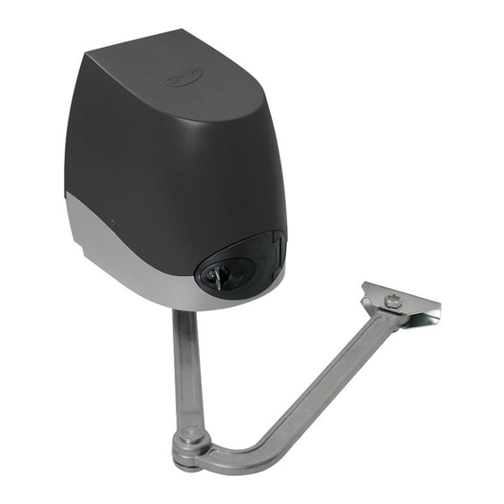
- Page 1 ARTEK GEAR MOTOR WITH ARTICULATED ARM FOR SWING GATES GEAR MOTOR WITH ARTICULATED ARM FOR SWING GATES INSTALLATION AND USE MANUAL 6-1624111 - rev. 0.0 - 15/09/2023 ENGLISH - Translated from the original language...
- Page 2 INDEX 1. GENERAL WARNINGS FOR THE INSTALLER 2. RESIDENTIAL APPLICATION 3. TECHNICAL SPECIFICATIONS 4. UTILISATION LIMITS 5. OVERALL DIMENSIONS 6. FIXING AND ADJUSTMENT OF MECHANICAL STOPS FOR LIMIT SWITCHES 7. PRELIMINARY CHECK 8. BRACKETS FIXING ON THE COLUMN AND ON THE GATE (drowning 1 and drowning 2) 9.
- Page 3 • As ARTEK is made specifically to control swing gates it is forbidden to use the product for different purposes or improperly. • Use original components only. ALLMATIC is not liable for damages if other components are used. • Make certain that the gate structure is solid and suitable for being mo- tor-driven.
- Page 4 2. RESIDENTIAL APPLICATION 4 - English - Translated from the original language 6-1624111 - rev. 0.0 - 15/09/2023...
-
Page 5: Technical Specifications
3. TECHNICAL SPECIFICATIONS Commercial name ARTEK 24V Motor supply 24Vdc Max. current requirement (A) Max. motor power (W) 90° Travel time (sec.) 16 - 20 Torque (Nm) Working temperature (°C) -20 ... +60 Work cycle (%) intensive IP protection level Weight (Kg) 4. - Page 6 6. FIXING AND ADJUSTMENT OF MECHANICAL STOPS FOR LIMIT SWITCHES If you want to use mechanical stops, they must be put on their own tracks on the lower part of the ARTEK motor. To adjust the stops, close the gate and slide the mechanical stop 1 until it is next to the motor arm.
-
Page 7: Preliminary Check
7. PRELIMINARY CHECK Before installing the motor, check the topics below: • Gate structure must be tough and there must not be any friction between the wing and its pivot. • Gate pivots must work correctly and be lubricated enough. •... - Page 8 OPENING 90° 155 ÷ 210 230 max 90° 155 ÷ 210 230 max 90° 155 ÷ 210 230 max 90° 155 ÷ 210 230 max 90° 155 ÷ 210 230 max 90° 155 ÷ 210 230 max 90° 155 ÷ 210 230 max 90°...
- Page 9 Drowning 2 9. FIXING THE GEARED MOTOR Unscrew the 4.2x9.5 screws and remove the cover (Fig. 3). Fit the geared motor on the base plate by the holes and lock it in place with the M8x90 screws and nuts (Fig. 4). Drowning 3 6-1624111 - rev.
- Page 10 Drowning 4 10. MOUNTING THE ARTICULATED ARM (Figures 5, 6, 7) The arm must be put in straight by the keyed shaft; position the 11 Ø x30 washer and lock the arm with the M10x28 screw. Release the geared motor by turning the key clockwise, opening the door 90° and pulling the release knob.
- Page 11 Articulated arm Shaft Drowning 5 RELEASE KNOB Drowning 6 Drowning 7 6-1624111 - rev. 0.0 - 15/09/2023 Translated from the original language - English - 11...
-
Page 12: Product Disposal
/allmaticsrl ALLMATIC S.r.l 32026 Borgo Valbelluna - Belluno – Italy @allmaticsrl Via dell’Artigiano, n°1 – Z.A.
Need help?
Do you have a question about the ARTEK 24V and is the answer not in the manual?
Questions and answers