
Related Manuals for Allmatic KALOS 50


Summary of Contents for Allmatic KALOS 50
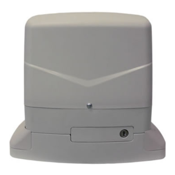
- Page 1 Gear-motor for sliding gates KALOS 50 KALOS 80 KALOS 120 KALOS 80 120 Vac KALOS 70 24V KALOS 110 24V INSTRUCTION MANUAL Made in italy...
-
Page 2: Table Of Contents
IMPORTANT REMARKS For any installation problems please contact Allmatic S.r.l. TEL. (+39) 0437 751175 has the right to modify the product without previous notice; it also declines any responsibility to damage or injury to people or things caused by improper use or wrong installation. -
Page 3: Models And Features
MODELS AND SPECIFICATIONS TECHNICAL DATA MODELLO KALOS 50 KALOS 80 KALOS 120 KALOS 80 120 Vac Control unit ERMES2/BIOS1 ERMES2/BIOS1 ERMES2/BIOS1 ERMES2/BIOS1 Power supply 230 Vac 230 Vac 230 Vac 120 Vac Maximum power 300 W 450 W 600 W... -
Page 4: Set Panel
SET PANEL Gear-motor Flash-light Antenna. Key selector Photocell Small columm Rack Limit switch Warning sign Stop locks PREVIOUS INSPECTIONS Before the installation starts, we suggest to carry out following inspections and operations: 1_ The gate framework must be strong and suitable. 2_ The gate must not show too many sideways slide skids during the running. -
Page 5: Overall Dimensions
OVERALL DIMENSIONS fig.1 MANUAL RUNNING 1_ Insert the key and turn it 90° in anticlockwise direction. 2_ Pull the knob till it is perpendicular to the gear-motor. fig.2... -
Page 6: Installation
INSTALLATION Respecting the overall size, fix to ground the base-plate through 4 sturdy screw-anchors (fig.n.3) or drown it into the concrete (fig.n.4). Plan for one or more sheathing for the passage of the power lines. fig.3 fig.4 NB: It is necessary to know the rack dimensions to can calculate exactly the counter-plate positioning. -
Page 7: Fixing
FIXING fig.5 Take the lid off unscrewing the screws (fig.5). Put the gear-motor on the plate. Insert the two socket head screws (fig.6). fig.6 It is important to lock the two socket head screws forcefully, making sure, that the gear- motor is steady on the ground, during the whole gate running. -
Page 8: Rack Assembling
RACK ASSEMBLING fig.8 90mm Release the gear-motor as indicated by the fig.1/2 and open entirely the gate. Put a rack element on the pinion gear and fasten it to the gate with screw and spacing bars. Move the gate manually bringing the pinion gear into line with the last spacing bar. Fasten the rack element for good. -
Page 9: Limit Switch Fixing
LIMIT SWITCH FIXING fig.10 The gate has to be equipped with stop locks at the opening and closing, which prevent the gate derail- ment. The stop lock position must assure that the limit switch brackets don’t collide with the pinion gear. Haul the gate manually at the opening leaving, depending on the gate weight, a crack from 30 to 50 mm between the main gate and mechanical stop. -
Page 10: Maintenance
MAINTENANCE DANGER: For any kind of maintenance, disconnect the power supply. The reduction grease is supplied with permanent lubrication grease and therefore does not require main- tenance. For the correct maintenance of the system where the reduction gear is operative, proceed as follows: Clean and clear from debris periodically the rail and its wheels. - Page 11 Allmatic congratulates with you for the excellent choice. We would like to Allmatic si congratula con Lei per la scelta effettuata, al fine di avere una durata remind our customers that in order to obtain the maximum operation of the massima dell’impianto Le ricordiamo di utilizzare solamente accessori, ricambi e...
- Page 12 Made in italy ALLMATIC S.r.l 32020 Lentiai - Belluno – Italy Via dell-Artigiano, n°1 – Z.A. Tel. 0437 751175 – 751163 r.a. Fax 0437 751065 http://www.allmatic.com - E-mail: info@allmatic.com 6-1624806 rev.1 09/07/2013...
Need help?
Do you have a question about the KALOS 50 and is the answer not in the manual?
Questions and answers