Table of Contents

Subscribe to Our Youtube Channel
Related Manuals for Allmatic TRAKTOR /I Series


Summary of Contents for Allmatic TRAKTOR /I Series
- Page 1 Series TRAKTOR /I OPERATOR FOR SLIDING GATES UP TO 2200 KG OPERATOR FOR SLIDING GATES UP TO 2200 KG INSTALLATION AND USE MANUAL TRAKTOR T/I TRAKTOR M/I Manual 6-1624970M - rev. 1 - 11/01/2023 ENGLISH - Translated from the original language...
- Page 2 INDEX 1. GENERAL WARNINGS FOR THE INSTALLER 1.1 - GENERAL ASPECTS OF SAFETY AND REGULATORY INCOMPATIBILITY 1.2 - SPECIFIC RISKS 1.3 - POTENTIAL DANGER POINTS FOR PERSONS 1.4 - GUIDELINES ON ELECTRICAL CONNECTIONS 1.5 - GUIDELINES FOR DOOR MOTORS 2. DESCRIPTION OF THE PRODUCT 2.1 - INTENDED USE 2.2 - TECHNICAL CHARACTERISTICS 2.3 - ANCHORAGE POINTS AND DIMENSIONS...
-
Page 3: Specific Risks
1. GENERAL WARNINGS FOR THE INSTALLER 1.1 - GENERAL ASPECTS OF SAFETY AND REGULATORY INCOMPATIBILITY • Any use of this product other than permitted use /intended use is prohibited. • The manufacturer shall not be liable for any damage caused as a result of improper use or as a result of installation not complying with the requirements of this manual. - Page 4 DANGER RISK OF ELECTRIC SHOCK AND/OR FIRE • Do not expose the equipment to liquid substances. • Do not exceed the temperature and humidity ranges specified in the technical data and leave the slit area ventilated. • Only use compatible accessories as indicated in the user manual. •...
- Page 5 1.3 - POTENTIAL DANGER POINTS FOR PERSONS No transit allowed for pedestrians during movement Danger of electric shock Danger of crushing Danger of crushing hands Manual 6-1624970M - rev. 1 - 11/01/2023 Translated from the original language - English - 5...
-
Page 6: Clamp Position
1.4 - GUIDELINES ON ELECTRICAL CONNECTIONS Prepare cable ducts on the installation site. The cables for the connection of the various devices in a typical plant are listed in the table below and must be suitable for the type of installation, for example we recommend a cable type H07RN-F for outdoor installation. CONNECTION CABLE LENGTH... - Page 7 1.5 - GUIDELINES FOR DOOR MOTORS The risk assessment must be carried out before installing the motor. The following are some checks and precautions commonly applicable to the systems of motorized doors/ gates; you must therefore, depending on the different situations, consider any additional risks and exclude those not applicable in accordance with the princi- ples of safety integration provided by the Machinery Directive.
-
Page 8: Description Of The Product
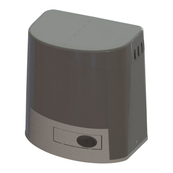
2. DESCRIPTION OF THE PRODUCT Irreversible operator complete with electronic board CT TRAKTOR INVERTER and electro-mechanical limit switch, for sliding gates with a maximum weight of 2200 kg. Drive electric motor with inverter technology for precise movement management. It has inputs for connection to control and safety devices, and outputs for management of a flashing light and courtesy light. -
Page 9: Technical Characteristics
2.2 - TECHNICAL CHARACTERISTICS Commercial name TRAKTOR T/I TRAKTOR M/I The product complies with the following Directives and 2014/53/EU Harmonized Standards Construction of the device Electronic control device to be incorporated. Purpose of the device Operating control device (non-safety) Control unit CT TRAKTOR INVERTER installed on board Software Class Power supply... -
Page 10: Fixing Plate
2.3 - ANCHORAGE POINTS AND DIMENSIONS 201,1 148,8 164,2 45,3 235,5 134,1 178,8 FIXING PLATE 89,4 220,6 10 - English - Translated from the original language Manual 6-1624970M - rev. 1 - 11/01/2023... -
Page 11: View Of The Product
2.4 - VIEW OF THE PRODUCT Description: External cover Pinion Protective cover of the board Release lever Electronic board Unlock key Plastic support for board Fixing plate complete with anchors Electro-mechanical limit switch Brackets for mechanical limit switch Manual 6-1624970M - rev. 1 - 11/01/2023 Translated from the original language - English - 11... - Page 12 2.5 - USE OF RELEASE LEVER FOR MANUAL MOVEMENT OF AUTOMATION RELEASE OF MOTOR TRANSMISSION MOTOR TRANSMISSION INSERTION 12 - English - Translated from the original language Manual 6-1624970M - rev. 1 - 11/01/2023...
-
Page 13: Typical Installation
2.6 - TYPICAL INSTALLATION Description: TRAKTOR Photocells Limit switch bracket Mechanical limit stop Rack Safety edge Key switch Internal area Flashing light with antenna External area Manual 6-1624970M - rev. 1 - 11/01/2023 Translated from the original language - English - 13... -
Page 14: Installation
3. INSTALLATION NOTE The following illustrations are just examples, as the space for fixing the automation and accessories varies depending on the dimensions. It is therefore up to the installer to choose the most suitable solution. The drawings refer to the automation installed to the left of the passage. 3.1 - INSTALLATION OF THE FIXING PLATE NOTE •... - Page 15 Place the fixing plate respecting the measurements in the drawing to ensure the correct transmission of the movement on the rack. Fill the concrete frame making sure that the plate remains on the surface. Allow the cement to solidify for at least 24 hours. RACK Remove the counter frame.
-
Page 16: Installation Of The Gear Motor
3.2 - INSTALLATION OF THE GEAR MOTOR NOTE • The electrical cables must pass through the appropriate hole at the bottom of the motor body. Remove the screws, remove the outer cover and unlock the motor transmission. Place the gear motor, aligning it, above the fixing plate. The threaded part of the hooks must pass through the slots of the gear motor body. - Page 17 3.4 - FIXING OF THE GEAR MOTOR Proceed to fixing only after adjusting and checking the pinion-rack coupling for the entire length of the gate. Secure the automation firmly to the mounting plate using the supplied washers and nuts. Make some manual movements to open and close the gate completely to verify that there are no anomalies. 3.5 - DETERMINATION OF LIMIT POINTS NOTE •...
- Page 18 4. CT TRAKTOR INVERTER CONTROL UNIT After the mechanical installation proceed with the connection of the cables to the control board. 4.1 - VIEW OF THE ELECTRONIC BOARD 1 2 3 28 29 30 Display and buttons FUSE4 - Line and motor protection (T 10 A) Led POWER ON Terminal for connecting the motor Radio Memory...
- Page 19 4.2 - MAIN POWER SUPPLY CONNECTION # TERMINAL FUNCTION RATING L - Phase cable Connect power from network distribution N - Neutral cable 230 Vac ± 10% 50/60 Hz PE - Earthing cable Reserved for connection performed by the manufacturer 4.3 - POWER SUPPLY CONNECTION ACCESSORIES # TERMINAL FUNCTION...
-
Page 20: Partial Opening
4.4 - ELECTRICAL CONNECTIONS OF CONTROL DEVICES # TERMINAL FUNCTION RATING COMMON CONTACT STEP-BY-STEP Connect a clean contact (voltage free) Normally PARTIAL OPENING Open. CLOSE Signal LED Normally OFF. OPEN Step-by-step function At each activation it performs sequentially OPEN-STOP-CLOSE-STOP. You can configure the execution mode using the basic parameter. Partial Opening function Performs a partial opening of the automation. - Page 21 4.5 - ELECTRICAL CONNECTIONS OF SAFETY DEVICES NOTE If EDGE, PH2, PH1 and STOP contacts are not used, they must be disabled using the DIP-SWITCH. This operation is possible by placing the corresponding selector in the ON position. # TERMINAL FUNCTION RATING COMMON CONTACT...
-
Page 22: Safety Edge
# TERMINAL FUNCTION RATING Connect mechanical (NC) or resistive (8.2 20 - 21 SAFETY EDGE Kohm) sensitive edges. Signal LED Normally On. Input SENSITIVE EDGE During the closing movement, it stops the movement of the automation and performs a reversal until the gate reaches the OPEN GATE position. - Page 23 4.6 - ELECTRICAL CONNECTIONS OF SIGNALLING DEVICES # TERMINAL FUNCTION RATING 28 - 29 Courtesy light MAX 230 Vac 60 W 30 - 31 Flashing lamp MAX 230 Vac 60 W The outputs are active during the opening and closing phases of the automation. Refer to the advanced parameters to configure the flashing mode and the lighting time of the courtesy light.
- Page 24 4.8 - ANTENNA CONNECTION AND RADIO COMMUNICATION WARNING • Do not place the control unit inside metal containers. • The maximum range can vary significantly in the presence of metal parts, in the presence of shielding between the transmitter and the control unit or in the presence of other devices that communicate at the same radio frequency.
- Page 25 5. PROGRAMMING DANGER The operations described in this chapter to finalize the installation must be carried out in the presence of voltage, therefore they must be carried out only by experienced personnel, qualified and taking all neces- sary precautions to ensure safe execution. Check that the operating area is free from any obstacles.
- Page 26 5.2 - DISPLAY MODE The display available in the control unit allows you to see a lot of information such as the status of the automation, the number of movements performed, the anomalies detected, etc. There are 4 types of views available. To switch from one type to another press the DOWN button.
-
Page 27: Standard View
5.3 - STANDARD VIEW DISPLAY DESCRIPTION Standby after first connection of the supply voltage. Automation in CLOSED GATE position. Automation stops in OPEN GATE position, without automatic closing. Automation stops in the PARTIAL OPENING position, without automatic closing. Automation in opening movement. Automation in closing movement. - Page 28 5.4 - SELECTION OF THE GATE CONFIGURATION DANGER RISK OF IMPACT, CRUSHING, HOOKING AND ENTRAPMENT • Set the DEF parameter according to the type of gate to be moved. • Make all necessary adjustments and checks in accordance with all applicable local, regional and national regulations and rules.
-
Page 29: Configuration Procedure
CONFIGURATION PROCEDURE MENU DOWN Make sure you are out of the programming menus. To exit, briefly press the MENU key until you see the status of the control panel. MENU DOWN Access the advanced menu by holding down the MENU key for at least 5 seconds. - Page 30 5.5 - LEARNING OF A REMOTE CONTROL The learning of a transmitter can be activated via the UP button of the control unit or via the hidden button of a transmitter already stored. The control unit can store up to 1000 remote controls (with memory card) and each of them can associate up to 4 functions, no more than one function per key available.
- Page 31 LEARNING WITH THE HIDDEN BUTTON OF A TRANSMITTER ALREADY LEARNED NOTE • The use of the hidden button, if present, of a transmitter already learned involves the entry in learning mode of all the units in which it is associated. Make sure that unwanted radio controls are not learned. •...
- Page 32 5.6 - LEARNING OF THE STROKES At the first installation it is necessary to perform a learning procedure to detect the total length of the stroke, the length of the slowdowns and all other areas of the installation necessary for the correct operation of the automation. LENGTH OF THE STROKE POSITION OF POSITION OF...
- Page 33 STANDARD LEARNING With standard learning, the control unit performs all the procedure and the calculation of slowdowns, which will be set with the same amplitude both in opening and closing ( see basic parameter " Lsi"). DANGER • Check that during the first movement the display displays "LOP" and the gate moves in the OPENING DIRECTION.
- Page 34 LEARNING WITH PERSONALIZED SLOWDOWNS With personalised learning, the slowdowns should be set during the learning process and the amplitudes in both directions will be independent. DANGER • Check that during the first movement the display displays "LOP" and the gate moves in the OPENING DIRECTION.
-
Page 35: Parameter List
5.7 - MENU OF BASIC FUNCTIONS To access the basic function menu, press and hold the MENU button for 1 to 3 seconds. Use the UP and DOWN buttons to scroll through the available features. While displaying a function, the control unit will alternate the display of the item to the value set in it. To change the value of the parameter you are viewing proceed as follows: •... - Page 36 Obstacle sensitivity on full speed movement NOTE • Too high a level of sensitivity could cause an abnormal behaviour of the automation depending on the force that the gear motor needs to move the automation. • Adjust this parameter according to current regulations. Set the sensitivity level for the impact sensor to intervene during gate movement.
- Page 37 Customize the action mode of the STEP-BY-STEP function. Normal: ("OPEN" - "STOP" - "CLOSE" - "STOP" - ...) Classic operation of the STEP-BY-STEP mode. During handling, a STEP-BY-STEP control involves stopping the automation. Alternate STOP: ("OPEN" - "STOP" - "CLOSE" - ...) Alternating operation with STOP in opening.
- Page 38 5.8 - MENU OF ADVANCED FUNCTIONS To access the advanced features menu, press and hold the MENU button for longer than 5 seconds. Use the UP and DOWN buttons to scroll through the available features. While displaying a function, the control unit will alternate the display of the item to the value set in it. To change the value of the parameter you are viewing proceed as follows: •...
- Page 39 PARAMETER VALUES DEFAULT 0 = Check input PH1 when "CLOSED GATE". 1 = Ignore input PH1 when "CLOSED GATE". Mode of intervention PH2 photocell input The engagement of the connected photocell on the PH2 input always involves the temporary stop of the movement, until the photo- cell is released.
- Page 40 Type of safety edge installed Select the type of security edge connected to the EDGE input. PARAMETER VALUES DEFAULT 0 = Mechanical type (Contact Normally Closed) 1 = Resistive type (8.2 Kohm) Mode of intervention EDGE input Customize the behaviour of the control unit following the intervention of the device connected to the EDGE input. Value 0: Only during the closing movement, performs a reversal of motion until reaching the position of "OPEN GATE".
- Page 41 Amplitude of partial opening Adjusts the amplitude of the partial opening as a percentage of the total stroke length. Partial opening is possible only starting from the position of "CLOSED GATE", using the appropriate command. Once reached the position of "PARTIAL OPENING" the display displays " PE ". PARAMETER VALUES DEFAULT...
- Page 42 PARAMETER VALUES DEFAULT 0 = Light on during operation + tCY 1 = Light off in "CLOSED" after tCY 2 = Light on for tCY 3 = Light off in "CLOSED" 4 = Proportional flashing Time for Courtesy Light Set a time to activate or wait for the courtesy light. Use it in combination with the "Courtesy light output configuration" parameter. PARAMETER VALUES DEFAULT...
- Page 43 Function of Mechanical Relaxation It allows you to perform a short reversal, the duration of which is customizable, once you reach the limit switch of opening or closing. This function is useful in case automation presses the mechanical blocks too hard and makes manual unlocking difficult. PARAMETER VALUES DEFAULT...
- Page 44 Cancellation of a single transmitter learned With this parameter you can erase a single transmitter already learned, using its memory location. If this value is not known, refer to the function "Display memory position of a learned transmitter". Follow these steps to cancel: •...
-
Page 45: Error Messages
6. ERROR MESSAGES NOTE Message reporting persists as long as the event persists or until the DOWN button is pressed or a handling command is executed. DISPLAY DESCRIPTION SOLUTION • Check that the limit switch is not blocked. Limit switch error: Opening and closing limit •... -
Page 46: Maintenance
7. MAINTENANCE DANGER • Before carrying out any cleaning, maintenance or replacement of parts, remove power to the automation. • The following points are specific to the maintenance of the gear motor. The list does not cover mainte- nance activities specific to the sliding gate/door. NOTE •... - Page 47 - ALLMATIC s.r.l, the reference for the relevant technical documentation, undertakes to transmit, in response to a duly reasoned request from the control authorities, information relevant to the quasi machine. - ALLMATIC s.r.l, référence de la documentation technique pertinente, s’engage à...
- Page 48 /allmaticsrl ALLMATIC S.r.l 32026 Borgo Valbelluna - Belluno – Italy @allmaticsrl Via dell’Artigiano, n°1 – Z.A. Tel. 0437 751175 – 751163 r.a. Fax 0437 751065 E-mail: info@allmatic.com @AllmaticSrl www.allmatic.com...
Need help?
Do you have a question about the TRAKTOR /I Series and is the answer not in the manual?
Questions and answers