Table of Contents
Advertisement
Available languages
Available languages
Quick Links
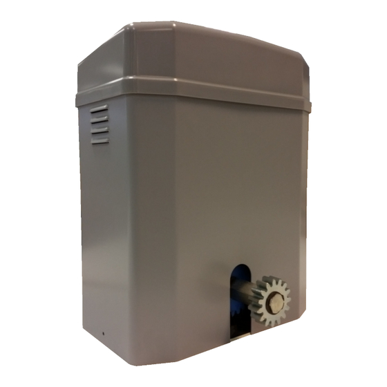
I2500
OPERATORE IRREVERSIBILE PER CANCELLI SCORREVOLI
IRREVERSIBLE OPERATOR FOR SLIDING GATES
OPERATEUR IRREVERSIBLE POUR PORTAILS COULISSANTES
OPERADOR IRREVERSIBLE PARA VERJAS CORREDERAS
SELBSTHEMMENDER TORANTRIEB FÜR SCHIEBETOREN
Operatore
Alimentazione
Operateur
Power Supply
Operator
Alimentation
Operador
Alimentacion
Torantrieb
Stromspannung
I2500/B
230V 50/60Hz
I2500/I
230V 50/60Hz
Centralina
Peso max cancello
Control unit
Max gate weight
Centrale de commande
Poids maxi portail
Centralita
Peso máx verja
Steuereinheit
Max Torgewicht
BIOS1
2500 kg / 5510 lbs
CT INVERTER
2500 kg / 5510 lbs
MADE IN ITALY
Spinta max
Coppia max
Max Thrust
Max torque
Poussée maxi
Couple max
Max Empuje
Coppia max
Max Schubkraft
Max. Drehmoment
132Kg / 292lbs
31,8 Nm
132Kg / 292lbs
31,8 Nm
Codice
Code
Code
Code
Codigo
12007101
12007102
Advertisement
Table of Contents

Related Manuals for Allmatic I2500 Series


Summary of Contents for Allmatic I2500 Series
- Page 1 I2500 OPERATORE IRREVERSIBILE PER CANCELLI SCORREVOLI IRREVERSIBLE OPERATOR FOR SLIDING GATES OPERATEUR IRREVERSIBLE POUR PORTAILS COULISSANTES OPERADOR IRREVERSIBLE PARA VERJAS CORREDERAS SELBSTHEMMENDER TORANTRIEB FÜR SCHIEBETOREN Operatore Alimentazione Centralina Peso max cancello Spinta max Coppia max Codice Operateur Power Supply Control unit Max gate weight Max Thrust Max torque...
- Page 2 2° - Per la sezione ed il tipo dei cavi ALLMATIC consiglia di utilizzare un 2° - As far as the cable section and the cable kind are concerned, ALLMATIC cavo di tipo H05RN-F con sezione minima di 1,5mm 2 e comunque di...
- Page 3 2° - Para la sección y el tipo de los cables, ALLMATIC aconseja utilizar cables 2° - En ce qui concerne la section et le type des câbles, le conseil de ALLMATIC de tipo H05RN-F con sección mínima de 1,5mm 2 e igualmente atenerse est celui d’utiliser un câble de type H05RN-F présentant une section...
- Page 4 Die in diesem Handbuch aufgeführten Daten sind ausschließlich empfohlene Hersteller haftet dagegen für Schäden infolge von Unfällen jeder Art, die auf die Werte. ALLMATIC behält sich das Recht vor, das Produkt zu jedem Zeitpunkt Fehlerhaftigkeit ihrer Produkte zurückzu führen sind, und zwar ausschließlich im vom italienischen Gesetz unabdingbar vorgesehenen Rahmen.
-
Page 5: Caratteristiche Tecniche
LAYOUT IMPIANTO A - Operatore I2500 B - Fotocellule esterne C - Cremagliera Modulo 4 D - Selettore a chiave E - Antenna radio F - Lampeggiatore H - Colonnina portafotocellula I - Fotocellula per protezione interna FIG. 1 L - Costa meccanica M - Costa meccanica con sistema wireless. - Page 6 INSTALLAZIONE I2500 CONTROLLO PRE-INSTALLAZIONE - IL CANCELLO DEVE MUOVERSI SENZA ATTRITI - N.B. È obbligatorio uniformare le caratteristiche del cancello alle norme e leggi vigenti. La porta può essere automatizzata solo se in buono stato e se rispondente alla norma EN 12604. - L’anta non deve presentare porte pedonali.
-
Page 7: Fissaggio Motore E Cremagliera
FISSAGGIO MOTORE E CREMAGLIERA La cremagliera va fissata a una certa altezza rispetto alla piastra di fissaggio del motore. Questa altezza può essere variata grazie a delle asole presenti sulla cremagliera. La registrazione in altezza viene fatta affinché il cancello durante il movimento, non si appoggi sull’ingranaggio di trazione del riduttore (Fig. -
Page 8: System Layout
SYSTEM LAYOUT FIG. 1 A - I2500 operator B - Photocells (external) C - Rack M4 D - Key selector E - Tuned antenna F - Flashing lamp H - Galvanized column for photocells I - Photocells (internal) L - Safety edge fixed to column M - Safety edge with wireless system TECHNICAL FEATURES TECHNICAL DATA... -
Page 9: Command Type
INSTALLATION I2500 CHECKING BEFORE THE INSTALLATION !! THE GATE SHALL MOVE FRICTIONLESS !! N.B.: Gate features must be uniformed with the standards and laws in force. The door/gate can be automated only if it is in a good condition and its conditions comply with the EN 12604 norm. -
Page 10: Motor And Rack Fitting
MOTOR AND RACK FITTING The rack shall be fitted over the motor support, at a certain distance from It. Its height can be adjusted thanks to the holes In the rack. The height adjusting is necessary to prevent the gate leaning on the driving gear (5 and 6). -
Page 11: Caractéristiques Techniques
SCHÉMA DÉTAILLÉ DE L’INSTALLATION A - Operateur I2500 B - Photocellules externe C - Cremaillere M4 D - Selecteur E - Antenne radio F - Signal electrique H - Poteau zingué pour photocellules I - Photocellules interne FIG. 1 L - Barre palpeuse mécanique fixé sur pilier M - Barre palpeuse avec système wireless CARACTÉRISTIQUES TECHNIQUES CARACTERISTIQUES TECHNIQUES... - Page 12 INSTALLATION I2500 CONTRÔLE PRÉ-INSTALLATION !! LE PORTAIL DOIT SE DÉPLACER SANS FROTTER !! N.B. Il est impératif d’uniformiser les caractéristiques du portail avec les normes et les lois en vigueur. La porte peut être automatisée seulement si elle est en bon état et qu’elle est conforme à...
- Page 13 FIXATION MOTEUR ET CRÉMAILLÈRE La crémaillère doit être fixée à une certaine hauteur par rapport à la base du moteur. Cette hauteur peut être modifiée grâce à des boutonnières qui sont présentes sur la crémaillère. Le réglage en hauteur est effectué afin que le portail ne s’appuie pas sur l’engrenage de traction du réducteur (Fig.
-
Page 14: Características Técnicas
DISPOSICIÒN DE LA INSTALACIÒN A - Operador I2500 B - Fotocélulas externas C - Cremallera Módulo 4 D - Interruptor de llave E - Antena de radio F - Intermitente H - Columnas para las fotocélulas I - Fotocélulas internas FIG. - Page 15 INSTALACIÓN I2500 CONTROL PRE-INSTALACIÓN ¡¡LA VERJA TIENE QUE MOVERSE SIN ROCES!! IMPORTANTE. Es obligatorio uniformar las características de la verja a las normas y leyes en vigor. La puerta puede ser automatizada sólo si se encuentra en buen estado y responde a la norma EN 12604. - La puerta no tiene que tener puertas peatonales.
-
Page 16: Conexión A Tierra
ANCLAJE MOTOR Y CREMALLERA La cremallera se tiene que anclar a una determinada altura respecto al soporte del motor. Dicha altura se puede variar gracias a unos ojales presentes en la cremallera. El ajuste de la altura se efectúa para que la verja durante el movimiento no se apoye sobre el engranaje de tracción del K (Fig. -
Page 17: Technische Eigenschaften
ANLAGEN LAY-OUT A - Torantrieb I2500 B - Lichtschranke Toraussenseitig C - Zahnstange M4 D - Schlusselschalter E - Antenne F - Blinkleuchte H - Verzinkte Metallsäule als Photozellentrager I - Lichtschranke - Torinnenseitig FIG. 1 L - Sicherheitskontaktleiste auf dem Schiebetor M - Sicherheitskontaktleiste mit Wireless System TECHNISCHE EIGENSCHAFTEN I2500... - Page 18 INSTALLATION I2500 VOR DER MONTAGE AUSZUFÜHRENDE ÜBERPRÜFUNGEN !! DAS TOR MUSS REIBUNGSFREI LAUFEN !! ANMERKUNG: Es ist erforderlich, die Charakteristiken des Tors an die geltenden Normen und Gesetze anzupassen. Das Tor kann nur automatisch Angeschlossen werden, wenn es in einem einwandfreien Zustand ist und der EN12604 entspricht.
- Page 19 MOTORBEFESTIGUNG UND ZAHNSTANGE Die Zahnstange muß in bestimmten Abstand von der Verankerungsplatte befestigt werden. Die Zahnstange darf nicht angeschweißt, sondern nur mit Hilfe von Gewindeschrauben an dem Gittertor befestigt werden. Die Höheneinstellung soll verhindern, daß das Gittertor auf dem Antriebszahnrad des Antriebes aufliegt.
-
Page 20: Made In Italy
MADE IN ITALY ALLMATIC S.r.l 32020 Lentiai - Belluno – Italy Via dell’Artigiano, n°1 – Z.A. Tel. 0437 751175 – 751163 r.a. Fax 0437 751065 http://www.allmatic.com - E-mail: info@allmatic.com 6-1624012 rev.0 09/11/2015...
Need help?
Do you have a question about the I2500 Series and is the answer not in the manual?
Questions and answers