Table of Contents
Advertisement
Available languages
Available languages
Quick Links
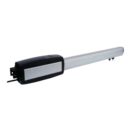
ATTUATORE IRREVESIBILE
PER CANCELLI E PORTE AD
ANTE BATTENTI
AX-222
ATTENZIONE!! Prima di effettuare l'installazione, leggere attentamente questo
manuale che è parte integrante di questa confezione.
I nostri prodotti se installati da personale specializzato idoneo alla
valutazione dei rischi, rispondono alle normative UNI EN 12453-EN 12445
Il marchio CE è conforme alla direttiva europea
CEE 89/336 + 92/31 + 93/68 D.L. 04/12/1992 N. 476.
6-1624840 rev.12 09-07-2013
Advertisement
Chapters
Table of Contents

Related Manuals for Allmatic AX-222


Summary of Contents for Allmatic AX-222
- Page 1 ATTUATORE IRREVESIBILE PER CANCELLI E PORTE AD ANTE BATTENTI AX-222 ATTENZIONE!! Prima di effettuare l'installazione, leggere attentamente questo manuale che è parte integrante di questa confezione. I nostri prodotti se installati da personale specializzato idoneo alla valutazione dei rischi, rispondono alle normative UNI EN 12453-EN 12445 Il marchio CE è...
-
Page 2: Table Of Contents
Composizione dell’imballo ..............Prospetto generale ................Dati tecnici ..................Dimensioni ..................Collegamento tipo e sezione cavi ............Considerazione per l’installazione ............Modalità’ di installazione ..............Inconvenienti : cause e soluzioni............Suggerimenti e sicurezza ..............CONTENUTO DELL’IMBALLO 1- ATTUATORE 1- KIT STAFFE DI FISSAGGIO 1- CHIAVE SBLOCCO 1- CONDENSATORE (per versioni 230Vca) 6-1624840 rev.12 09-07-2013... -
Page 3: Dati Tecnici
Esempio di installazione 1- Attuatori 5- Fotocellula interna 2- Fotocellula esterna 6- Quadro di comando 3- Lampeggiatore 7- Selettore a chiave 4- Antenna 8- Radiocomando DATI TECNICI 200 Kg Peso Max anta 2,50 mt Lunghezza Max anta 24Vdc 230 Vac Alimentazione motore 50 W 200 W... -
Page 4: Dimensioni
DIMENSIONI COLLEGAMENTO TIPO E SEZIONE CAVI 2X1,5mm2 (24 Vdc ) 4X1,5mm2 (230 Vca ) 2X0,75mm2 RX fotocellula TX fotocellula 4X0,75mm2 2X0,75mm2 4X0,75mm2 3X1,5mm2 Linea 230V 6-1624840 rev.11 01-07-2013 6-1624840 rev.12 09-07-2013... -
Page 5: Considerazione Per L'installazione
CONSIDERAZIONI PER L’INSTALLAZIONE Le operazioni di installazione e collaudo devono essere eseguite solo da personale · qualificato ai fini di garantire la corretta e sicura funzionalità del cancello automatico. La casa costruttrice, declina ogni responsabilità per i danni derivati da eventuali errate ·... - Page 6 INSTALLAZIONE PIASTRE DI FISSAGGIO Fissare la piastra posteriore al pilastro.(FIG. 1) Ancorare la parte posteriore (FIG. 1) dell’attuatore alla piastra e fissarla saldamente. ( FIG. 2) (FIG. 2) (FIG. 3) Attenzione! Nel determinare l'altezza da terra in cui fissare la piastra sul pilastro(FIG.1), tenere conto dell'altezza che si andrà...
-
Page 7: Inconvenienti-Cause E Soluzioni
INCONVENIENTI-CAUSE E SOLUZIONI INCONVENIENTE CAUSA PROBABILE SOLUZIONE Alimentazione di rete Controllare l’interrutore 230 volt assente principale Controllare eventuali selettori o comandi di Presenza di STOP di STOP. Se non utilizzati emergenza verificare ponticello su Ad un comando con ingresso contatto STOP il radiocomando o con su centralina il selettore a chiave,... - Page 8 AVVERTENZE PER LA SICUREZZA Le presenti avvertenze sono parti integranti ed essenziali del prodotto e devono essere consegnate all’utilizzatore. Leggerle attentamente in quanto forniscono importanti indicazioni riguardanti l’installazione, l’uso e la manutenzione. E’ necessario conservare il presente modulo e trasmetterlo ad eventuali subentranti nell’uso dell’impianto. L’errata installazione o l’utilizzo improprio del prodotto può...
- Page 9 IRREVERSIBLE OPERATOR FOR SWING GATES AND DOORS AX-222 WARNING!! Before installing, thoroughly read this manual that is an integral part of the pack Our products if installed by qualified personnel capable to evaluate risks, comply with norms UNI EN 12453, EN 12445 The CE mark conforms to European directive EEC 89/336 + 92/31 + 93/68 D.L.
- Page 10 ................PACKING CONTENTS ..... VIEW OF TYPICAL AUTOMATION AND NAMES OF COMPONENTS ..................TECHNICAL DATA ..................DIMENSIONS .......... TYPICAL CONNECTION AND CABLE SECTION ........... CONSIDERATIONS FOR INSTALLATION ..................INSTALLATION ................TROUBLESHOOTING ................SAFETY PRECAUTIONS PACKING CONTENTS 1- OPERATOR 1- KIT FASTENING PLATES AND RELATIVE ACCESSORIES 1- UNLOCKING KEY 1- CONDENSER (230Vca)
-
Page 11: View Of Typical Automation And Names Of Components
VIEW OF TYPICAL AUTOMATION AND NAMES OF COMPONENTS Optimal installation 1- Operator 5- Internal photocell 2- External photocell 6- Electronic control unit 3- Flashing warning light 7- Key-switch 4- Antenna 8- Remote control TECHNICAL DATA 200 Kg Max. weight of gate 2,50 mt Max. -
Page 12: Dimensions
DIMENSIONS TYPICAL CONNECTION AND CABLE SECTION 2X1,5mm2 (24 Vdc ) 4X1,5mm2 (230 Vca ) 2X0,75mm2 RX Photocell TX Photocell 4X0,75mm2 2X0,75mm2 4X0,75mm2 3X1,5mm2 230V Line 6-1624840 rev.1 0 -07-20 6-1624840 rev.1 0 -07-20... -
Page 13: Considerations For Installation
CONSIDERATIONS FOR INSTALLATION · The installation and testing operations must be performed solely by qualified personnel in order to guarantee the proper and safe operation of the automatic gate. · The company declines any responsibility for damage caused by incorrect installations due to incompetence and/or negligence. - Page 14 INSTALLATION OF FASTENING PLATES Fix the back plate to the pillar.(FIG. 1) Anchor the rear part of the piston to the plate and fasten it firmly (FIG. 1) ( FIG. 2) (FIG. 2) (FIG. 3) Warning! When establishing the height off the ground at which to fasten the plate (FIG.1) onto the post, keep in mind the height at which the plate will be fastened (FIG.3) for anchoring the piston to the gate and that the plate must be fastened 50 mm below that on the post to obtain horizontal levelling.
-
Page 15: Troubleshooting
TROUBLESHOOTING SOLUTION PROBLEM PROBABLE CAUSE 230 volt mains voltage Check master switch absent Check for any STOP selectors or commands. Emergency STOP present If not used, check jumper On giving a command with on STOP contact input on the remote the control board control or with the key-switch, the gate... -
Page 16: Safety Precautions
SAFETY PRECAUTIONS These warnings are an essential, integral part of the product and must be given to the user. They provide important indications on the installation, use and maintenance and must be read carefully. This form must be preserved and passed on to subsequent users of the system. The incorrect installation or improper use of the product may be dangerous. - Page 17 PISTON ELECTROMECANIQUE POUR GRILLES ET PORTES A BATTANTS AX-222 ATTENTION! Avant d’effectuer l’installation, lire attentivement le présent manuel qui fait partie intégrante de cet emballage. Nos produits si installés par personnel qualifié capable d'évaluer les risques, sont conformer à la norme UNI EN 12453, EN 12445 Le marquage CE est conforme à...
-
Page 18: Composition De L'emballage
TABLE DES MATIÈRES Composition de l’emballage ..............Tabbleau général .................. Caractéristiques techniques..............Dimensions.................... Branchement et section câbles ............Considérations pour l’installations ............Modalités d’installation ................. Inconvénients: causea et solutions ............. Suggestions et sécurités ..............CONTENU DE L’EMBALLAGE 1- PISTON 1- KIT PLAQUES DE FIXATION ET ACCESSOIRES 1- CLEF DE DÉBLOCAGE 1- CONDENSATEUR (230VCA) -
Page 19: Tabbleau Général
TABLEAU AUTOMATION TYPE ET NOMENCLATURE COMPOSANTS Installation optimale 1- Pistons 5- Photocellule interne 2- Photocellule d’extérieur 6- Centrale électronique 3- Clignotant 7- Sélecteur à clef 4- Antenne 8- Commande radio CARACTÉRISTIQUES TECHNIQUES 200 Kg Poids maxi battant 2,50 mt Largeur maxi battant 24Vdc 230 Vac Alimentation moteur... -
Page 20: Dimensions
DIMENSIONS BRANCHEMENT TYPE ET SECTION CÂBLES 2X1,5mm2 (24 Vdc ) 4X1,5mm2 (230 Vca ) 2X0,75mm2 RX photocellule TX photocellule 4X0,75mm2 2X0,75mm2 4X0,75mm2 3X1,5mm2 230V Ligne 6-1624840 rev.11 01-07-2013 6-1624840 rev.12 09-07-2013... -
Page 21: Considérations Pour L'installations
CONSIDÉRATIONS POUR L’INSTALLATION · Les opérations d’installation et de contrôle doivent être effectuées uniquement par du personnel qualifié en vue d’assurer le fonctionnement correct et sûr de la grille automatique. · La société , décline toute responsabilité concernant les dommages découlant d’une mauvaise installation par incapacité... - Page 22 INSTALLATION DES PLAQUES DE FIXATION Fixer la plaque postérieur sur le pilon.(FIG. 1) Ancrer la partie arrière du piston à la plaque et la fixer solidement (FIG. 1) ( FIG. 2) (FIG. 2) (FIG. 3) Attention! En déterminant la hauteur du sol où fixer la plaquette au pilier(fig.1), tenir compte de la hauteur où...
-
Page 23: Inconvénients: Causea Et Solutions
INCONVÉNIENTS – CAUSES ET SOLUTIONS INCONVÉNIENT CAUSE PROBABLE SOLUTION Contrôler l’interrupteur Alimentation secteur principal 230 volts absente Contrôler les commandes éventuelles ou les commandes de STOP. Présence d’un arrêt S’ils ne sont pas utilisés, d’urgence contrôler le jumper sur En présence d’une entrée contact STOP sur commande avec la la centrale... -
Page 24: Suggestions Et Sécurités
CONSIGNES DE SECURITE Les présentes consignes font partie intégrante du produit et doivent être remises à l’utilisateur. Les lire attentivement car elles fournissent des indications importantes concernant l’installation, l’utilisation et l’entretien. Conserver le présent document et le remettre aux propriétaires suivants de l’installation. - Page 25 ACTUADOR IRREVERSIBLE PARA PUERTAS CON HOJAS BATIENTE. AX-222 Atención! Antes de efectuar la instalación, leer atentamente el presente manual, que es parte integrante de este producto. Nuestros productos si son instalados por personal cualificado capaz de la evaluación de riesgos, cumplen con la norma UNI EN 12453, EN 12445...
- Page 26 Composición embalaje ................ Prospecto general ................Datos Técnicos..................Dimensión .................... Conexiones y secciones de cables ............ Consideraciones para la instalación ............ Modalidad de instalación ..............Inconvenientes : causas y soluciones..........Sugerencias y seguridad ..............CONTENIDO EMBALAJE Actuador Kit placas de fijación y accesorios llave de desbloqueo Condensador (230Vca)
-
Page 27: Datos Técnicos
PROSPECTO AUTOMATISMO TIPO Y NOMENCLATURA COMPONENTES Instalación óptima 1- Actuador 5- Fotocélula interna 2- Fotocélula externa 6- Central electrónica 3- Indicador luminoso intermitente 7- Selector de llave 4- Antena 8- Emisor DATOS TECNICOS Peso máximo por hoja 200 Kg Ancho máximo de la hoja 2,50 mt Alimentación del Motor 24Vdc... -
Page 28: Dimensión
DIMENSIONES CONEXION TIPO Y SECCION CABLES 2X1,5mm2 (24 Vdc ) 4X1,5mm2 (230 Vca ) 2X0,75mm2 RX Fotocélula TX Fotocélula 4X0,75mm2 2X0,75mm2 4X0,75mm2 3X1,5mm2 Alimentación 230 Vac. 6-1624840 rev.1 0 -07-20 6-1624840 rev.1 0 -07-20... -
Page 29: Consideraciones Para La Instalación
CONSIDERACIONES PARA LA INSTALACIÓN · Las operaciones de instalación y ensayo deben ser efectuadas únicamente por personal cualificado para garantizar un funcionamiento correcto y seguro de la cancela automática. · La Empresa, se exime de toda responsabilidad por los daños derivados de instalaciones erradas por incapacidad y/o negligencia. - Page 30 INSTALACION DE LAS PLACAS DE FIJACION Fijar la placa suministrada en el pilar .(FIG. 1) Anclar la parte trasera del pistón a la placa (FIG. 1) y fijarla firmemente . ( FIG. 2) (FIG. 2) (FIG. 3) Atención! Al determinar la altura del suelo a la placa (Fig.1) que va en la pared, tener en cuenta que el soporte delantero del motor en la puerta irá...
-
Page 31: Inconvenientes- Causas Y Soluciones
INCONVENIENTES- CAUSAS Y SOLUCIONES INCONVENIENTE CAUSA PROBABLE SOLUCION Alimentación de red 230 Controlar el interruptor volt ausente principal Controlar los selectores o mandos de STOP. Presencia de STOP de Si no utilizados, controlar emergencia en la central, el puente en entrada Ante un mando emitido contacto STOP con el radiomando o con... - Page 32 ADVERTENCIAS PARA LA SEGURIDAD Las presentes advertencias constituyen una parte integrante y esencial del producto y deben ser remitidas al usuario. Leerlas atentamente, ya que brindan importantes indicaciones relativas a la instalación, al uso y al mantenimiento. Es necesario conservar el presente módulo y transmitirlo a los nuevos utilizadores del equipo.
Need help?
Do you have a question about the AX-222 and is the answer not in the manual?
Questions and answers