Advertisement
Available languages
Available languages
Quick Links
KINEO 400
MOTORIDUTTORE IRREVERSIBILE PER
CANCELLI A BATTENTE
MOTORÉDUCTEUR IRREVERSIBLE POUR
PORTAILS à BATTANTS
IRREVERSIBLE GEARMOTOR FOR WING
GATES
MOTORREDUCTOR IRREVERSIBLE PARA
CANCELAS A HOJAS
6-1624842 /Rev. 8
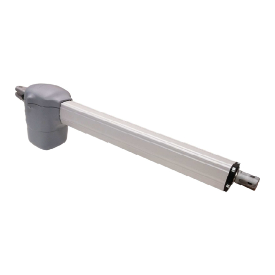
Motoriduttore
Gearmotor
Motoréducteur
Motorreductor
KINEO 400
Alimentazione
Larghezza max anta
Power Supply
Max wing width
Alimentation
Largeur max du battant
Alimentación
Longitud máx hoja
230V 50/60Hz
Peso max anta
Max wing weight
Poids max du battant
Peso máx hoja
3 m
250 Kg / 550 lbs
Spinta max
Codice
Max Thrust
Poussée maxi
Max Empuje
Codigo
2900 N
12007446
Code
Code
Advertisement

Related Manuals for Allmatic KINEO 400


Summary of Contents for Allmatic KINEO 400
- Page 1 KINEO 400 MOTORIDUTTORE IRREVERSIBILE PER CANCELLI A BATTENTE MOTORÉDUCTEUR IRREVERSIBLE POUR PORTAILS à BATTANTS IRREVERSIBLE GEARMOTOR FOR WING GATES MOTORREDUCTOR IRREVERSIBLE PARA CANCELAS A HOJAS 6-1624842 /Rev. 8 Motoriduttore Alimentazione Larghezza max anta Peso max anta Spinta max Codice Gearmotor...
- Page 2 In any case, the IEC 364 standard and Installation regulations accidentale (ad esempio installandolo dentro quadro chiuso a chiave). 2° - Per la sezione ed il tipo dei cavi ALLMATIC consiglia di utilizzare un cavo di In force In your Country.
- Page 3 à clé). normas internacionales. Este dispositivo tiene que estar protegido contra 2° - En ce qui concerne la section et le type des câbles, le conseil de ALLMATIC cierres accidentales (por ejemplo instalándolo dentro de un panel cerrado est celui d’utiliser un câble de type H05RN-F présentant une section minimale...
- Page 4 LAYOUT IMPIANTO A (M2) A (M1) FIG. 1 A - Motoriduttore KINEO 400 F - Fotocellula per protezione esterna B - Centrale di comando BIOS con box G - Fotocellula per protezione interna C - Selettore a chiave H - Colonnina portafotocellula...
- Page 5 INSTALLAZIONE KINEO 400 CONTROLLO PRE-INSTALLAZIONE - IL CANCELLO DEVE MUOVERSI SENZA ATTRITI - Componenti da installare secondo la norma EN12453 USO DELLA CHIUSURA N.B.: è obbligatorio uniformare le caratteristiche del cancello alle norme e leggi vigenti. La porta può essere automatizzata solo se in buono stato e se...
- Page 6 FISSAGGIO PIASTRA POSTERIORE ALLA COLONNA Piastra anteriore Piastra posteriore Fissare la piastra posteriore alla colonna (Fig. 4), rispettando le quote stabilite. Se la colonna è in ferro le si può avvitare direttamente l’attacco utilizzando tre viti filettate M8. Se la colonna è in cemento fissare l’attacco con tre viti ad espansione di Ø 8 mm. Dopo aver fissato la piastra, ancorare la parte posteriore dell’attuatore alla piastra e fissarla saldamente (Fig.
- Page 7 RISOLUZIONE PROBLEMI PROBLEMA CAUSA PROBABILE SOLUZIONE Alimentazione di rete. Controllare l’interrutore principale. Controllare eventuali selettori o comandi di STOP. Presenza di STOP di emergenza. Se non utilizzati verificare ponticello su ingresso contatto STOP su centralina. Ad un comando con il radiocomando o con il selettore a chiave, il cancello non si apre o il Fusibile bruciato.
- Page 8 SYSTEM LAYOUT A (M2) A (M1) FIG. 1 A - KINEO 400 gearmotor F - Photocells (external) B - BIOS control unit with box G - Photocells (internal C - Key selector H - Column for photocell D - Tuned antenna...
- Page 9 KINEO 400 INSTALLATION CHECKING BEFORE THE INSTALLATION - THE GATE SHALL MOVE FRICTIONLESS - Parts to install meeting the EN 12453 standard USE OF THE SHUTTER Note: gate features must be uniformed with the standards and laws in force. Skilled persons...
- Page 10 FIXING OF THE REAR PLATE TO THE COLUMN Front plate Rear plate Fix the rear plate to the column (Fig. 4) in accordance to the desired coordinates. In case an iron pillar is available, screw directly onto the column the plate with 3 screws M8..
- Page 11 TROUBLESHOOTING PROBLEM PROBABLE CAUSE SOLUTION 230 volt mains voltage absent. Check the main switch. Check for any STOP selectors or commands. Emergency STOP present. If not used, check the jumper on the STOP input of By giving a command with the remote control or the control unit.
- Page 12 SCHÉMA DÉTAILLÉ DE L’INSTALLATION A (M2) A (M1) FIG. 1 A - Motoréducteur KINEO 400 F - Photocellules externes B - Centrale de commande BIOS en box G - Photocellules internes C - Selecteur à clé H - Supports pour photocellules D - Antenne radio I - Arrêt mécanique en ouverture...
- Page 13 INSTALLATION KINEO 400 CONTRÔLE PRE-INSTALLATION - LE PORTAIL DOIT SE DÉPLACER SANS FROTTER - Parties à installer conformément à la norme EN12453 USAGE DE LA FERMETURE N.B.: il est impératif d’uniformiser les caractéristiques du portail avec les Personne expertes normes et les lois en vigueur. La porte peut être automatisée seulement si elle...
- Page 14 INSTALLATION DE LA PLAQUE POSTÉRIEURE SUR LE PILIER Plaque antérieure Plaque postérieure Fixer la plaque postérieure sur le pilier (Fig. 4), en respectant les quotas prévus. Si le poteau est en fer, il est possible de visser directement l’attache en utilisant 3 vis filetées M8.
- Page 15 RESOLUTION DES PROBLEMES PROBLÈME CAUSE PROBABLE SOLUTION Alimentation de réseau. Vérifiez l’interrupteur principal. Vérifiez d’éventuels sélecteurs ou commandes de Présence de STOP d'émergence. STOP. Si non utilisés, vérifiez le jumper sur l’entrée contact STOP sur la centrale de commande. Lors d’une commande avec l’émetteur ou avec le sélecteur à...
- Page 16 DISPOSICIÒN DE LA INSTALACIÒN A (M2) A (M1) FIG. 1 A - Motorreductor KINEO 400 F - Fotocélulas externas B - Cuadro de mando BIOS con box G - Fotocélulas internas C - Selector a llave H - Columnas para las fotocélulas D - Antena I - Bloqueo mecánico de apertura...
- Page 17 INSTALACIÓN KINEO 400 CONTROL PRE-INSTALACIÓN - LA VERJA TIENE QUE MOVERSE SIN ROCES - Componentes a instalar según la norma EN12453 USO DEL CIERRE N.B.: es obligatorio uniformar las características de la verja a las normas y leyes Personas expertas Personas en vigor.
- Page 18 FIJACION PLANCHA POSTERIOR A LA COLUMNA Plancha anterior Plancha posterior Fijar la plancha posterior a la columna (Fig. 4), respetando las medidas establecidas. Si la columna es de hierro se puede atornillar directamente el anclaje utilizando tres tonillos fileteados M8. Si la columna es de cemento fijar el anclaje con tres tornillos de expansión de Ø...
- Page 19 SOLUCION PROBLEMAS INCONVENIENTE CAUSA PROBABLE SOLUCION Alimentación de red. Controlar el interruptor principal. Controlar los selectores o mandos de STOP. Si no Presencia de STOP de emergencia. utilizados, controlar en la centralita, el puente en entrada contacto STOP. Ante un mando emitido con el radiomando o con Sustituirlo por otro fusible con las mismas el selector de llave, la cancela no abre o el motor Fusible quemado.
- Page 20 KINEO 400 MOTORIDUTTORE IRREVERSIBILE PER CANCELLI A BATTENTE MOTORÉDUCTEUR IRREVERSIBLE POUR PORTAILS à BATTANTS IRREVERSIBLE GEARMOTOR FOR WING GATES MOTORREDUCTOR IRREVERSIBLE PARA CANCELAS A HOJAS NEPOVRATNI MOTOR S PRIJENOSNIKOM ZA KRILNA VRATA 6-1624842 /Rev. 8 Larghezza max anta Alimentazione Peso max anta...
- Page 21 NACRT SISTEMA A (M2) A (M1) SLIKA 1 A - KINEO 400 motor s prijenosnikom F - Fotoćelije (vanjske) B - BIOS kontrolna jedinica sa kutijom G - Fotoćelije (unutarnje) C -Birač tipki H - Stub za fotoćelije D - Sinkronizirana antena I - Mehanički graničnik (otvaranje)
- Page 22 KINEO 400 INSTALACIJA PROVJERA PRIJE INSTALACIJE - VRATA TREBA DA SE OTVARAJU BEZ TRENJA- Dijelovi za instalaciju u skladu sa standardom EN12453 KORIŠTENJE PREKIDAČA Napomena: odlike kapije moraju biti usklađenje sa standardima i zakonima na Obučene osobe snazi. Vrata/kapija može biti automatizirana samo pod uslovom da se nalazi u VRSTA KOMANDE Neograničena...
- Page 23 PRIČVRŠĆIVANJE STRAŽNJE PLOČE NA STUB Prednja ploča Stražnja ploča Pričvrstite stražnju ploču na stub (Slika 4) u skladu sa željenim koordinatama. U slučaju da je dostupan željezni stup, vijkom direktno na stup pričvrstite ploču s 3 vijka M8 .. U slučaju da trebate pričvrstiti nosač na betonski stub, upotrijebite pričvrsnu ploču koja će se pričvrstiti s 3 Fischer vijcima Ø...
- Page 24 RJEŠAVANJE PROBLEMA VJEROJATNI UZROK RJEŠENJE PROBLEM Nema mrežnog napona od 230 V. Provjerite glavni prekidač. Provjerite ima li STOP selektora ili naredbi. Prisutan STOP za hitan slučaj. Ako se ne koristi, provjerite kratkospojnik na STOP Davanjem naredbe daljinskim upravljačem ili ulazu upravljačke jedinice.
- Page 28 ALLMATIC S.r.l 32026 Borgo Valbelluna - Belluno – Italy Via dell’Artigiano, n°1 – Z.A. Tel. 0437 751175 – 751163 r.a. Fax 0437 751065 www.allmatic.com - E-mail: info@allmatic.com...
Need help?
Do you have a question about the KINEO 400 and is the answer not in the manual?
Questions and answers