Graco Husky 307 Instructions-Parts List Manual
Air-operated diaphragm pumps
Hide thumbs
Also See for Husky 307:
- Instructions manual (38 pages) ,
- Instructions-parts list manual (22 pages) ,
- Instructions-parts list (4 pages)
Table of Contents
Advertisement
Instructions–Parts List
ACETAL AND POLYPROPYLENE
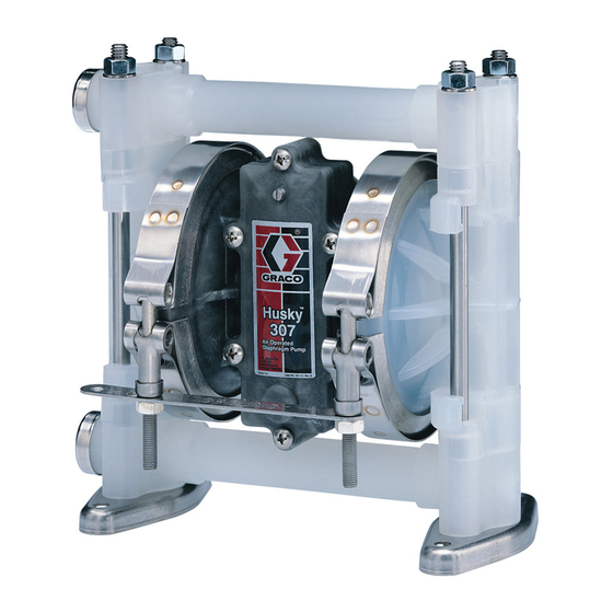
Husky™ 307 Air–Operated
Diaphragm Pumps
100 psi (0.7 MPa, 7 bar) Maximum Fluid Working Pressure
100 psi (0.7 MPa, 7 bar) Maximum Air Input Pressure
*Model No. D31
*Model No. D32
*Model No. D3A
*Model No. D3B
* To determine the Model No. for your pump and for additional models, refer to the Pump Matrix
on page 26.
Patent No.
US 5,240,390
US 5,280,808
Important Safety Instructions
Read all warnings and instructions in this manual.
Save these instructions.
Acetal Pumps, Series E
Polypropylene Pumps, Series E
Acetal BSPT Pumps, Series E
Polypropylene BSPT Pumps, Series E
308553AF
01428B
Advertisement
Table of Contents

Related Manuals for Graco Husky 307


Summary of Contents for Graco Husky 307
- Page 1 Instructions–Parts List ACETAL AND POLYPROPYLENE Husky™ 307 Air–Operated Diaphragm Pumps 308553AF 100 psi (0.7 MPa, 7 bar) Maximum Fluid Working Pressure 100 psi (0.7 MPa, 7 bar) Maximum Air Input Pressure *Model No. D31 Acetal Pumps, Series E *Model No. D32 Polypropylene Pumps, Series E *Model No.
-
Page 2: Table Of Contents
D Read all instruction manuals, tags, and labels before operating the equipment. D Use the equipment only for its intended purpose. If you are not sure, call your Graco distributor. D Do not alter or modify this equipment. Use only genuine Graco parts and accessories. - Page 3 WARNING WARNING TOXIC FLUID HAZARD Hazardous fluid or toxic fumes can cause serious injury or death if splashed in the eyes or on the skin, inhaled, or swallowed. D Know the specific hazards of the fluid you are using. D Store hazardous fluid in an approved container. Dispose of hazardous fluid according to all local, state and national guidelines.
-
Page 4: Installation
WARNING D The Husky 307 Pump can be used in a variety of installations, some of which are shown in TOXIC FLUID HAZARD Fig. 4 to Fig. 7. Kits are available to adapt your Hazardous fluid or toxic fumes can pump to your system. - Page 5 Installation Grounding Ground all of this equipment: D Pump: Attach a ground wire (Y) to the grounding WARNING strip (112) with the screw (28), lockwasher (29) and nut (27), as shown in Fig. 1. Connect the clamp end FIRE AND EXPLOSION HAZARD of the ground wire to a true earth ground.
- Page 6 Installation Air Line Fluid Suction Line D If using a conductive (acetal) pump, use conductive WARNING hoses. If using a non-conductive (polypropylene) pump, ground the fluid system. See Grounding on A bleed-type master air valve (B) is required in page 5. your system to relieve air trapped between this valve and the pump.
- Page 7 Installation Changing the Orientation of the Fluid Inlet Fluid Pressure Relief Valve and Outlet Ports CAUTION The pump is shipped with the fluid inlet and outlet ports facing the same direction. See Fig. 2. If desired, Some systems may require installation of a pres- the direction of one or both ports can be changed.
- Page 8 Installation STAND-MOUNTED AIR SPRAY INSTALLATION Husky 307 Pump Bleed-Type Master Air Valve (required for pump) Air Supply Hose Air Line Quick Disconnect Master Air Valve (for accessories) Air Line Filter G Gun Air Regulator Pump Air Regulator Fluid Drain Valve (required)
- Page 9 Installation BUNG-MOUNT TRANSFER INSTALLATION WALL-MOUNT TRANSFER INSTALLATION Husky 307 Pump Husky 307 Pump Bleed-Type Master Air Valve Bleed-Type Master Air Valve (required for pump) (required for pump) Air Supply Line Air Supply Line Air Line Quick Disconnect Air Line Quick Disconnect...
- Page 10 Installation Air Exhaust Ventilation To exhaust to a remote location: 1. Remove the muffler (11) from the pump air exhaust port. WARNING WARNING FIRE AND EXPLOSION HAZARD Be sure to read FIRE OR EXPLOSION HAZARD and TOXIC FLUID HAZARD PRESSURIZED EQUIPMENT HAZARD on page 3, before operating this pump.
-
Page 11: Operation
Operation Pressure Relief Procedure 1. Be sure the pump is properly grounded. Read FIRE OR EXPLOSION HAZARD on page 3. WARNING 2. Check all fittings to be sure they are tight. Be sure PRESSURIZED EQUIPMENT HAZARD to use a compatible liquid thread sealant or PTFE The system pressure must be manually relieved to tape on all male threads. -
Page 12: Troubleshooting
Troubleshooting 1. Relieve the pressure before checking or servicing WARNING the equipment. To reduce the risk of serious injury whenever you are instructed to relieve pressure, always follow the 2. Check all possible problems and causes before Pressure Relief Procedure on page 11. disassembling the pump. - Page 13 Troubleshooting PROBLEM CAUSE SOLUTION There are air bubbles in the fluid. The suction line is loose, or there is Tighten the suction line. Use a com- a lack of thread sealant. patible liquid thread sealant or PTFE tape on connections. The diaphragm (401) is ruptured.
-
Page 14: Maintenance
Maintenance Lubrication Tightening the Clamps The air valve is designed to operate unlubricated, however if lubrication is desired, every 500 hours of When tightening the clamps (111), apply thread lubri- operation (or monthly) remove the hose from the pump cant to the bolts and be sure to torque the nuts (113) air inlet and add two drops of machine oil to the air to 50 to 60 in-lb (5.6 to 6.8 NSm). - Page 15 Notes 308553...
-
Page 16: Replacing The Air Valve
Service Replacing the Air Valve 3. Refer to the Valve Plate Detail in Fig. 10. Remove the two screws (10) holding the valve plate (13) to Tools Required the pump. Use an o-ring pick to remove the valve D Torque wrench plate, seal (12), and bearing (9). - Page 17 Service VALVE PLATE DETAIL 01458 GREASE APPLICATION 01436B Torque oppositely and evenly to 8 to 14 in-lb (0.9 to 1.6 N-m). Torque to 5 to 7 in-lb (0.6 to 0.8 N-m). Apply grease (26{). 03412A Fig. 10 308553...
-
Page 18: Repairing The Air Valve
Service Repairing the Air Valve 2. Remove the air valve from the pump (see page 16). Tools Required 3. Remove the screw (15) and shift saddle (14). See D Torque wrench Fig. 11. D Phillips screwdriver 4. Disassemble the link assembly, consisting of the D O-ring pick actuator link (16), spacer (17), detent link (22), D Rubber mallet... - Page 19 Service Reassembly 1. If the detent collar (7) was removed, carefully 6. Squeeze the spring (3) and install it and the stop install a new collar in a new cover (2), using a (4) in the link assembly. The spring tension will rubber mallet.
- Page 20 Service 8. Grease the inside surfaces of the shift saddle (14) 9. Reinstall the air valve as explained on page 16. and install it as shown in Fig. 14. Hold the link assembly firmly in place and install the screw (15). Torque to 7 to 9 in-lb (0.8 to 1.0 N-m).
-
Page 21: Ball Check Valves
Service Ball Check Valves Tools Required 5. Remove the outer o-ring (108), seat (201), ball (301), ball guide (202), and inner o-ring (108) from D Torque wrench each of the covers (101). D 1/2” (13 mm) socket wrench D O-ring pick 6. - Page 22 Service 108* 202* 301* 201* 108* 108* 202* 301* 201* 108* Apply thread lubricant. Flat side faces ball. Beveled end up. Torque to 50 to 60 in-lb (5.6 to 6.8 N-m). See Torque Se- quence, page 32. Do not over-torque. Long threads at top.
-
Page 23: Diaphragm Repair
Service Diaphragm Repair Tools Required 4. Using a 7/16” socket wrench, remove the clamp nuts (113) and the grounding strip (112). Loosen D Torque wrench the clamps (111) and slip them over the housing D One 7/16” (11 mm) and two 1/2” (13 mm) (1). - Page 24 Service Reassembly 1. Install the shaft seals (30}) in the housing (1). 4. When installing the covers (101), slip the clamps Using a rubber mallet, carefully drive the bearings (111) over the housing (1) before positioning the (31}) flush into the housing so the holes face out. covers.
- Page 25 Service Grease shaft. Apply thread lubricant. Flat side faces ball. Beveled end up. Round side must face toward diaphragm. Apply medium-strength (blue) LoctiteR or equivalent. Torque to 75 to 85 in-lb (8.5 to 9.6 N-m) at 100 rpm maximum using a 1/2-in.
-
Page 26: Pump Matrix
8 (not used) – 9 (polypropylene) 9 (not used) 9 (not used) Husky 307 Acetal and Polypropylene Pumps, Series E continued Model 248167 Same as D31277 except with split inlets/outlets. Model 248168 Same as D31255 except with split inlets/outlets. Model 246169 Same as D32255 except with split inlets/outlets. -
Page 27: Repair Kit Matrix
Repair Kit Matrix For Husky 307 Acetal and Polypropylene Pumps, Series E Repair Kits may be ordered separately. To repair the air valve, order Part No. 239952 (see page 28). Parts included in the Air Valve Repair Kit are marked with a symbol in the parts list, for example (2{). -
Page 28: Parts
Parts Air Motor Parts List (Matrix Column 2) Ref. Ref. Digit Part No. Description Digit Part No. Description 187705 HOUSING, center; 187724 LINK, actuator; sst polypropylene; 188175 SPACER, link; acetal see page 29 111750 WASHER, plain; sst 187706 COVER, air valve; polypropylene 111624 O-RING;... - Page 29 Parts Acetal Model Shown 108* 202* 401* 301* 201* 108* *404 Detail of Polypropylene Models 108* 202* 301* 201* 108* 01429E * Included in Pump Repair Kit, which may be purchased separately. See page 27. { Included in Air Valve Kit 239952, which may be pur- chased separately.
- Page 30 Parts Fluid Section Parts List (Matrix Column 3) Ref. Ref. Digit Part No. Description Digit Part No. Description 187701 COVER, fluid; acetal with 187701 COVER, fluid; acetal with conductive sst fibers conductive sst fibers 235337 MANIFOLD; acetal with 239146 MANIFOLD; acetal with conductive sst fibers conductive sst fibers;...
- Page 31 Parts Seat Parts List (Matrix Column 4) Diaphragm Parts List (Matrix Column 6) Ref. Ref. Digit Part No. Description Digit Part No. Description 201* 187709 SEAT; acetal 401* 187716 DIAPHRAGM; PTFE 202* 187707 GUIDE; acetal 404* 166071 O-RING; buna-N 201* 190245 SEAT;...
-
Page 32: Torque Sequence
Torque Sequence Always follow torque sequence when instructed to torque fasteners. 1. Left/Right Fluid Covers 3. Inlet Manifold Torque bolts to 50–60 in–lb (5.6–6.8 NSm) Torque bolts to 50–60 in–lb (5.6–6.8 NSm) FRONT VIEW BOTTOM VIEW 2. Outlet Manifold Torque bolts to 50–60 in–lb (5.6–6.8 NSm) TOP VIEW 308553... -
Page 33: Technical Data And Performance Charts
Technical Data Pumps with PTFE Diaphragms Maximum fluid working pressure . . . 100 psi (0.7 MPa, 7 bar) Air inlet size ........1/4 npt(f) Air pressure operating range . - Page 34 Technical Data Pumps with TPE or Buna-N Diaphragms Maximum fluid working pressure . . . 100 psi (0.7 MPa, 7 bar) Air inlet size ........1/4 npt(f) Air pressure operating range .
-
Page 35: Dimensions
Dimensions FRONT VIEW SIDE VIEW 2.53 in. (64.5 mm) 1/4 npt(f) Air Inlet 3/8 npt(f) Fluid Outlet 6.18 in. 8.13 in. (157 mm) (206.5 mm) 7.24 in. (184 mm) 6.05 in. (153.5 mm) 1.06 in. (27 mm) 1.13 in. 3/8 npt(f) 3/8 npt(f) (28.5 mm) 5.3 in. -
Page 36: Graco Warranties
With the exception of any special, extended, or limited warranty published by Graco, Graco will, for a period of five years from the date of sale, repair or replace any part of the equipment determined by Graco to be defec- tive.
Need help?
Do you have a question about the Husky 307 and is the answer not in the manual?
Questions and answers